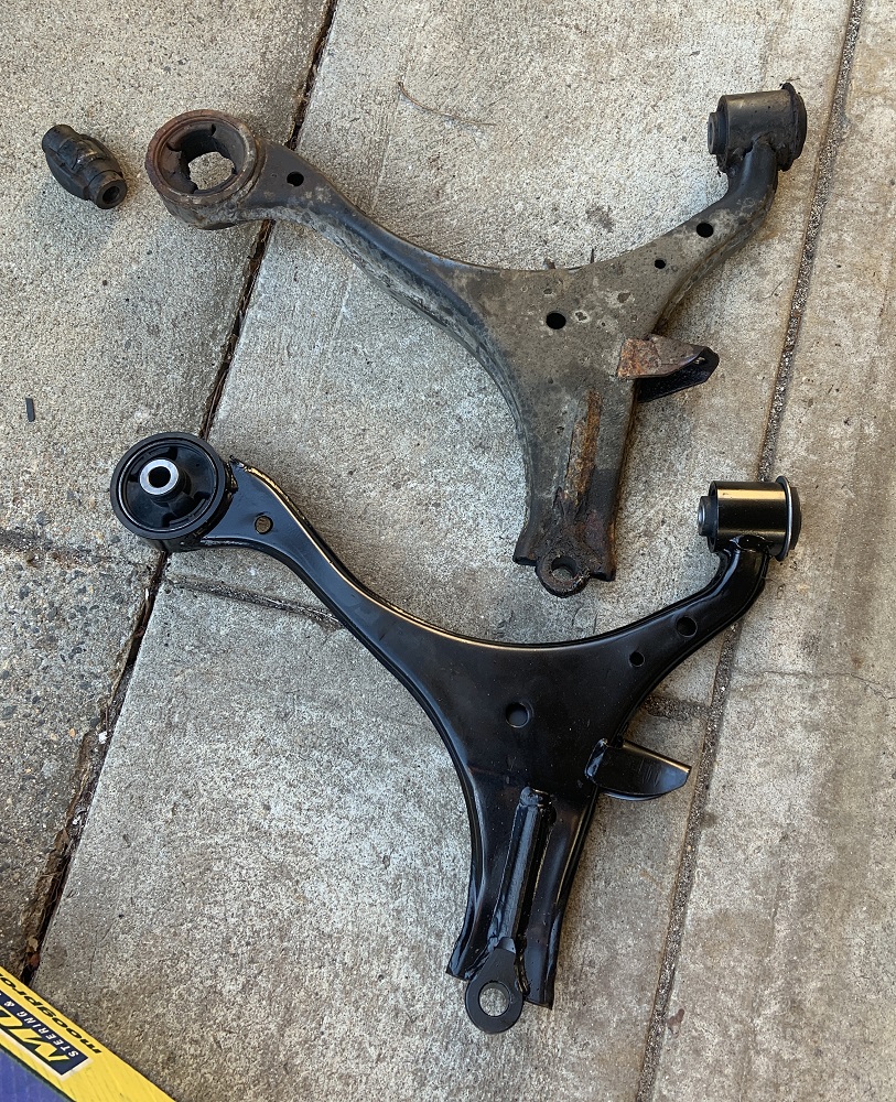
I don’t have much to update for the Fiero, I am still waiting for the engine to come back from the shop, but I may move the Fiero to the garage soon. My youngest brother has been doing work to the middle brothers 02 Civic, and that is taking up space in the driveway right now as it is on jackstands. He has a sweet Eastwood tool for flaring lines and is making all new brake lines for the car. It has burst at least 3 since we have had it, other than that it is a sweet car, stick, vtec, 45mpgs, 85,000 miles. I have been helping him with that, we are replacing the front end control arms, bushings, ball joints, inner and outer tie rod ends, and endlinks. The car is getting driven by my brother’s friend out to cali soon where my brother lives. Once the Civic is done the Fiero will get moved.
Some of my brother’s handiwork
I bought dew wipes for the Fiero from member silver 85 se and they look great, came in quickly too.
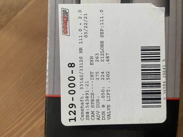
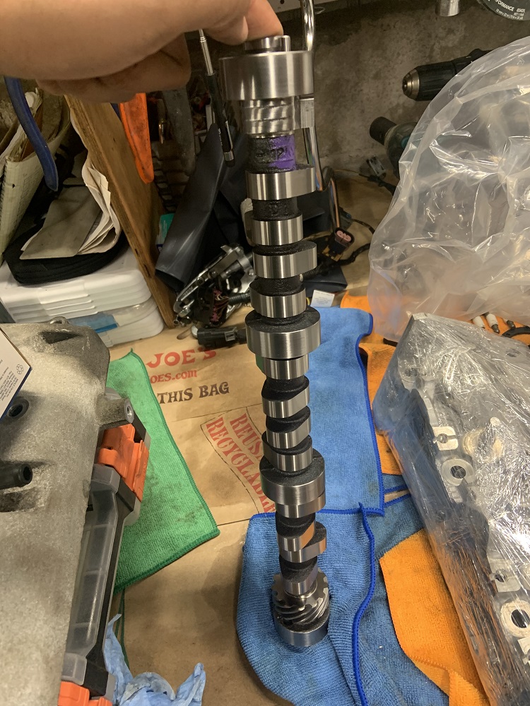
My cam came in too, and I was wrong, it does have a larger intake duration and lift than the exhaust.
I have also decided to get new roller lifters, I would be so mad if a roller broke and ate my cam and possibly trashed the rest of the motor. I can use my current lifters to size the pushrods for length and order the new lifters at the same time I order pushrods.
I have a big bin full of degreaser I have been letting the parts soak in, only the lower intake manifold is left to clean. I am planning to use Eastwoods engine enamel, it is 2 part and I always find 2 part paints are superior when it comes to longevity. I will probably go for the aluminum or cast iron colors, which are different shades of gray. I like gray because you quickly know if something starts leaking. I will take my oil pump apart soon too for inspection.
And in bus news, I have spent a decent bit of time stripping a camper that I knew someone was getting rid of, got a rooftop AC unit and a sweet propane setup including mini stove/oven, and collected all the hinges and latches and other bits that are mobile home specific. There was a really nice Dometic propane powered fridge freezer tower combo, but it was massive and will take up too much space unfortunately.
Edit to say that all my images are sideways from uploading on my phone, I will fix this later
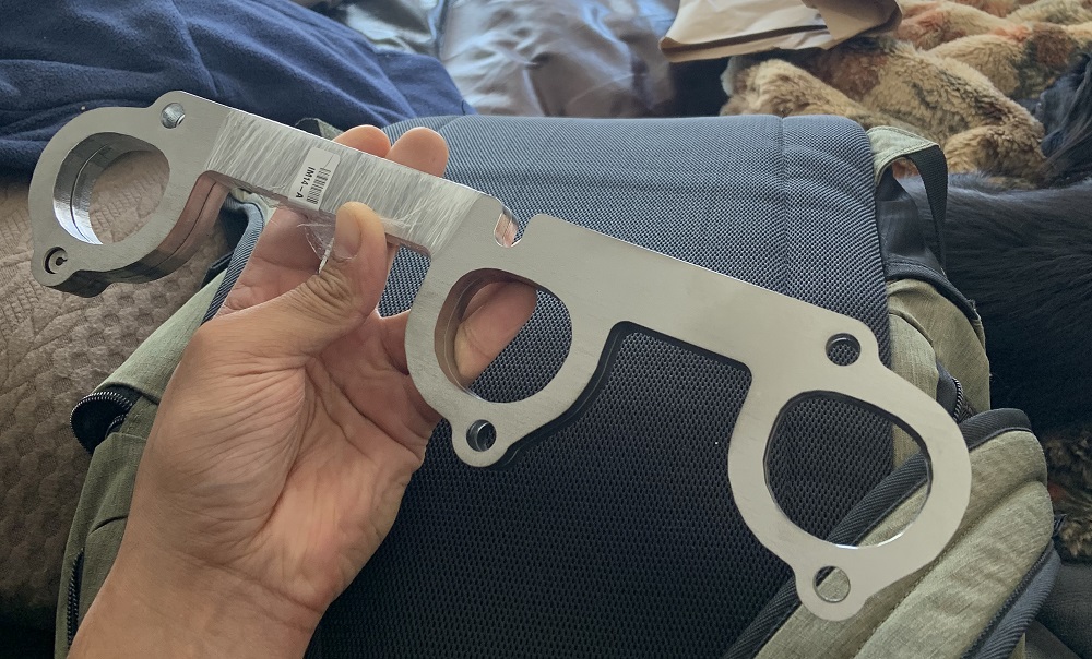
Edit also to say that ericjon262 was nice enough to send me his dxf files for the LZ9 headers he has been working on, and suggest OSHCut to me for where to get them plasma cut. I got 3/8” 304 stainless and it came out to around $150 for the pair which was awesome, I was expecting more for 304!
[This message has been edited by zkhennings (edited 04-10-2021).]
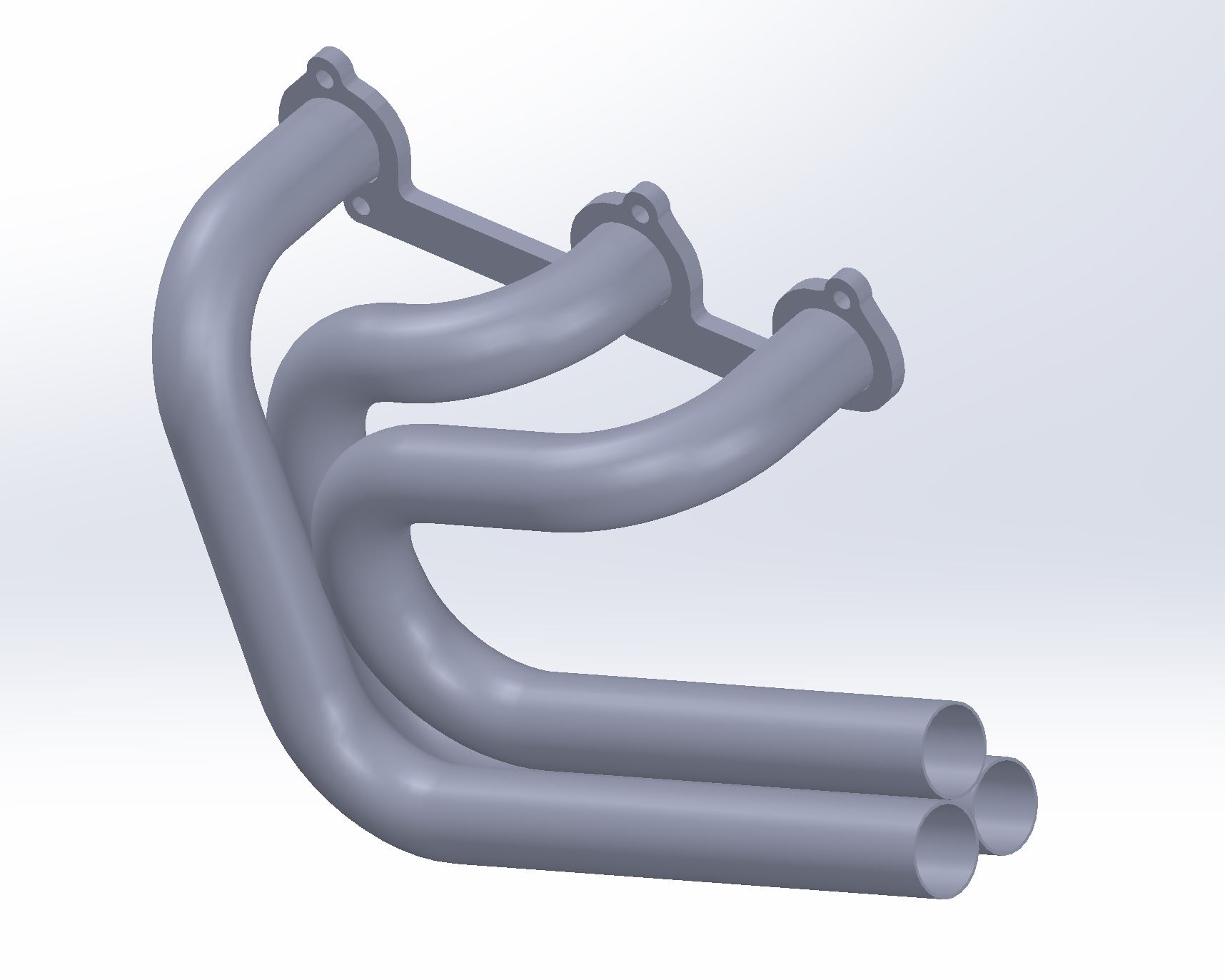
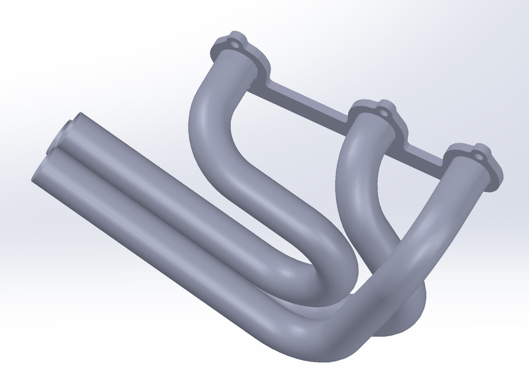
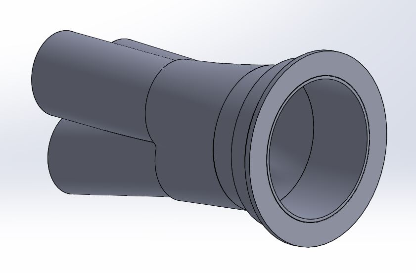
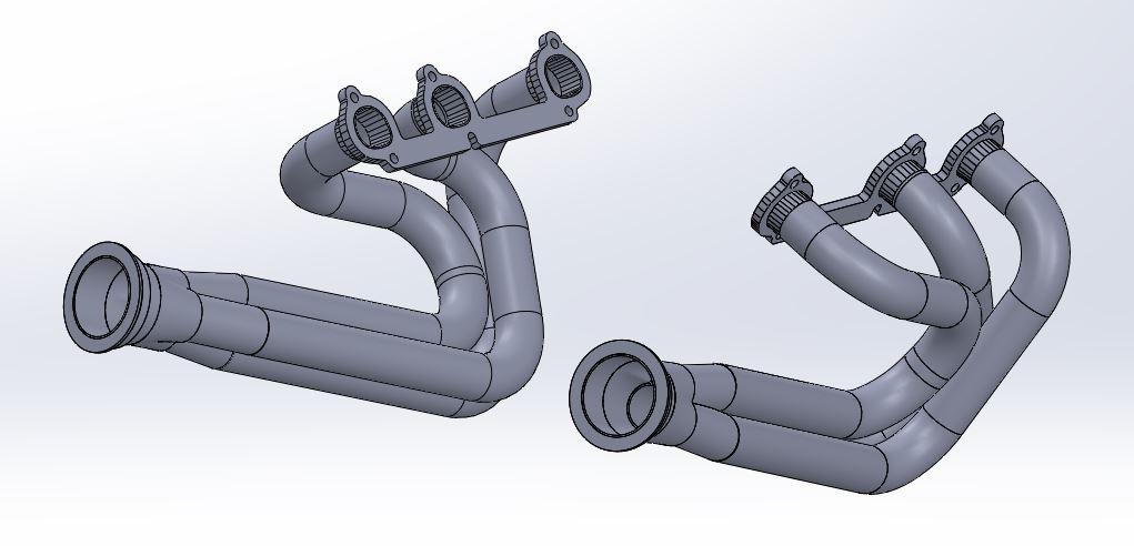
Using Eric's dxf I was able to mock up a rough set of headers. I imagine that I will need to make adjustments to the design if there are any components I need to clear. I know I will have to clear the back of the timing cover and the shift cables and throttle body on the firewall side headers, and the diff housing on the trunk side. These are 1.75" primaries and they are all within 0.2" of 28" long. I tried getting the headers to the same length as early on as possible while also minimizing sharp bends, leaving me flexibility to route the 3 straight tubes in different ways if I need to. It will be extremely easy to cut all the tubing to the exact shape and size necessary to make these as the majority of bends are 90*, and they are all the 2.63" bend radius of the tubing I have selected. I started by defining the tube that has the longest distance to travel. Both collectors will end up in the same place relative to the header flange. I think this will work out ideally for me but I need to do some mock up with the actual engine once I get it back. However this rough mock up gives me a good idea of exactly how much tubing to purchase and the quantity of bends I will need.
Firewall side headers
Trunk side headers
The headers should stay pretty tucked against the engine, I think they stick out max 6.375" from the head itself. I will have to check the engine bay for clearance once I get the engine mounted.
I intend to have an equal length Y pipe that runs over the transmission similarly to how my custom Y pipe was routed on my 2.8, I think I am just going to have it be 3" tubing like the rest of the exhaust.
If you think I will run into issues, let me know, I would like to get these more finalized so I can order material.
[This message has been edited by zkhennings (edited 04-11-2021).]
That's awesome looking! are you planning on having them mandrel bent so that all you have to do is weld them up?
------------------ "I am not what you so glibly call to be a civilized man. I have broken with society for reasons which I alone am able to appreciate. I am therefore not subject to it's stupid laws, and I ask you to never allude to them in my presence again."
I intend to order a bunch of 1.75" U bends and 1.75" 4' long straight sections. 4 feet long to avoid additional shipping charges. I should need 8 U-bends total, but will probably order a couple more for unexpected bends.
I have a 3D sketch defining each primary, and it is a simple matter of seeing how long each section needs to be and cutting it. I can masking tape the headers together to get all the angles right. then tack it in place, and weld each primary tube fully individually. Then I will tack them to the header flanges and the collectors and weld everything fully.
I wish 1.75" carboard tube donuts with a 2.63" radius were a thing so I could mock this whole thing up with C.A.D. to check all my clearances. Maybe I can bend some wire to shape instead and slide a 1.75" wood disk with a hole in the center along it to see if I will have clearance issues.
Originally posted by zkhennings: I wish 1.75" carboard tube donuts with a 2.63" radius were a thing so I could mock this whole thing up with C.A.D. to check all my clearances. Maybe I can bend some wire to shape instead and slide a 1.75" wood disk with a hole in the center along it to see if I will have clearance issues.
Something like 3/16" steel rod is easy enough to bend (and cheap), yet rigid enough to hold its shape. Can be tacked together for checking clearances.
Unless you also draw the engine bay in CAD, you'll have to do a mixed reality/computer-based approach.
I read years ago to use flex tubing to make mock up headers. It's not that expensive. ttps://www.ebay.com/itm/1-75-1-3-4-ID-x-18-Length-Galvanized-Flexible-Exhaust-Tubing-Pipe-1-5-Feet/164214857531
I just went and measured my car, from the portion of the head closest to the firewall, to the firewall is about 7.75", and from the portion of the head closest to the trunk wall, to the trunk wall, is about 5", the firewall gets further away as you go lower, the trunk is relatively flat. in both cases the top of the head is closer, and the bottom further, but only by a small margin. My car is also probably not the best car to measure, as all of the mounts are custom, and it has an 88 cradle swap.
------------------ "I am not what you so glibly call to be a civilized man. I have broken with society for reasons which I alone am able to appreciate. I am therefore not subject to it's stupid laws, and I ask you to never allude to them in my presence again."
Something like 3/16" steel rod is easy enough to bend (and cheap), yet rigid enough to hold its shape. Can be tacked together for checking clearances.
Unless you also draw the engine bay in CAD, you'll have to do a mixed reality/computer-based approach.
quote
Originally posted by jdv:
I read years ago to use flex tubing to make mock up headers. It's not that expensive. ttps://www.ebay.com/itm/1-75-1-3-4-ID-x-18-Length-Galvanized-Flexible-Exhaust-Tubing-Pipe-1-5-Feet/164214857531
quote
Originally posted by ericjon262:
I just went and measured my car, from the portion of the head closest to the firewall, to the firewall is about 7.75", and from the portion of the head closest to the trunk wall, to the trunk wall, is about 5", the firewall gets further away as you go lower, the trunk is relatively flat. in both cases the top of the head is closer, and the bottom further, but only by a small margin. My car is also probably not the best car to measure, as all of the mounts are custom, and it has an 88 cradle swap.
Thanks for the input guys, some 3/16" steel rod would be great to nail the path down perfectly, it would be very easy to make sure all the angles I have bent are correct.
The flex tubing looks like it could be promising too, I am not sure if I could do as accurate of a job getting all the bends precisely where they would be, but it has the advantage of being the correct diameter tubing.
And thanks for the measurements! Using the measurements and making a mild assumption that the closest point to the trunk wall on the head would be around 0.75" above the upper exhaust manifold bolt holes, I put a plane at 30* to the header flange to account for bank angle and set it to 5" away from that closest point I defined.
It looks like I should have acceptable clearance to the trunk wall with my current layout. I have the distance the headers take their first bend laid out so that there is 1" of tube starting at the head available to blend the D shaped port into the 1.75" circular profile of the tubing. Then it is just a matter of starting the primary that is closest to the flange (the middle primary on both of my designs) immediately after that 1" of blend. I could always route the tubes in more complex paths to get around this constraint, but I would prefer not to in order to minimize bends and minimize the amount of welds required.
quote
Originally posted by La fiera:
That's a plus for you! In case you don't get to your power goals NA it'll work wonders with nitrous or turbocharging due to the reverse split pattern.
My thoughts as well, I am itching to get this back together!
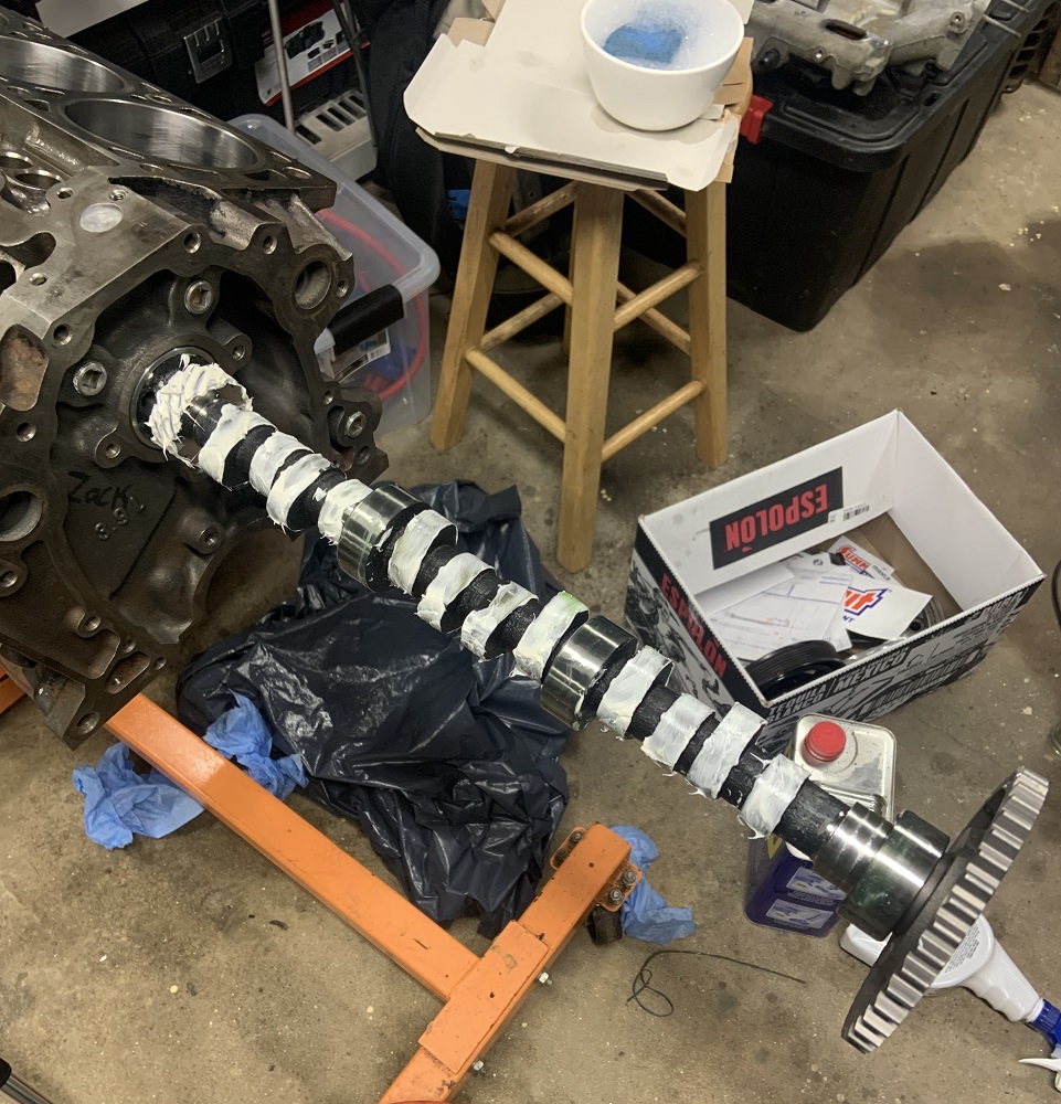
Machine shop is being slow as I guess 3 of their 5 guys are out because they are sick. I just hope they finish before the 22 as I will be getting my ACL surgery and will have a hard time putting the block into the backseat of the WRX/back on the engine stand once that happens. I already brought my C500 connector home to start rewiring/labelling it once I am stuck on the couch for a bit, I should bring my headlight motors home too to rebuild them at the same time. First order of business once I get the motor back is to install the cam and 2 valves with springs and get the pushrod lengths measured so I can order those and the lifters. Then I will paint the block and other parts, install the bottom end, and bring the small various components to cryo treatment facility.
Hopefully this week my brother and I finish our other brother's Civic, and then I will get the Fiero in the driveway and pull the cradle out to get ready to mock up the front engine mount.
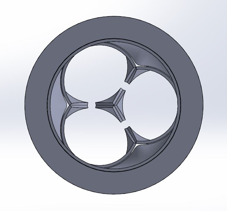
the flanges are drawn so that each "D" port has the same perimeter as a 1.75" tube, so fitup should be fairly straightforward. I can draw up a set of dies to press the tube into shape if you want.
------------------ "I am not what you so glibly call to be a civilized man. I have broken with society for reasons which I alone am able to appreciate. I am therefore not subject to it's stupid laws, and I ask you to never allude to them in my presence again."
Thanks Eric but with your DXF I will be able to get that made if I need it, I did see that the perimeter of the D shape was the same as the perimeter of the 1.75" tubing when I checked in SolidWorks.
I have been picking away at the various items needed to be done, I have had a vat of degreaser that I have been cleaning all the parts in and now they just need a hand clean up to get rid of oxidation.
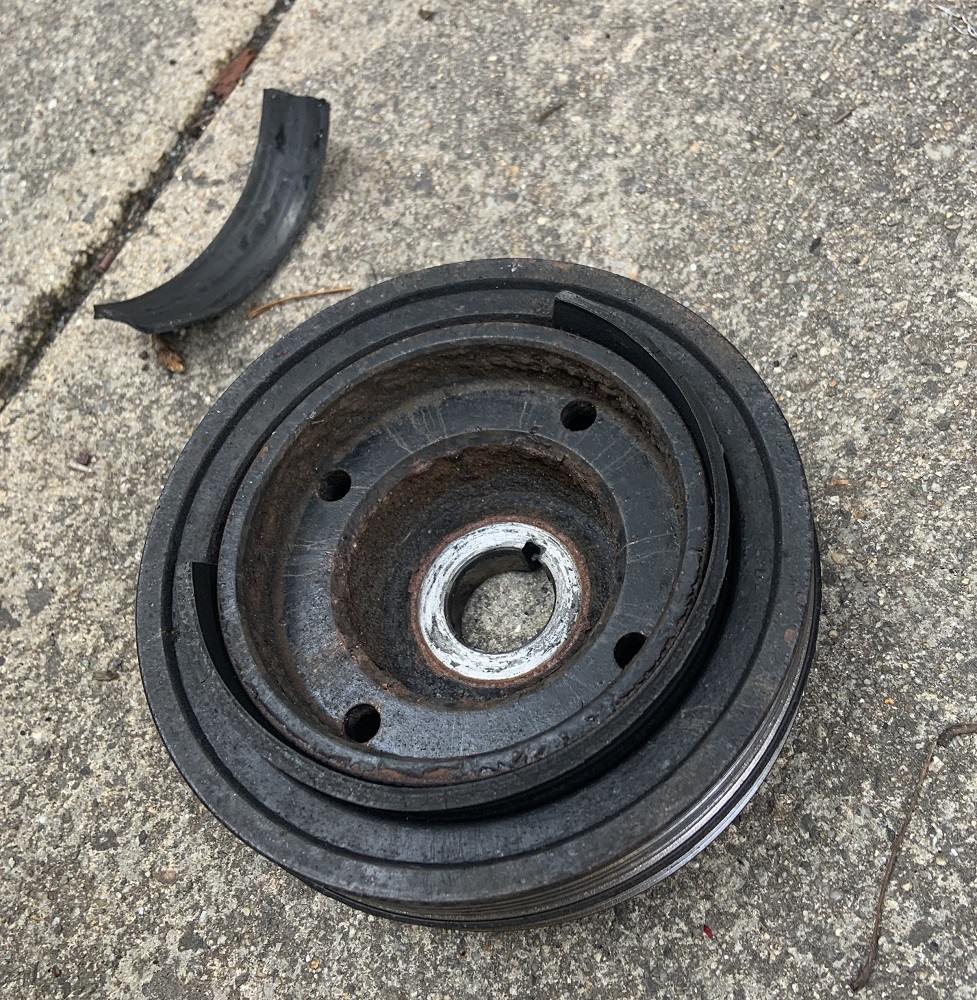
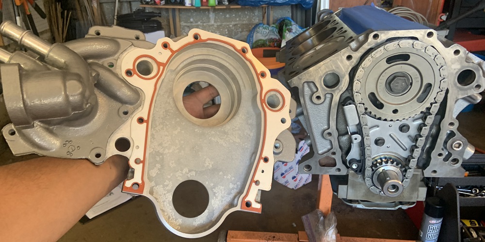
My WRX's harmonic balancer came apart and came close to messing things up under the hood, I caught it before it destroyed the timing cover.
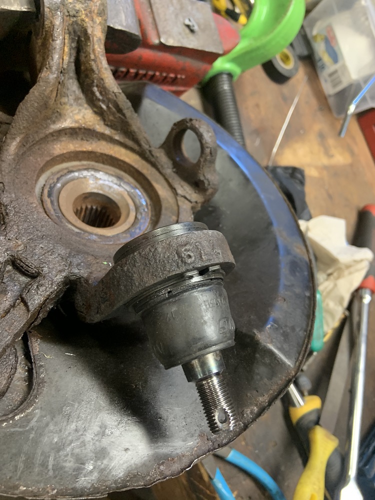
I helped my brother rebuild our other brother's 02 Civic, it came out good, in addition to new brake lines that he made, we installed new control arms and bushings, ball joints, tie rod ends, and endlinks. The car drives awesome now. As you can see from the pic, the front bushings on both sides had completely separated and it was driving like garbage.
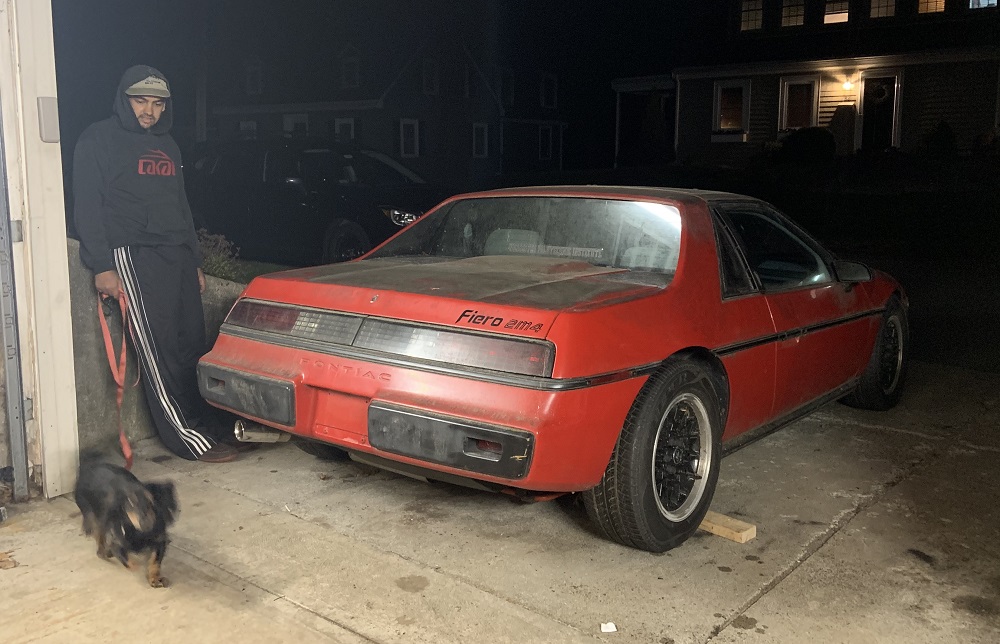
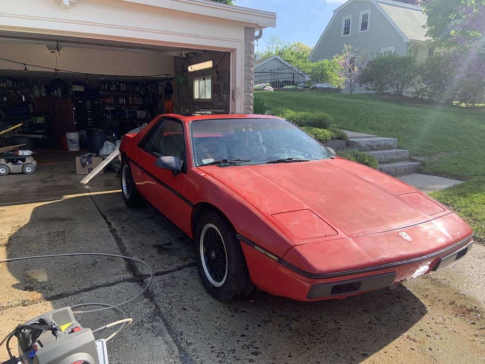
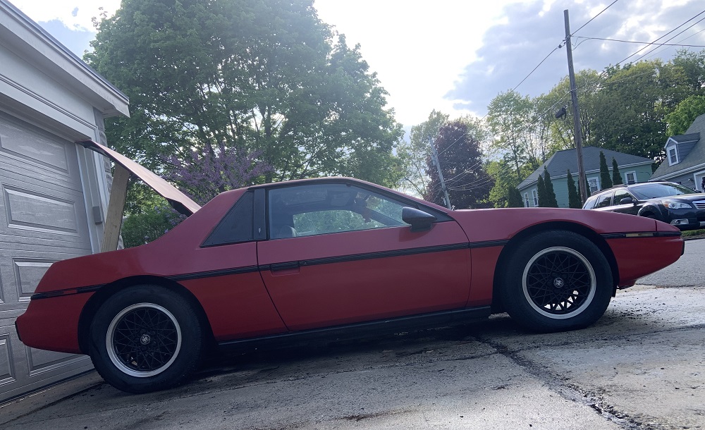
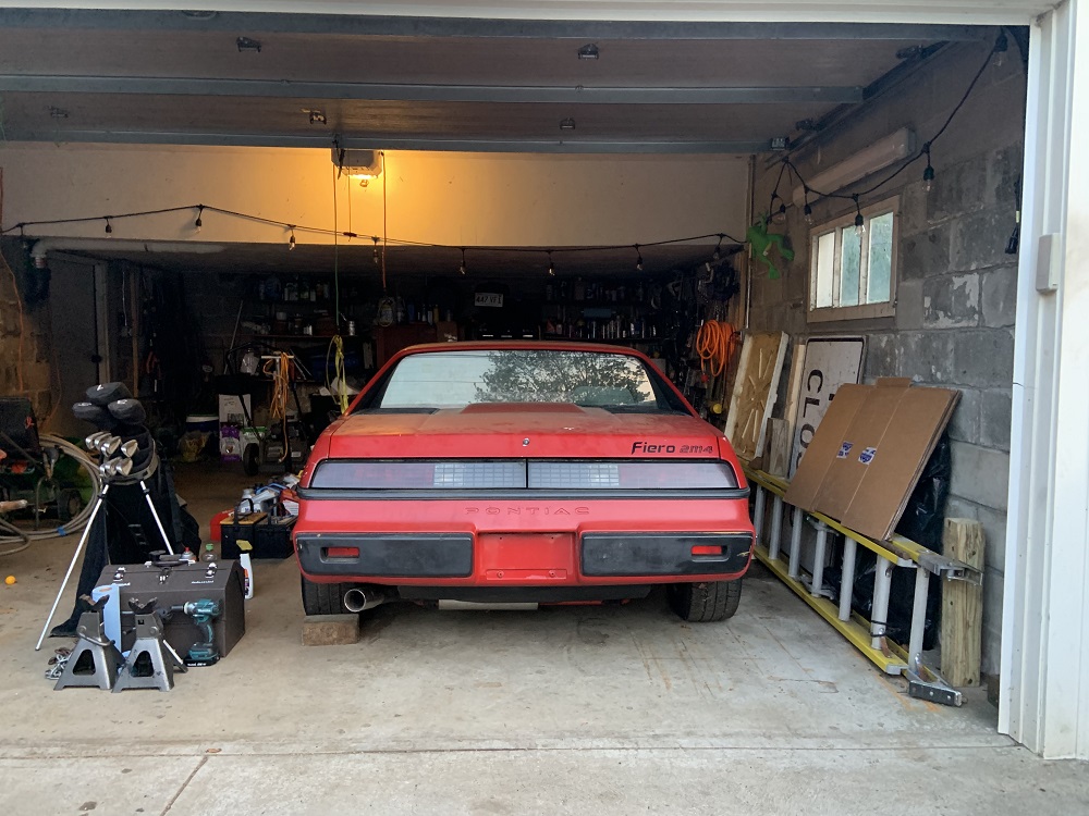
And the result of all this Honda work was that I could move the Fiero into the driveway in front of the garage where it sits ready to be worked on. It had not been moved in 6 years so it was pretty nostalgic to see it in the driveway again.
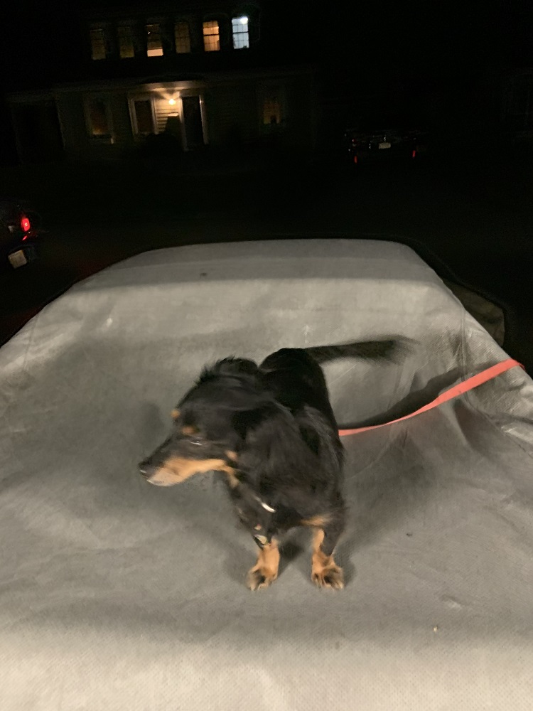
My girlfriend's dog Limo loves cars and bikes and motors, he loves leaning into the turns in the car, and he goes in a backpack when my girlfriend rides her GSXR 600 and he loves it. He comes to the motocross track too and watches all the riders go by. I introduced him to the Fiero and he explored inside and then I put him on top of it to chill.
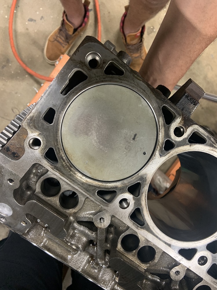
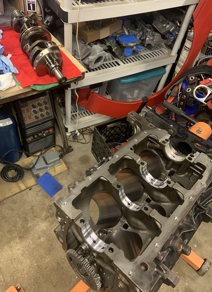
I also managed to pick up the engine block and heads from the machine shop a day before my surgery. I got the block back on the stand and ready to go. They cut the valves, the valve seats, skimmed the heads, honed the cylinders, put in the cam bearings, and I brought the cam with me and we checked the fit and it is perfect. They said the bores were very round and straight and only needed a light honing. They still have my rotating assembly for balancing but I am not worried about picking that stuff up, and it is not affecting me measuring my pushrod lengths to get those on order.
I had my surgery the next day on April 22, and the following day my header flanges came in from OSHcut, 3/8" thick 304 SS. They came out great and need minimal clean up. They are slightly bent but the welding will make them warp anyways.
Hopefully I will be off crutches soon and able to continue my progress, there are plenty of little tasks on the car to do.
oooh shiny! let me know how they fit up, and if I need to make any adjustments to the design!
------------------ "I am not what you so glibly call to be a civilized man. I have broken with society for reasons which I alone am able to appreciate. I am therefore not subject to it's stupid laws, and I ask you to never allude to them in my presence again."
I picked up the remaining parts from the machine shop last weekend, the crank has been balanced and polished, and it turns out the rods when torqued to 40ftlbs with the ARP rod bolts were still within factory clearances, so I did not need the .002" over OD rod bearings.
I got sick of waiting to not be on crutches anymore to do more work, so I got ahead of some longer lead items.
I needed to confirm that the PAC -0.050" valve locks were going to give me an install height that was 1.800" or a little less, and I need to still measure my pushrods so I can order a custom set along with new lifters.
First I cleaned the block with some unscented dish soap and water and blew it free of any minor debris from the hot tanking process. I then coated the motor internal surfaces in WD40.
Time to install the cam. I wiped it clean and then coated the journals in assembly lube, and the lobes with a Comp Cams valvetrain assembly paste. I thought I would be able to use the paste on the whole motor, but doing a little research it seems it is just for valvetrain. I installed the thrust plate as well.
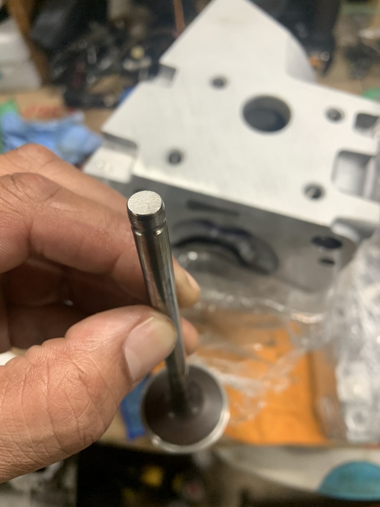
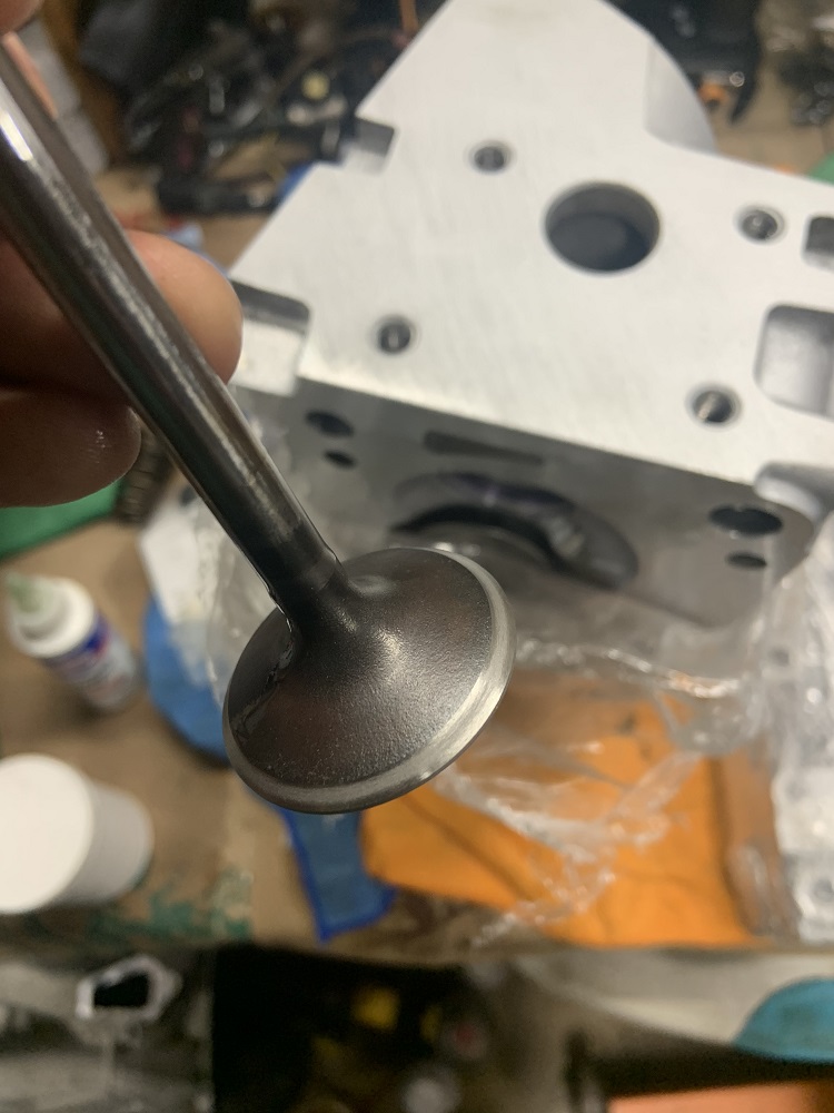
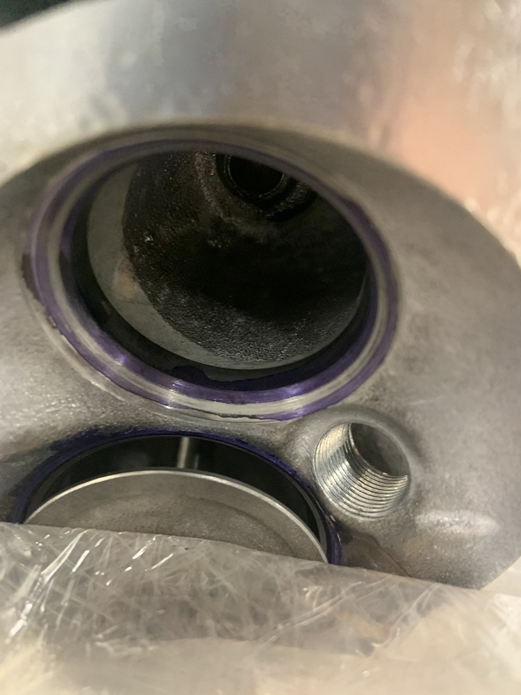
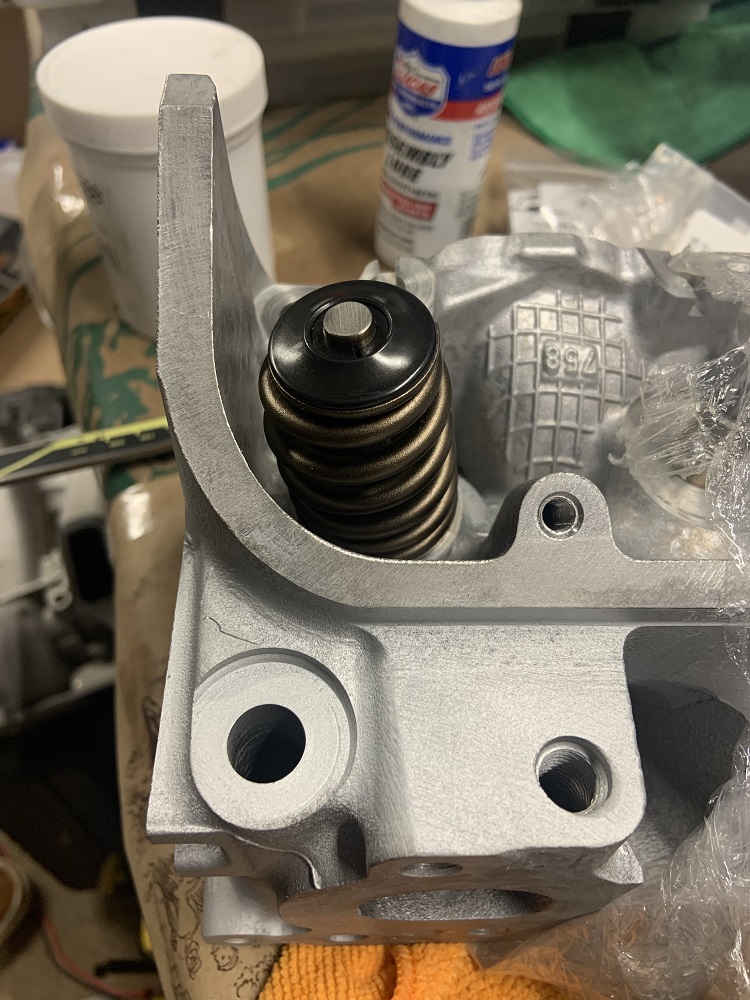
My old lifters were at my apartment so I was unable to go further with measuring the pushrod lengths, so I assembled one of the valves with the PAC springs, locks, and retainers. The valve tips and face have been ground, the valve seats were given a valve job, and the valves were lapped to their seats.
The install height came out perfect, when measuring from the top of the seat to the underside of the retainer it came out to 1.800" exactly. Therefore it is a little less than 1.800" as the calipers have to be slightly angled to make the measurement since it is a beehive spring. If I retained the stock spring seat retainer thing (which did fit, but were unnecessary with these stronger stiffer springs) then the install height would have been closer to 1.750" which is what the locks advertise. But I will be fine without the additional seat and open pressure as the valvetrain on the 3900 is lighter than on the LS that these springs are intended for. I went ahead and ordered the remaining locks and retainers from Summit along with an Optima Red Top battery. The retainers are in stock but the locks have some lead time so I wanted them ordered ASAP.
Next steps include installing a stock valve spring, retainer, and lock on the second valve for the cylinder, installing two of my old lifters, installing an old head gasket with some painters tape on the head and block surfaces, and measuring the pushrod lengths. I will also install the crank and Plastigauge it to confirm that none of the clearances are too tight or loose, and I will probably Plastigauge the rod ends too just to verify the machine shop's readings.
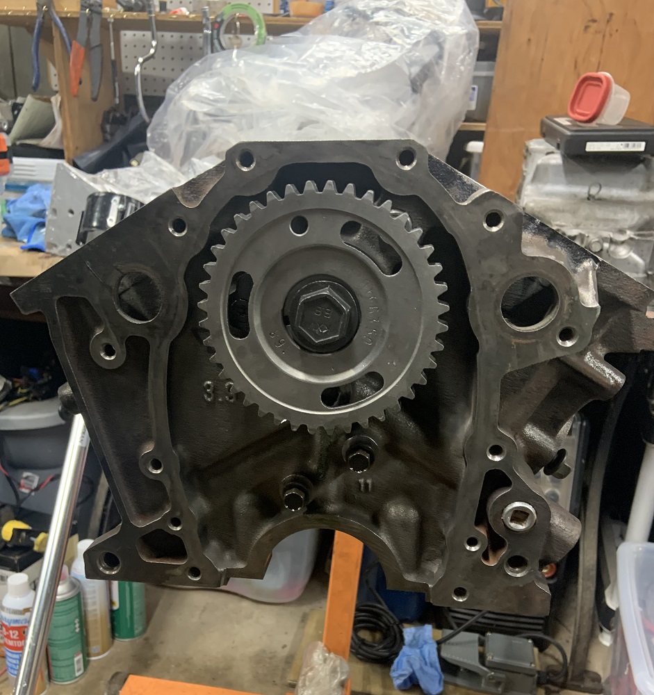
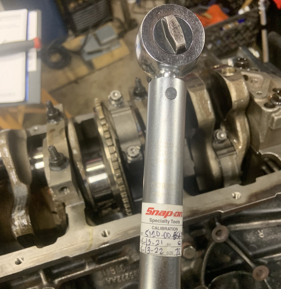
I need to send out my torque wrenches for calibration as well and get a degree wheel (bought). I may only need to send out my 0-75ftlbs torque wrench as the highest torques are in the 50ftlbs range. They are all finished with an angular displacement. The 3400 camshaft sprocket bolt needs 103ftlbs of torque, but I am not too worried about my larger torque wrench being far enough off to cause any issues.
And here is a pic of the LS piston in the 3900, once the crank is installed I can 3D print a thin bearing to make it bolt up and I can measure where everything ends up with a stock LS1 rod. There is confusion as to the lengths of the 3900 rods, the manual says 5.9", but others have measured otherwise. This will give me an additional data point.
I ordered a tapered 99mm ring compressor as well as I realized while writing this post that I had not procured one yet. It is unfortunate because my brother has the same one in 99.5mm size, and we tried it and it was, well, half a millimeter too big.
[This message has been edited by zkhennings (edited 05-06-2021).]
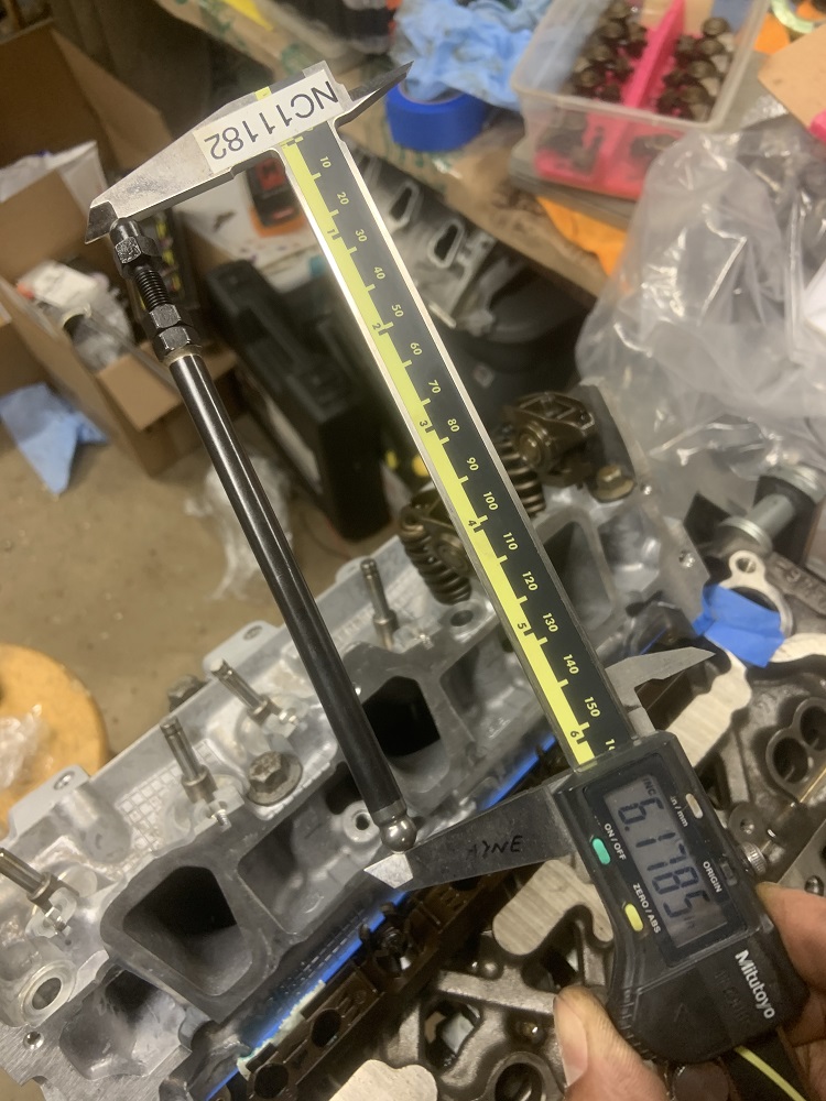
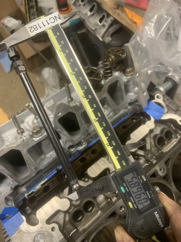
Getting everything prepped for measuring the pushrod lengths.
Measured the pushrod lengths.
The LA's Finest Degreaser makes parts super clean, but I was having issues with it oxidizing after. This stuff is phosphoric acid and I read it is good at dissolving oxidation.
It did a good job, I think it should be paint ready, but it looks a little dark. Might just be what it looks like when the acid etches the surface.
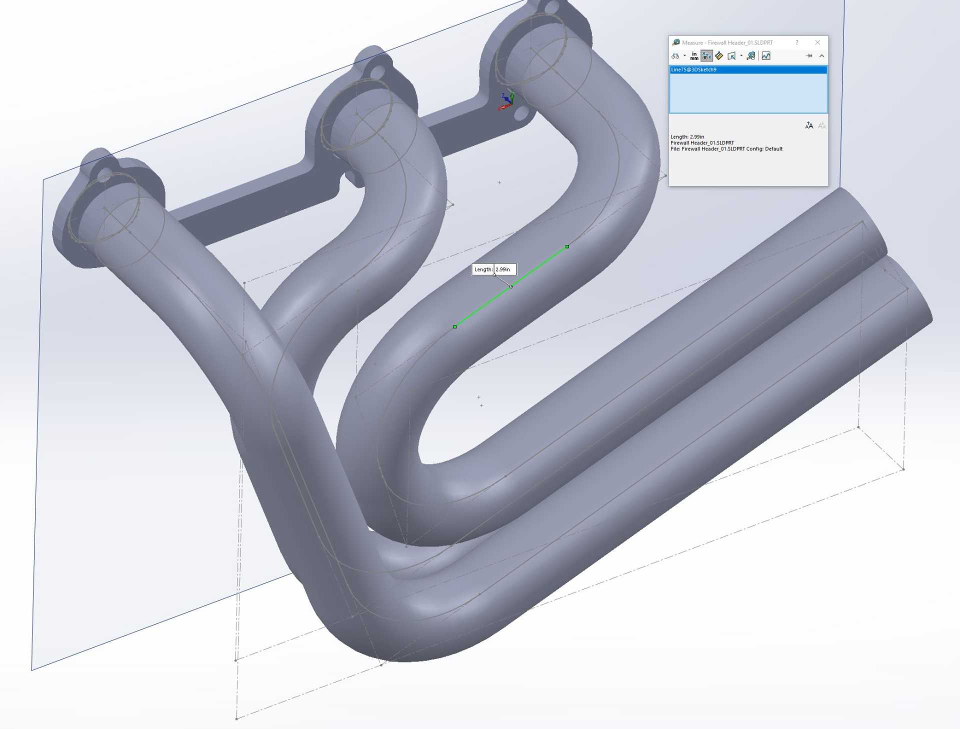
I did some more CAD on the headers too, I wanted to figure out what I was doing for header collectors.
Here it all is assembled. Looks like the headers are a little too long, I want to see what it will look like in the car.
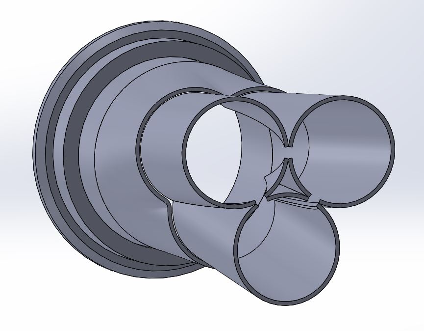
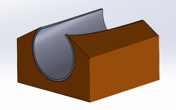
To cut the tubing to make the collector I made this 3D printed guide to guide the cuts to the tubing probably on a band saw.
Pushrods are on order, wrench was sent out to CDI for calibration, and I am waiting on a bunch of parts.
[This message has been edited by zkhennings (edited 05-08-2021).]
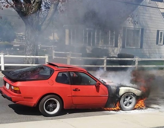
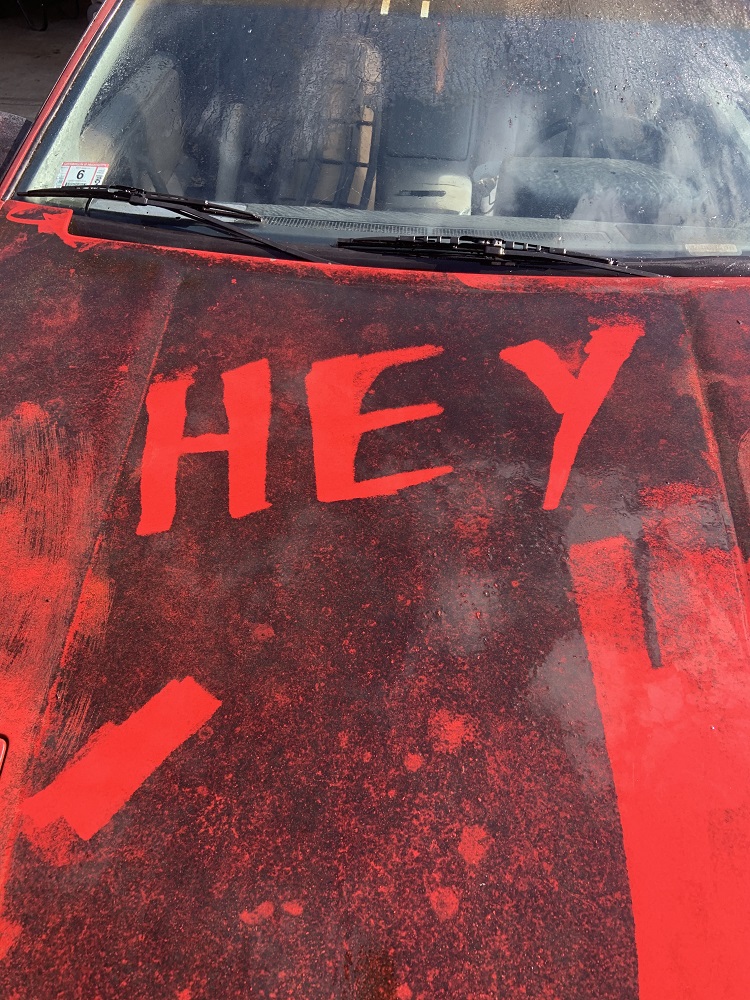
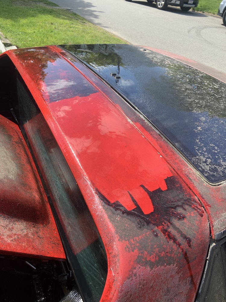
My friend had a pretty sweet 944, it was all rebuilt, long tube headers, rolling on Toyo Proxes. He smelled gas the other day and pulled over.
And suddenly I decided I was no longer going to keep my rubber fuel lines. No one needs to hear about more Fieros catching on fire.
I needed a fuel pressure regulator as the stock fuel rail only has a single line in and I needed to route a return. I bought this Aeromotive unit, it is adjustable 30-70 PSI, 1:1 rising rate if I ever want boost, comes with a liquid filled pressure gauge, and three -6an fittings. It is a very reliable and stable unit, and I do not want to take chances with the fuel system.
I bought this 3/8" aluminum fuel line that will run from the tank to the regulator, since the Aeromotive unit has the same size inlet, outlet and return lines, I figured it would be fine to run 3/8 line for the feed and the return line. I can always add in a restrictor to the feed line if the fuel pressure creeps.
I bought some nylon braided fuel hose as well as some right angle fittings to go from the regulator outlet to the fuel rail. The fuel rail will get a -6an male compression fitting. I want to flip the fuel rail so the inlet is on the front of the motor, that will keep the fuel system short and compact and away from the exhaust, but whether I do or not will depend on difficulties with securing the rail to the LIM.
I will put a bead into the aluminum line where it will be coupled with short rubber hose sections and hose clamps to the fuel sender outlets on the tank, and then the fuel feed line will have this compression fitting to mate it to this K&N fuel filter, the fuel filter can flow up to 18gpm so it should have no problem dealing with any possible future mods that require more fuel, it also has a SS mesh screen filter element so it can be pulled out and cleaned with nothing to replace. I know it is pricey for a fuel filter but it will never need to be replaced and is made in the U S of A. There is another compression fitting to aluminum line on the other end of the filter, and then a compression fitting to the regulator inlet.
On the return side of things I will have the same female compression fitting above or below the fuel filter, and then this male compression fitting to aluminum line to another female compression fitting to the regulator return outlet. This way if I need to drop the tank I can undo the aluminum lines at the fuel filter and drop the tank without long cumbersome lines attached.
Let me know what you think, in the past I have welded some AN fittings to stock stainless lines and run off the shelf built hoses, but this is my first time doing custom AN lines. Pretty positive my scheme will work well, but open to input.
[This message has been edited by zkhennings (edited 05-10-2021).]
I don’t think the nylon braided lines are nitrile, they seem like rubber line with an interal braid, and they have a nylon braid going on on the outside instead of stainless. I got them in today and checked them out.
My WRX's harmonic balancer came apart and came close to messing things up under the hood, I caught it before it destroyed the timing cover.
That happened to me at the track bach when I had the 2.8L V6. It was the second one I shreded, too much RPMs for the stock balancer. Since you are putting all this time and effort on this engine invest in one of these!
The ones for the SBC has the same snout size as the stock and it fits perfectly. I had to grind the timing cover a bit to clear it but let me tell you; If you asked me that if there is ONE part that I can say made a night and day difference, this is it! Engine revved smoother and I was able to rev it higher, no vibrations, nothing. Wish you the best mate!
on a 2.8, this is easy enough, on a later FWD engine, with the FWD timing cover, it gets a little harder, as the balancer is also the crank pulley. one for a gen II SBC may work, if they're even offered. measurements would need to be taken to make sure everything fits as required, and I would also contact someone at ATI prior to purchasing and asking about using it on a 60V6 prior to purchasing, as I'm sure there's a ton of engineering tied up in a balancer beyond basic fitment.
------------------ "I am not what you so glibly call to be a civilized man. I have broken with society for reasons which I alone am able to appreciate. I am therefore not subject to it's stupid laws, and I ask you to never allude to them in my presence again."
That is cool, I have been wondering if one of those dampeners would be available for these engines. I will have to look into it more and probably get in touch with the manufacturer.
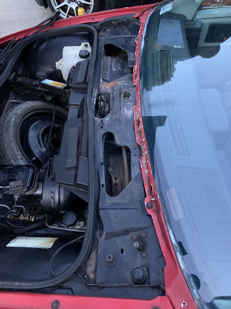
The Fiero was filthy even though it had a car cover, at some point the cover must have lost its protective coating. The pressure washer made an easy but time consuming job of blasting it clean.
The cowl was filthy, it was full of dirt and acorns and other crap, so I pulled it off, pressure washed everything clean, and removed all the old sealant material. I used a slide hammer to remove the windshield wipers and it only took one light hammer pull each.
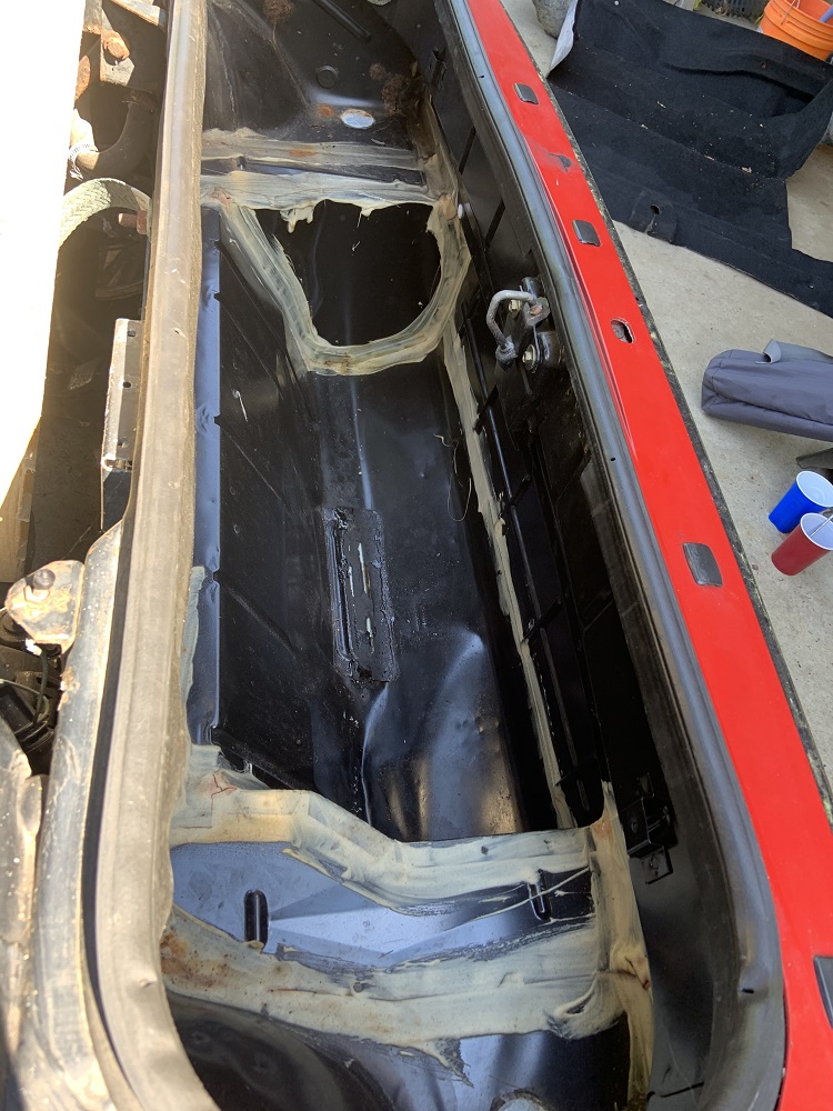
I pulled the trunk carpet out and soaped and pressure washed it. The trunk is in pretty good shape, it is very clean asides from 3 or 4 small rust spots I will repair. I have to pull the rear shell and make sure the frame rails are still in good shape.
I power washed the whole car, all in the engine bay and lifted the car up and washed underneath it too. I hate working on a filthy car.
Here is the car all cleaned up
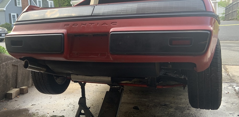
Also here is a pic of how my exhaust was routed and will be routed out the back. I will be using 3" stainless instead of the 2.5" mild tubing I made the 2.8 exhaust with.
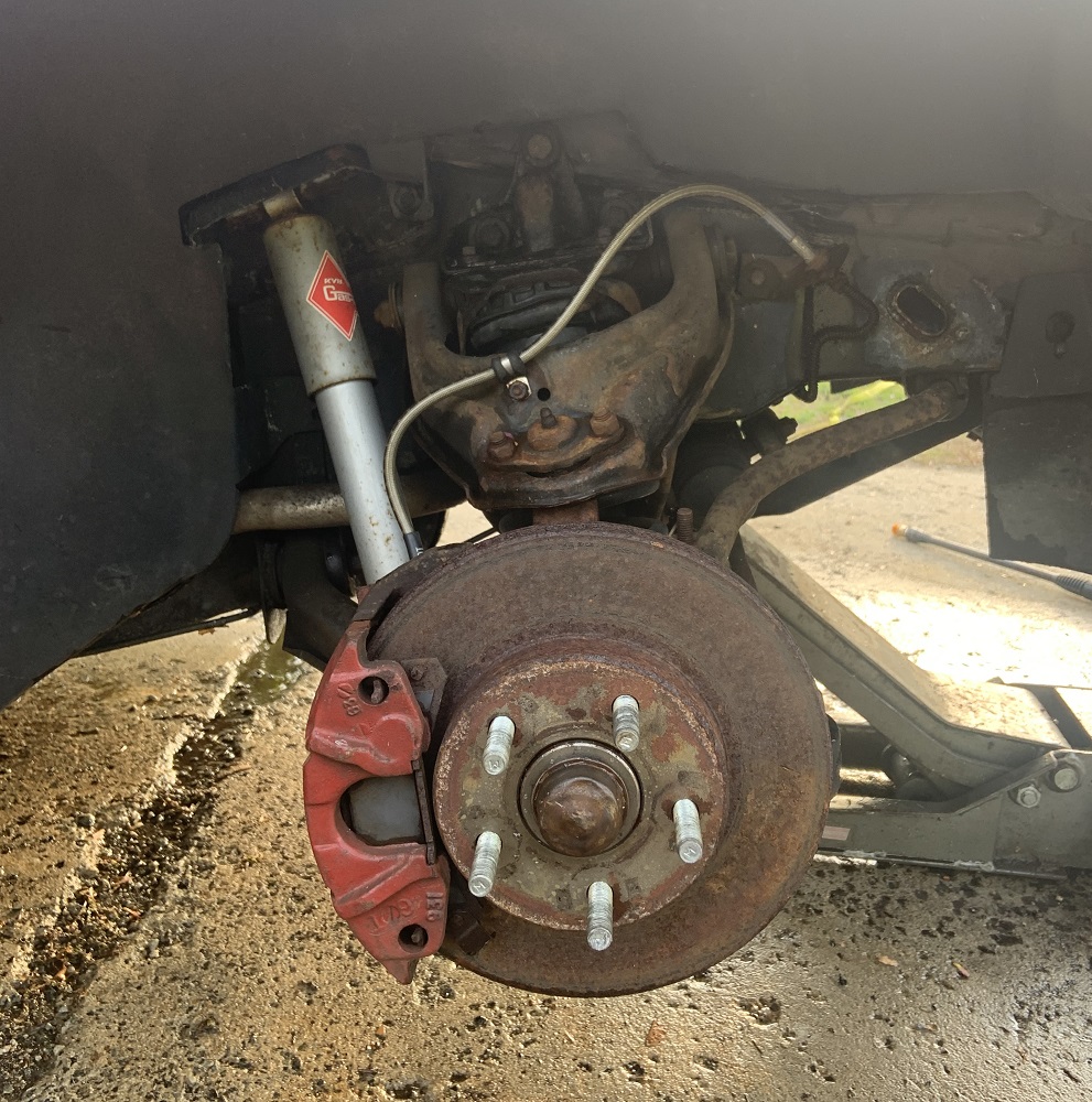
Here's the brake upgrades on the front, I may try and clean the rotors with electrolysis, but I may just get new ones. The pads have a ton of life and will be fine.
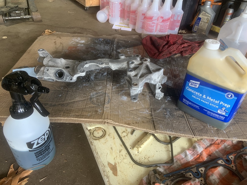
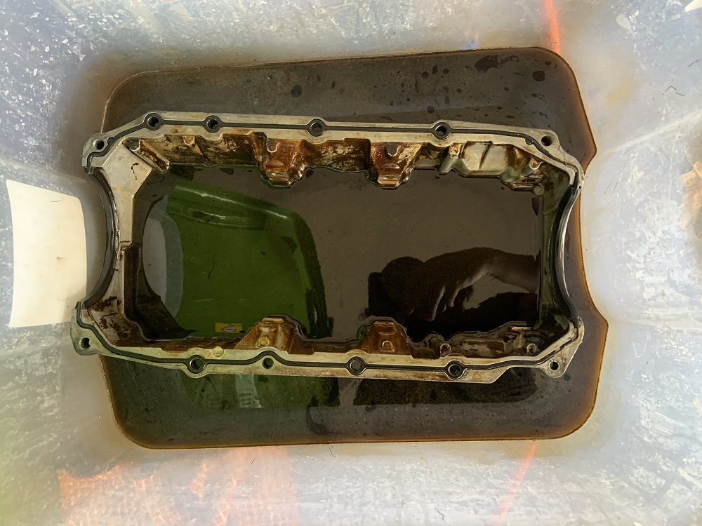
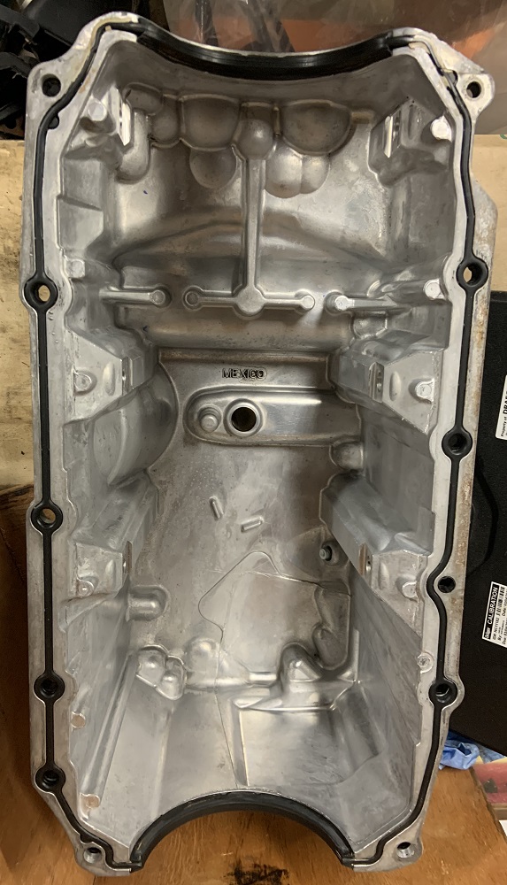
I spent time soaking parts in degreaser and then pressure washing them until they were clean. Here is the oil pan soaking.
And here it is clean
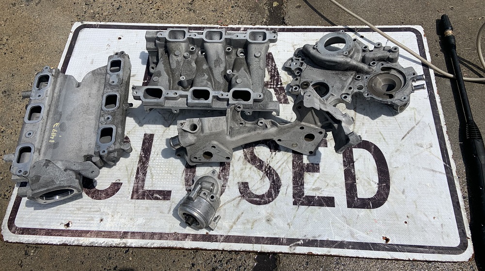
The LIM, crossover, and timing cover all got degreased and then had multiple treatments with the phosphoric acid etching spray. I would spray the parts with it and once it stopped foaming I would pressure wash them off. I went a little too hard with this and some of the parts got a little rougher than I wanted, I wouldn't recommend more than 3 or 4 goes with the phosphoric acid, I probably did around 10+ washing cycles.
Here the parts are mid way to clean
Here they are all foamy with the acid on them
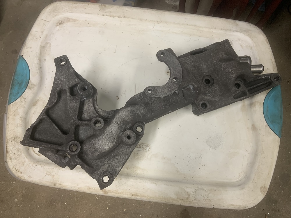
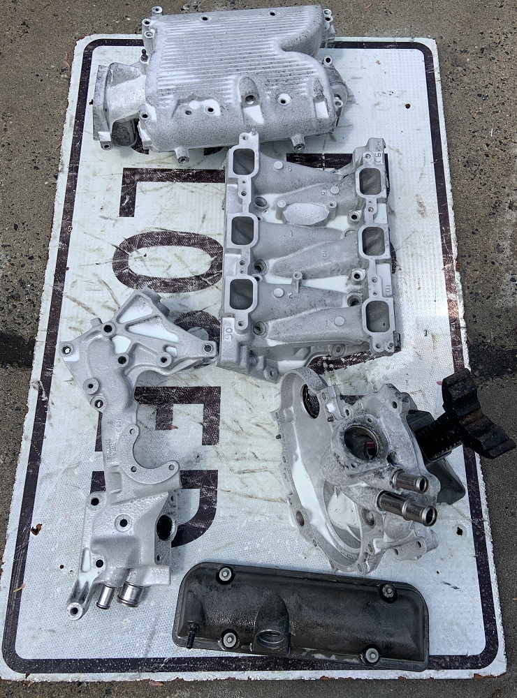
And here are some of the parts fully cleaned.
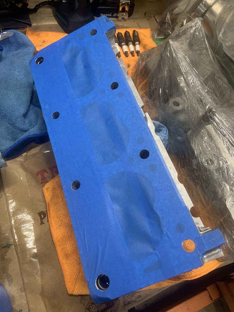
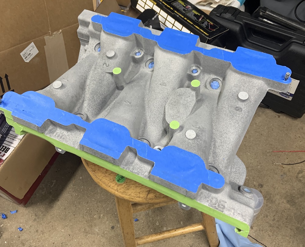
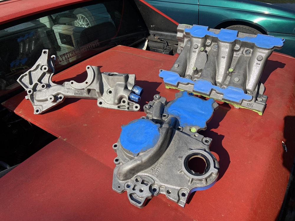
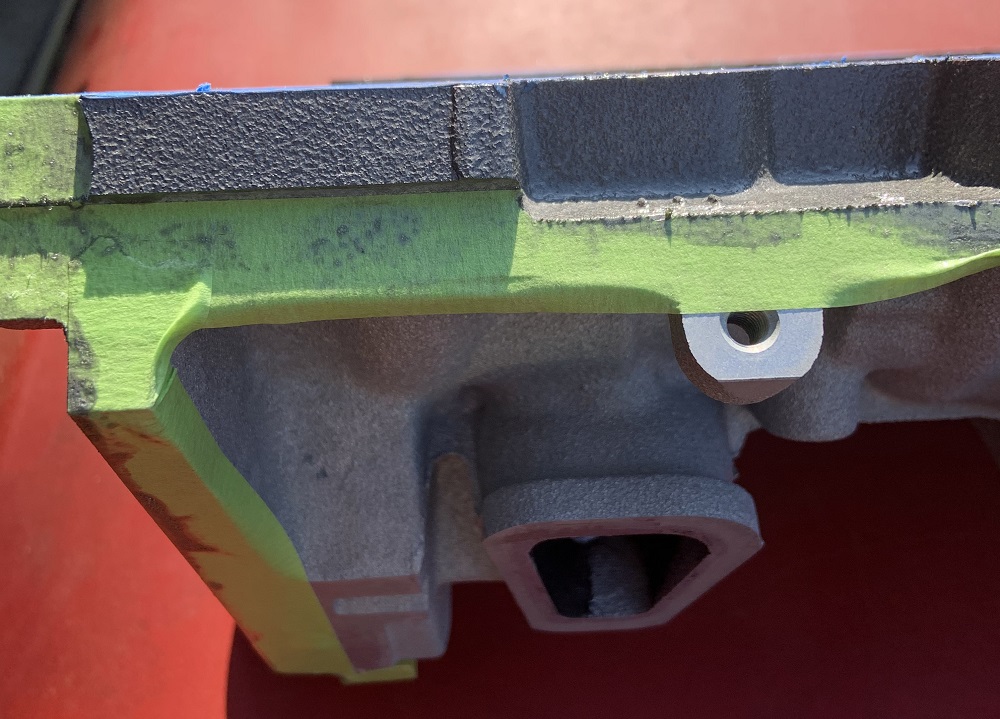
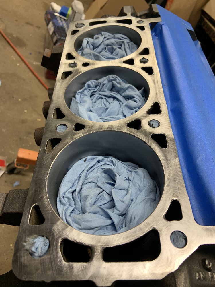
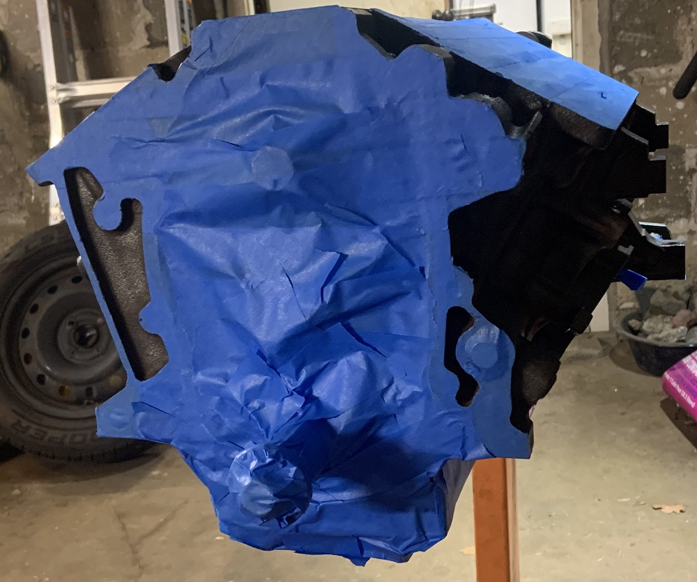
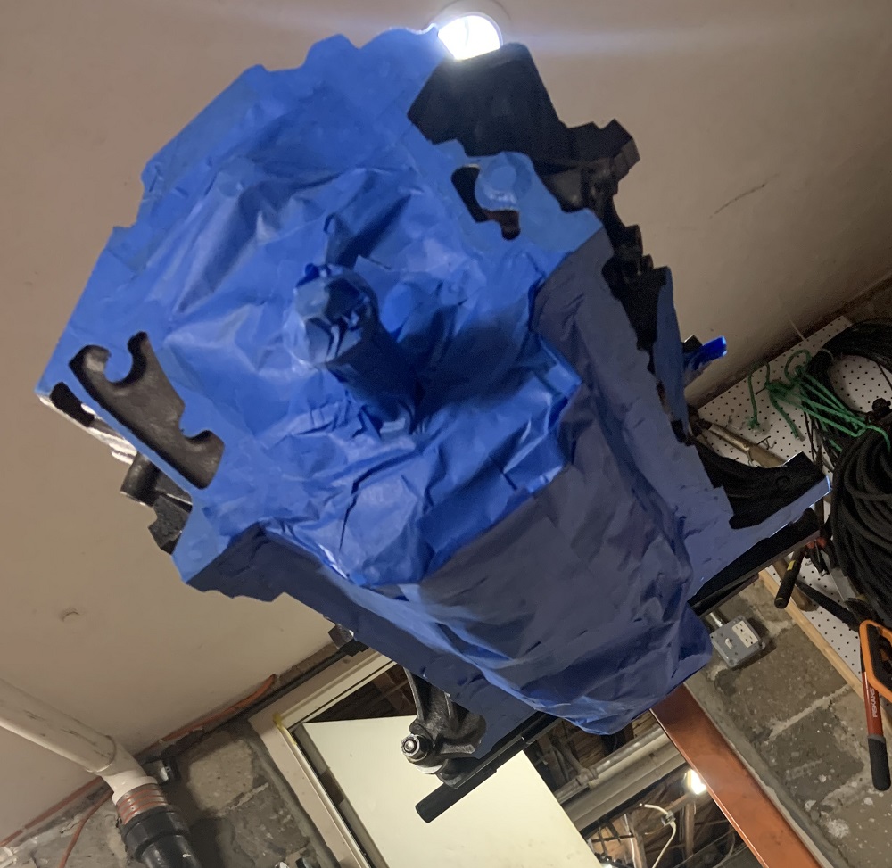
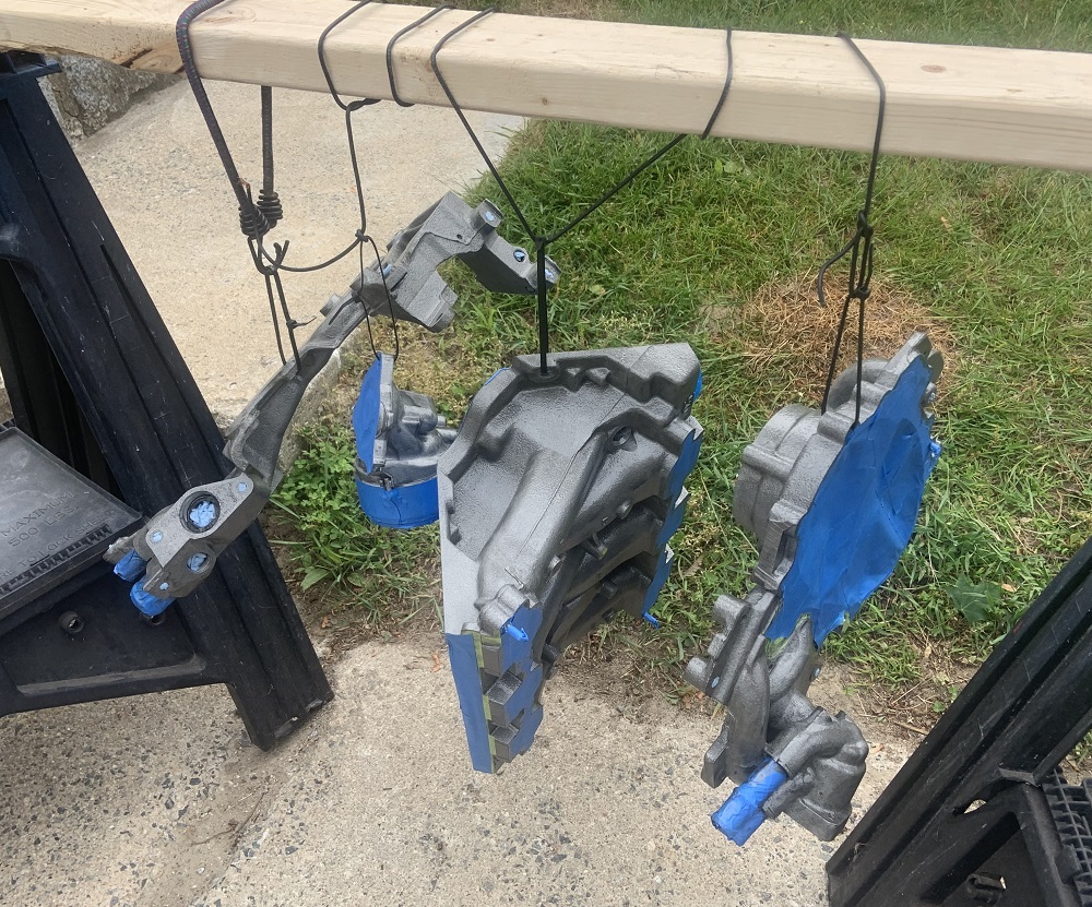
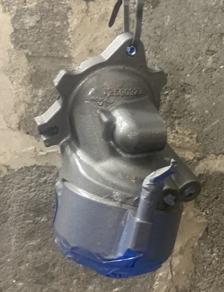
I taped up all the parts for paint.
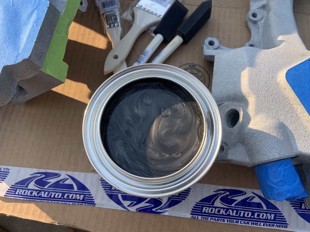
The paint is a 2 part Eastwoods ceramic engine enamel good to 650*, it can be used for brake calipers and things too. The engine builder recommended it over POR's engine enamel, which is what I was planning to use. The paint is a nice metallic dark gray, it will look good, be easy to clean, and seal up the porous aluminum. I will paint the block with it, I will not paint the oil pan, and I may paint the heads with it.
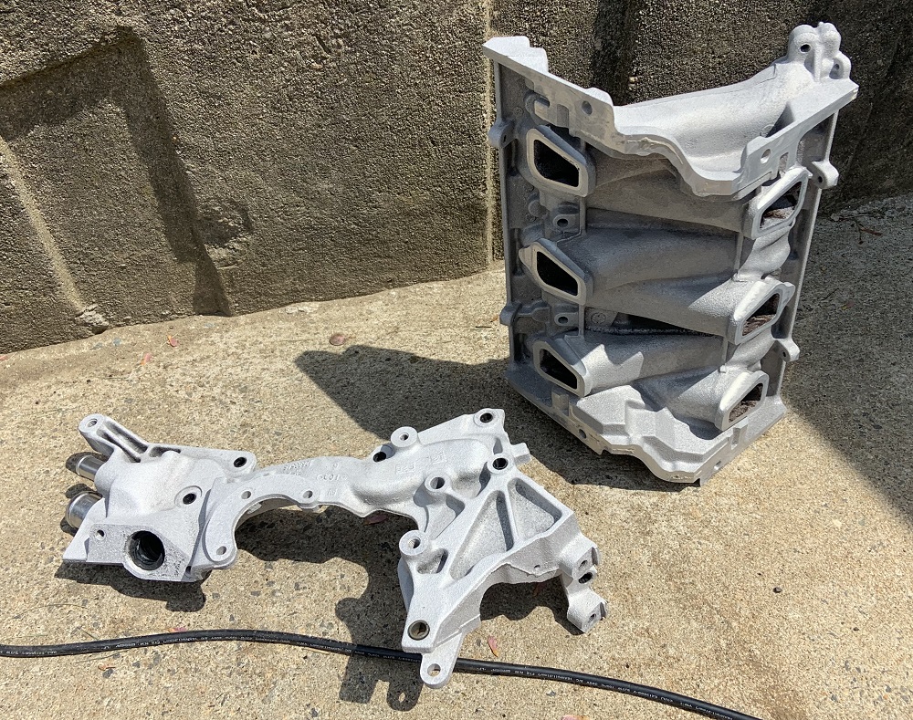
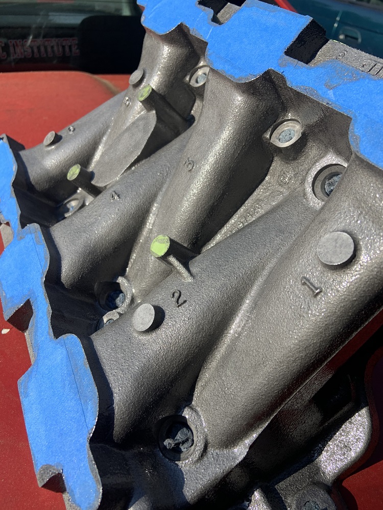
And here are the parts painted, I painted them with foam brushes so there is no brush strokes, I think I may end up spraying a final coat on them with the guns. They have 2 coats here, the first coat was very light in color compared to the second.
And here is a color comparison to the bare aluminum.
I have been working on this all week, I worked a 70+ hour week last week to hit some deadlines on making functional prototypes, so my boss told me to take most of the week off and I have used this time to get a lot done. The engine assembly starts today, I will be getting the crank in at a minimum after checking clearances. My torque wrench came back from CDI/SnapOn nice and calibrated and ready to put this together. I also got some Royal Purple assembly lube for the rest of the motor. I also received a big package from the Fiero store with lots of odds and ends to spruce up the car.
Oh and I also drove 2.5 hours to weloveour86se's house in Maine to gather a bunch of parts I needed including a fender, bumper, mirror, sail panels, E brake, and various bits. I also grabbed another shifter as I do not like how cut down mine is, but I think I may have left it there sadly. I want to find one from an 84 anyways.
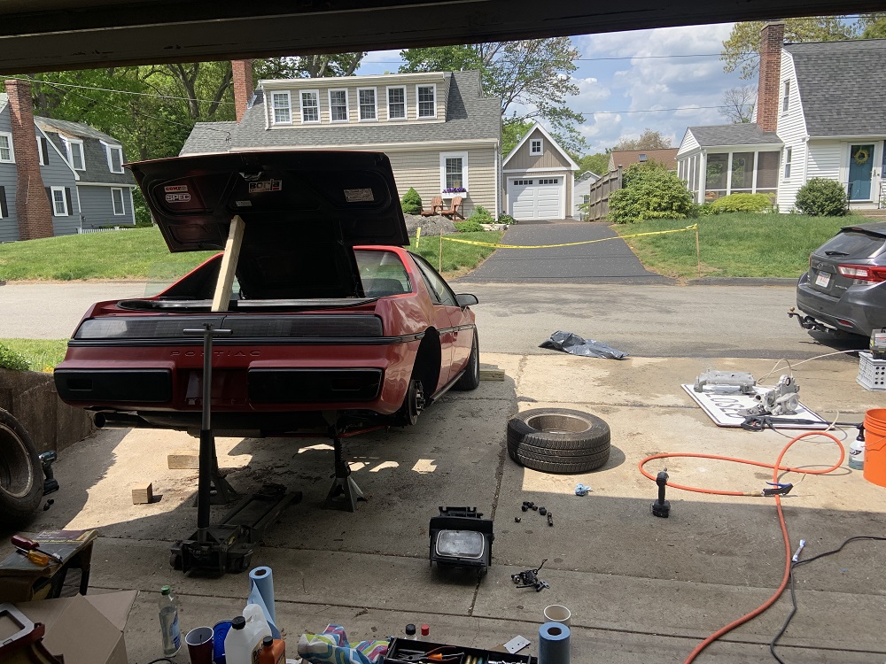
I cleaned up the garage too and pulled all the hazardous waste out to bring to the town hazardous waste center, and I pulled the Fiero in. It had to be turned around and a cop tried coming down the street immediately after I had moved the car into the road to do a 3 point turn with it, pulling it with the Subaru. He was really mad that he couldn't get by, it was the first time a cop hadn't been excited to see the Fiero. He was young though, and I generally have unpleasant interactions with young cops, older cops are almost always cool.
I also got some LS exhaust manifold bolts from Summit, they fit perfectly, I tried them out with the header flanges from OSHcut, they fit good, but they are able to be positioned poorly, I may try and put some bushings in two of the mounting holes to help with alignment, otherwise they seem great.
progress is looking good! are the bolt holes for the flanges too big? I intentionally made them large so that thermal expansion wouldn't put excessive shear on the bolts. maybe I made them a bit too big.
------------------ "I am not what you so glibly call to be a civilized man. I have broken with society for reasons which I alone am able to appreciate. I am therefore not subject to it's stupid laws, and I ask you to never allude to them in my presence again."
progress is looking good! are the bolt holes for the flanges too big? I intentionally made them large so that thermal expansion wouldn't put excessive shear on the bolts. maybe I made them a bit too big.
A little too big for locating purposes, I will make some locating sleeves and verify that one or two of the holes could simply be made smaller to locate the flange precisely, no need to have all the holes be smaller. I would imagine maybe the center two holes (hole and slot) could be the locating features as thermal expansion would probably put the least shearing force on those, especially since one is a slot.
Alternatively I could just outline the bolt heads on the flange so I have a visual to line everything up to once they are headers.
[This message has been edited by zkhennings (edited 05-24-2021).]
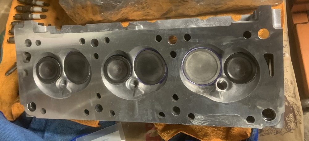
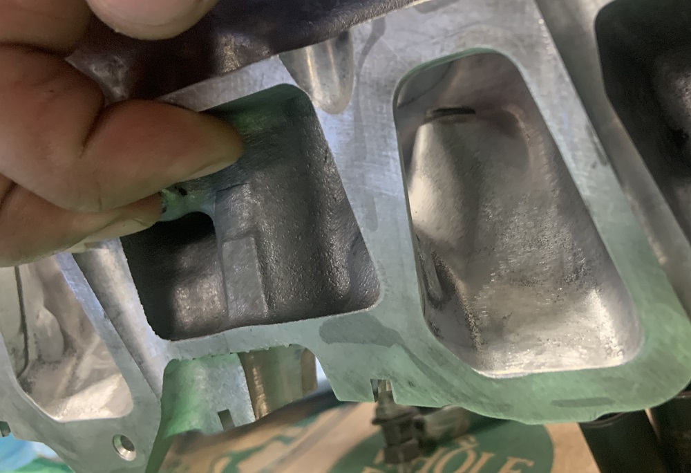
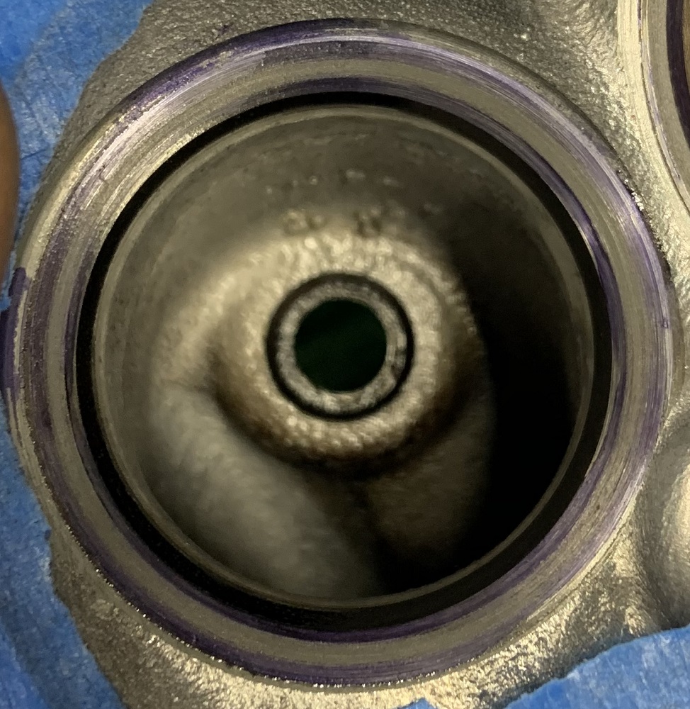
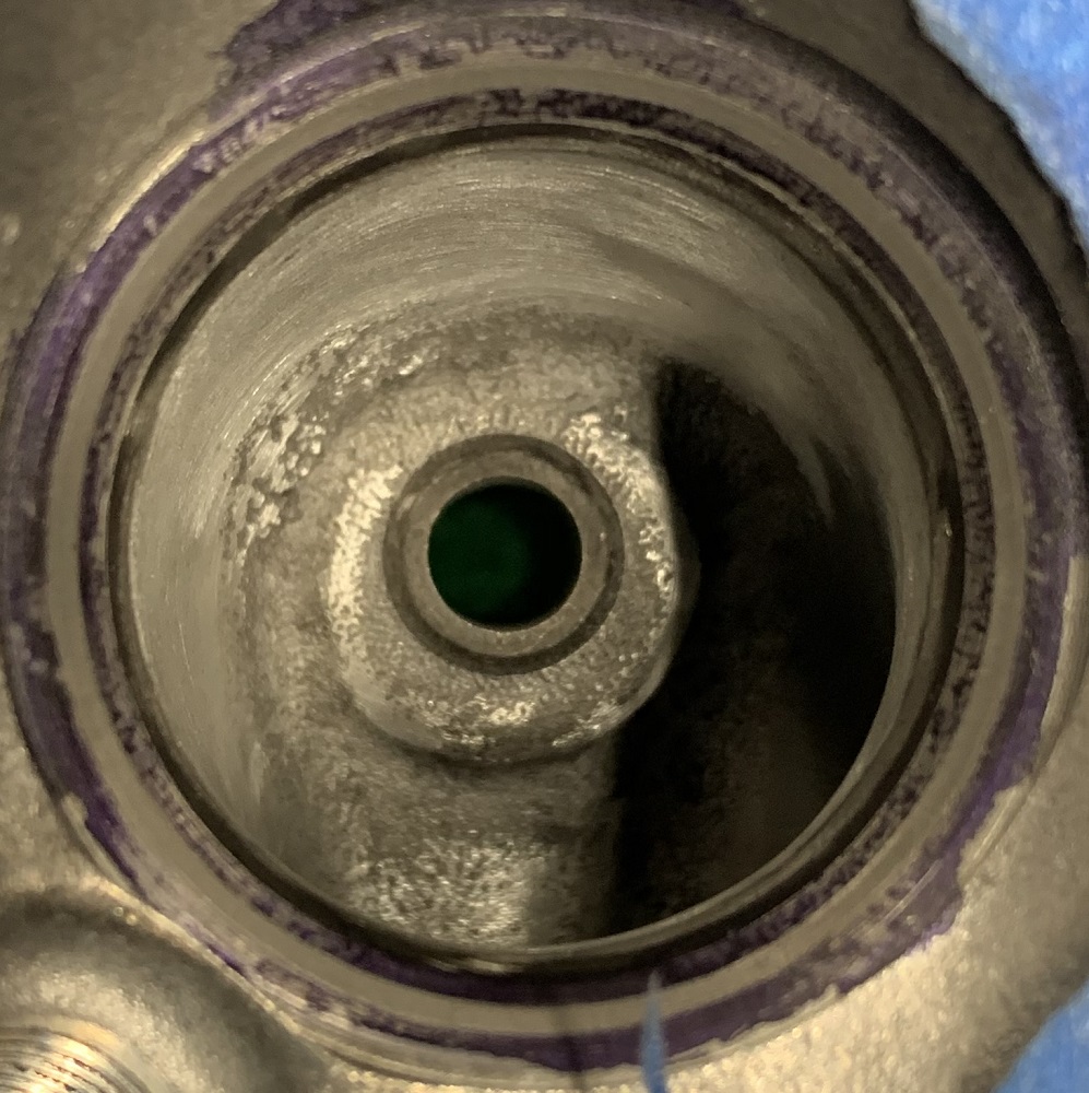
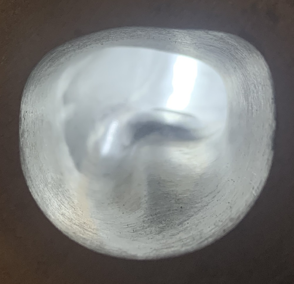
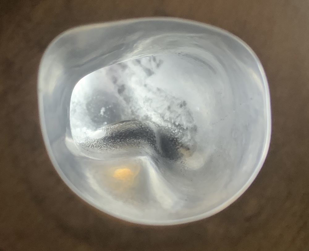
Spent some time "porting" one of the cylinder heads. I smoothed everything out with a pneumatic die grinder and sandpaper cylinders, got rid of any casting marks and sharp edges. I opened up the exhaust and intake bowls and really smoothed the short radius turns into the port. I did not gasket match the intake ports. I did have to use a carbide bit to get at some lumps in the exhaust bowls, the sandpaper cylinders were too wide.
Intake port
Exhaust port
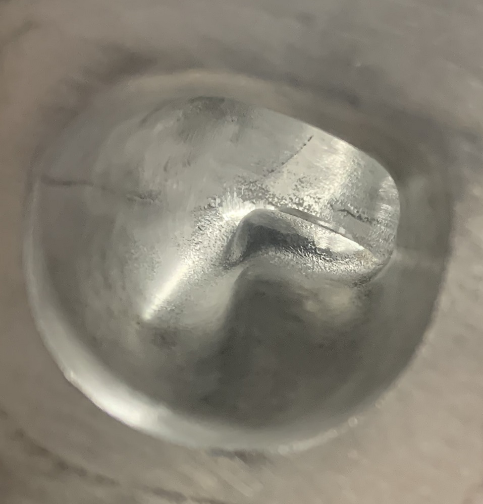
Intake bowl stock vs "ported"
Exhaust bowl stock vs "ported"
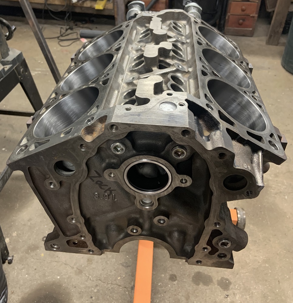
I used Scotchbrite Roloc Bristle Discs to clean up the engine block head sealing surface. They do a good job without removing any metal.
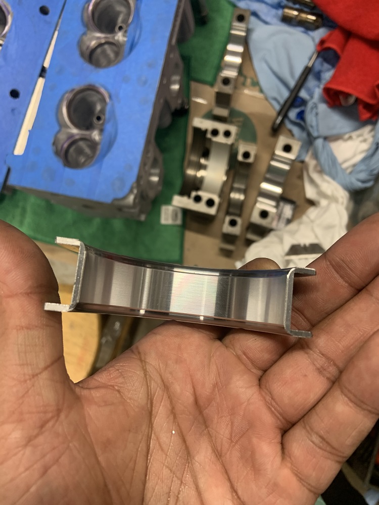
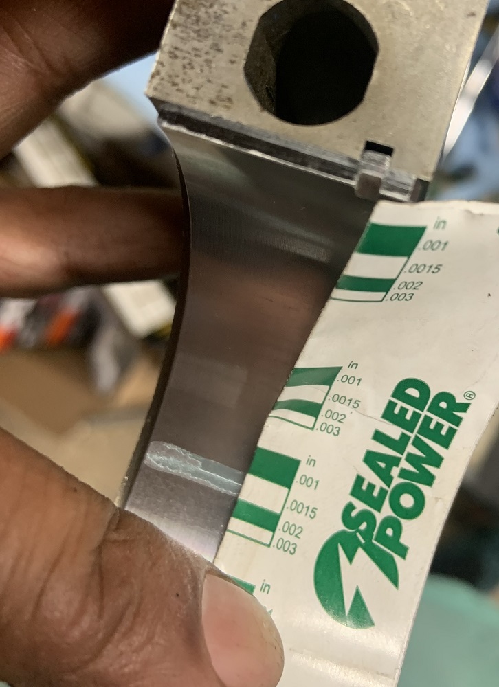
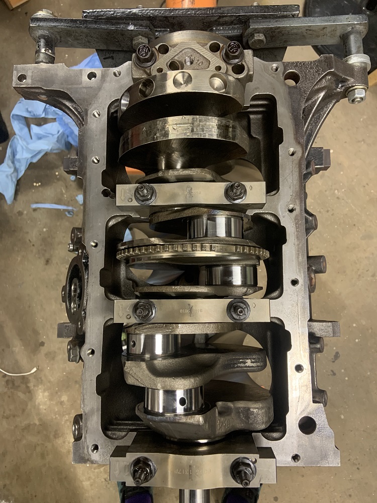
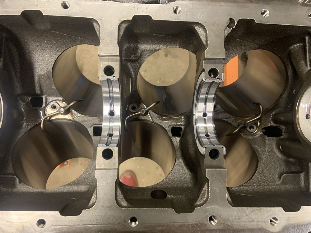
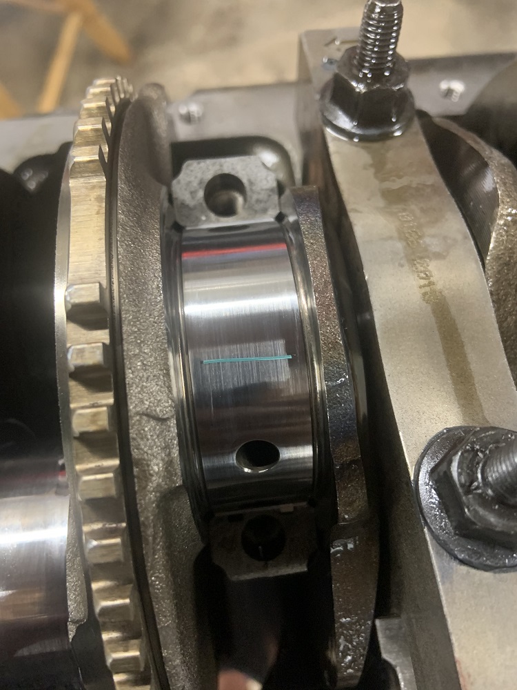
I checked the bearing clearances for the crank too, main bearing clearances are supposed to be 0.0008-0.0025in, and thrust bearing clearances should be 0.0012-0.0030in.
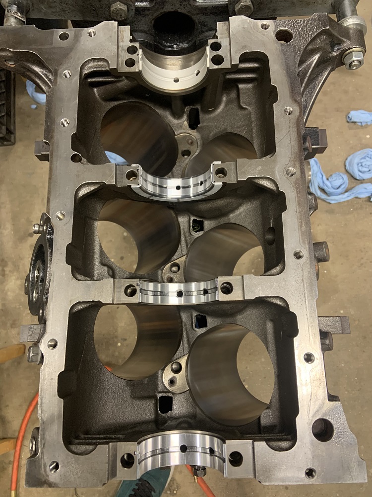
I installed the main bearings into the block
The bearing cap bearing for the thrust bearing was missing the locating tang
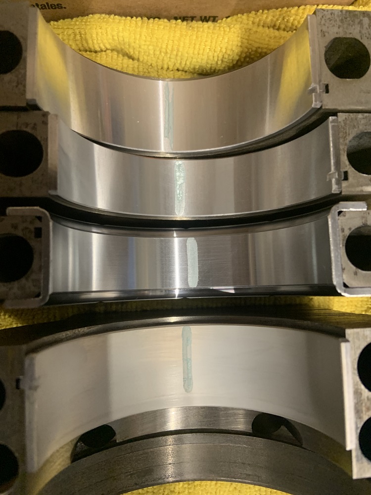
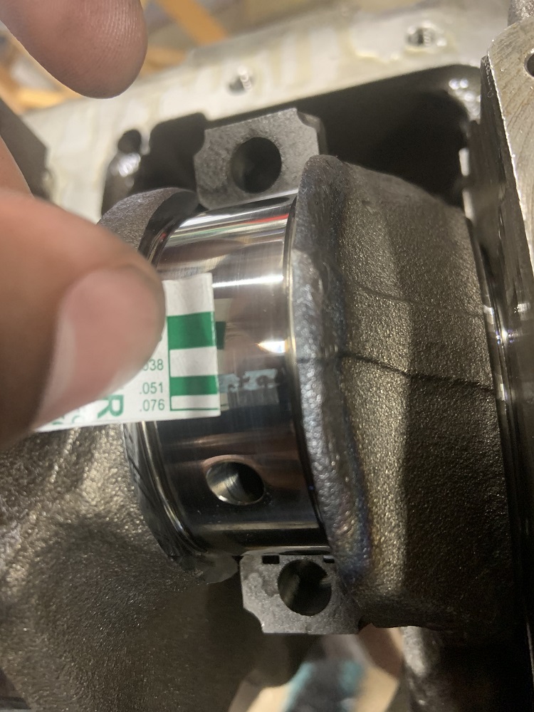
But on MAHLEs website they say it doesn't matter, and with the thrust bearing the tang serves no locating purpose. So I went ahead and installed it. I torqued all the main bearing caps to 37ftlbs and then gave them all an additional 77*. Took it apart to measure the bearing clearances. All the bearing clearances were very close to each other.
They all measured out around here
Somewhere between 0.0015" and 0.0020". I had gotten some plastic razors to scrape the plastigage off the bearings, but it did a terrible job. Brake clean and a microfiber towel did a fast and thorough job.
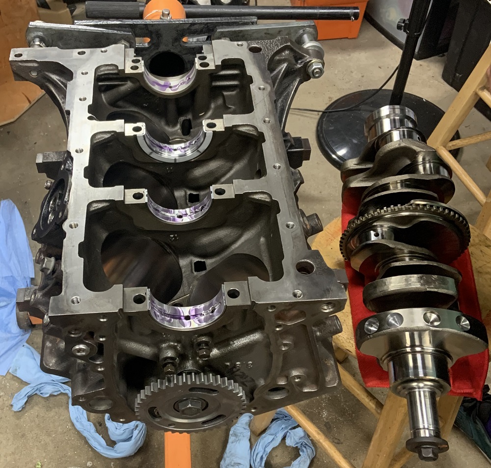
Crank ready to be installed with Royal Purple assembly lube. I hadn't smeared it yet here and I smeared it on the sides of the thrust bearing as well.
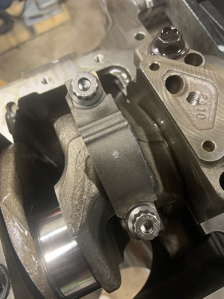
Installed and torqued. I put some Subaru Fuji Bond (3 Bond) on the rear of the rear bearing caps mating surface per the service manual.
I have been waiting on the remaining valve locks from Summit for weeks and they are telling me they won't ship until end of June. The manufacturer recommended me to a different supplier and they are now arriving today. Just have to finish porting the other head and I can get the heads all together.
Pistons will be going in soon.
[This message has been edited by zkhennings (edited 05-26-2021).]
on a 2.8, this is easy enough, on a later FWD engine, with the FWD timing cover, it gets a little harder, as the balancer is also the crank pulley. one for a gen II SBC may work, if they're even offered. measurements would need to be taken to make sure everything fits as required, and I would also contact someone at ATI prior to purchasing and asking about using it on a 60V6 prior to purchasing, as I'm sure there's a ton of engineering tied up in a balancer beyond basic fitment.
Well Eric I was able to tell the difference right away. And the 3.4L and 3.7L have inherited the same balancer and it still works flawlessly! The good thing about these balancers is that they can be tuned to different frequencies and they are fully rebuildable.
Would this one fit the snout specifically? I am not sure if they make a serpentine version for the SBC. I would have to call them to discuss the depths I would be looking for as they offer this one in a few different depths. I may have to machine a longer one down to the right depth if everything else checks out. Realistically I will probably run the factory balancer for a bit and see how it goes, it will be a street car the majority of the time and I would like to do some autocross and maybe see how it does at the drag strip. But it is something I will be looking for if I ever do lightweight internals and higher compression and try to push the RPMs a bit more.
Well Eric I was able to tell the difference right away. And the 3.4L and 3.7L have inherited the same balancer and it still works flawlessly! The good thing about these balancers is that they can be tuned to different frequencies and they are fully rebuildable.
I didn't say it wouldn't work, I said it's easier with the fiero timing cover d/t belt requirements. Feeling better doesn't mean optimized either,
quote
Originally posted by zkhennings:
Would this one fit the snout specifically? I am not sure if they make a serpentine version for the SBC. I would have to call them to discuss the depths I would be looking for as they offer this one in a few different depths. I may have to machine a longer one down to the right depth if everything else checks out. Realistically I will probably run the factory balancer for a bit and see how it goes, it will be a street car the majority of the time and I would like to do some autocross and maybe see how it does at the drag strip. But it is something I will be looking for if I ever do lightweight internals and higher compression and try to push the RPMs a bit more.
The Gen II SBC used a balancer similar to what the FWD 60V6 engines used, something like this
I might call ATI next week and ask about using one with a V6, it would be nice to have a rated balancer.
------------------ "I am not what you so glibly call to be a civilized man. I have broken with society for reasons which I alone am able to appreciate. I am therefore not subject to it's stupid laws, and I ask you to never allude to them in my presence again."
I might call ATI next week and ask about using one with a V6, it would be nice to have a rated balancer.
I know what they are going to tell you, "We don't know and it will not fit". But if you tell them you want to send a balancer to get tuned to an engine they will do it for you. So, my advice is that if that ribbed damper has the dimentions of the snout, get it and I can guarantee you it would work. If you want it tune to specifally to the frequency of your engine then you can order a tune up kit for your frequency, just different "O" rings. How do I know this? Because I called them 8 years ago when I got mine and they said it wouldn't work and it did for me.
Now, as far as the "feel doesn't mean is right" thing, tells me you don't have a highly tuned "BUTT" dyno like me.
I don't think Eric is saying you aren't correct or that it isn't helping dampen your engine vibrations, he is just saying that when it comes to optimizing the performance and getting it to be the best it can be, it might take a little more than feel, even though your feel is better than most. Some accelerometer data or equivalent would give you a more complete picture, and is what the manufacturer is going to use to tune the dampers for specific setups.
But like you said, if they do not have the data already for the application then they may say it is unsupported, and feel may be all you have to get it as dialed as possible. And like Eric said, having a balancer that is rated for the abuse is worthwhile already even if not tuned to maximum potential.
I done goofed and was looking at the metric specs for ring gap when setting ring gaps but measuring in thousandths.... I had taken a pic of the service manual page with my phone and it is the tiny pics fault hah. I should have noticed that it was a full decimal place off of what I was measuring, but long story short I gapped the first ring to 0.0015" (metric value was 0.15mm) instead of leaving it alone and having it be in the correct range of 0.0006 to 0.0011". Unfortunately had to order another full set.
Edit to say I also put in an order for all of my connectors from Ballenger Motorsports, the TPS connector is for the N* TB, the alternator connector is for the 99 Astro, and the air temp connector is Fiero style, but I ordered a fast response air temp sensor. Probably unnecessary for an NA application but hey you never know. Also put in what should be a final RockAuto order for odds and ends, but ordered a new TPS, new MAP sensor, and new crank position sensor. I figured I would rather start with new sensors when getting this thing tuned.
[This message has been edited by zkhennings (edited 05-28-2021).]
I had been holding out to update until the heads were installed, but my backlog of pictures was getting too long so here we go.
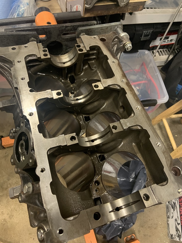
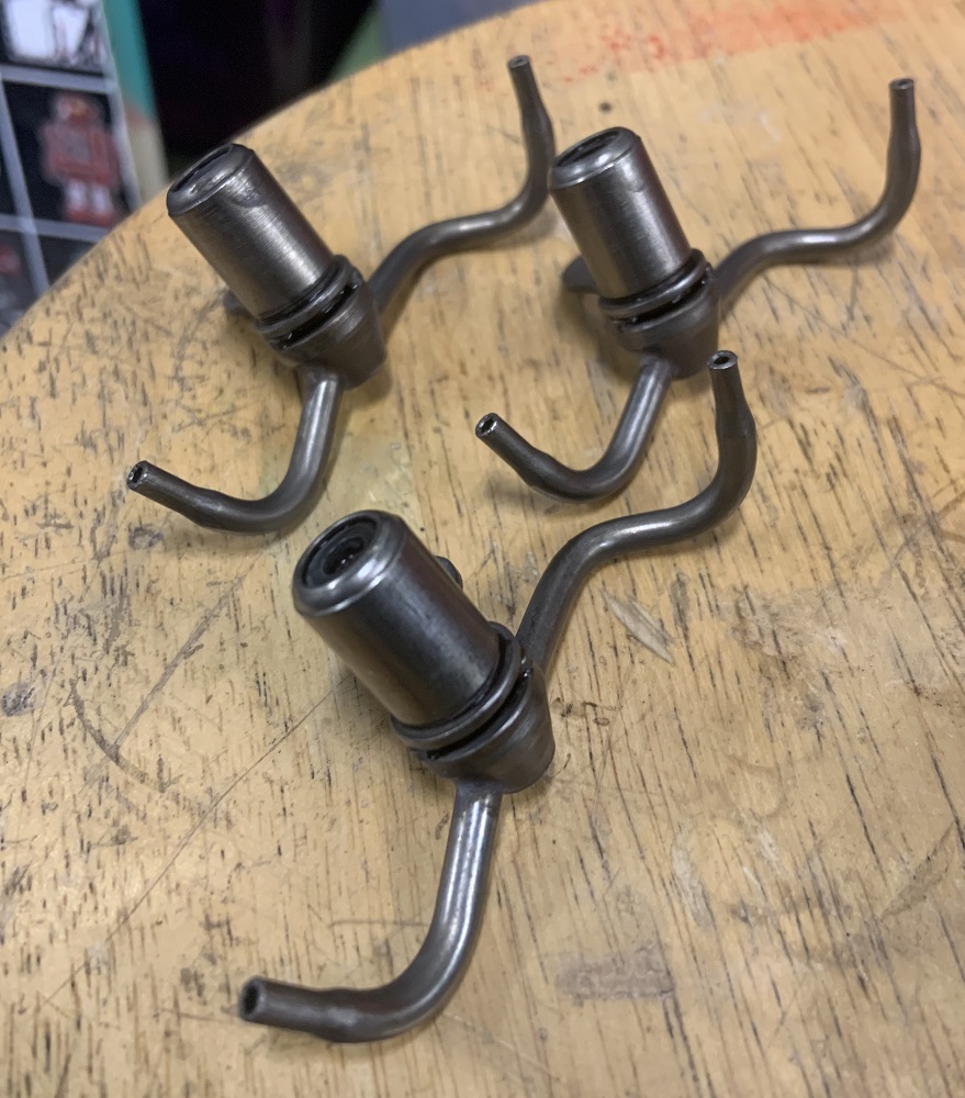
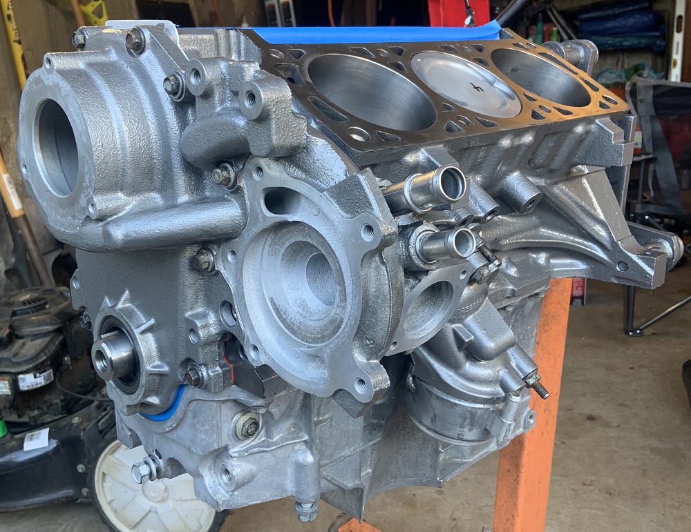
I did not realize the piston squirters needed to be installed prior to the crank, it appears doable but there is no good angle to tighten the bolts with the crank installed so out it comes.
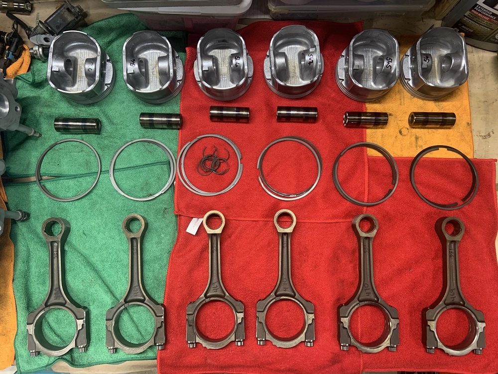
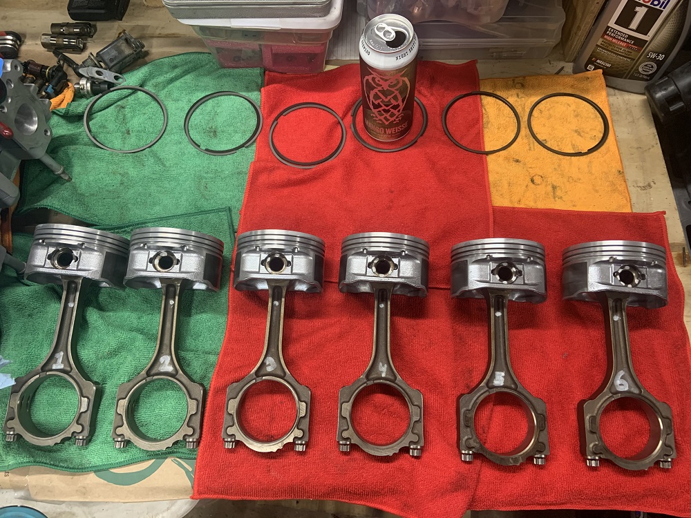
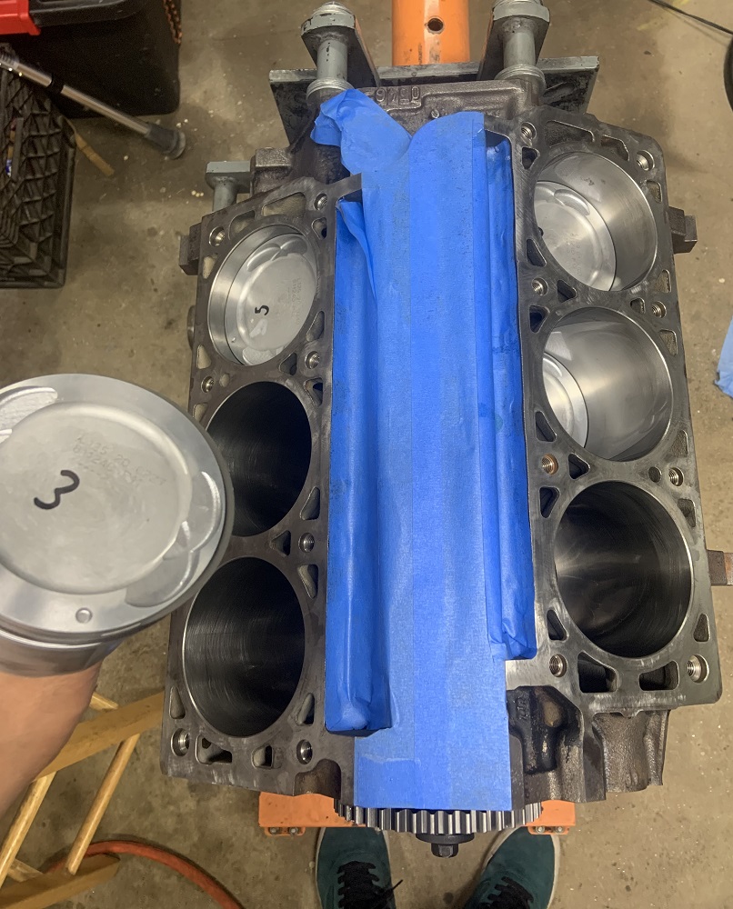
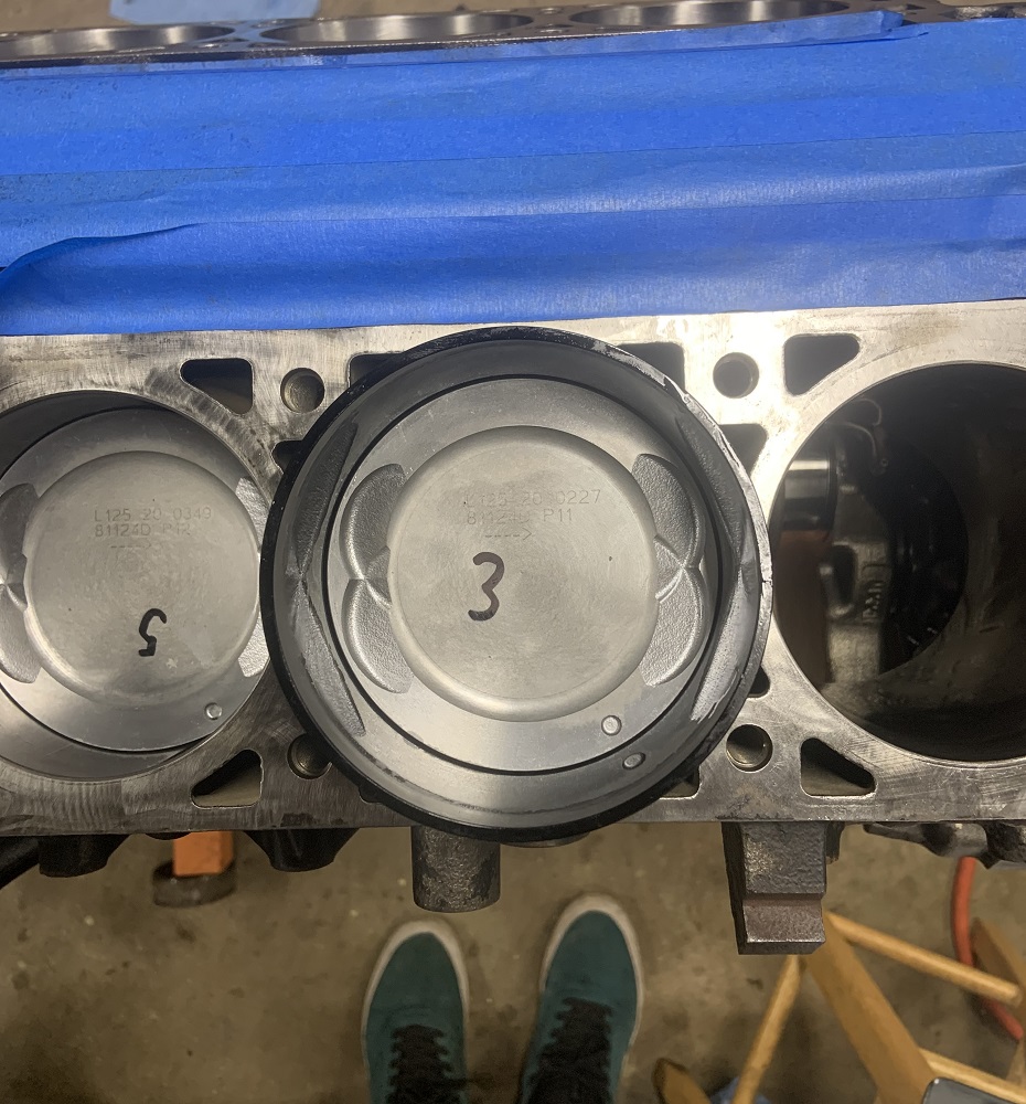
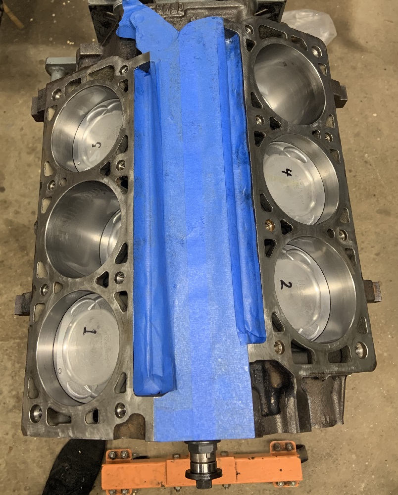
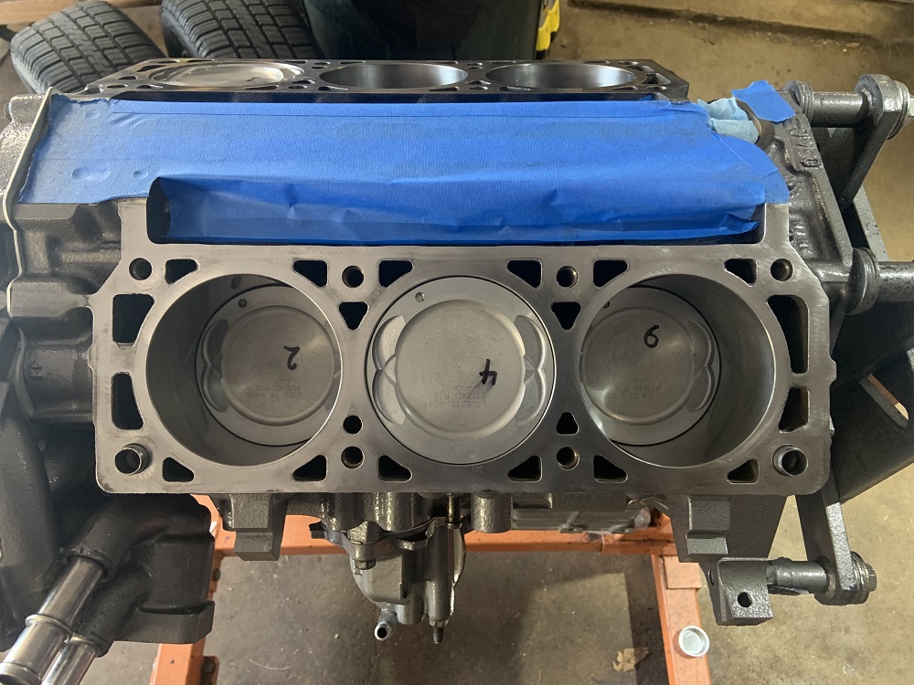
Assembled the pistons and rods and checked the gap on all the rings including oil scraper rings. Rings were all installed with any markings facing up. Factory manual gave a wide range for ring gap spacing so I set them all on opposite corners.
I plastigaged all the rod bolts, I think the 40ftlbs with ARP fasteners and ARP install lube puts them around where the factory bolts would be compressing the caps as all of the rods were in spec at the larger end of the clearances.
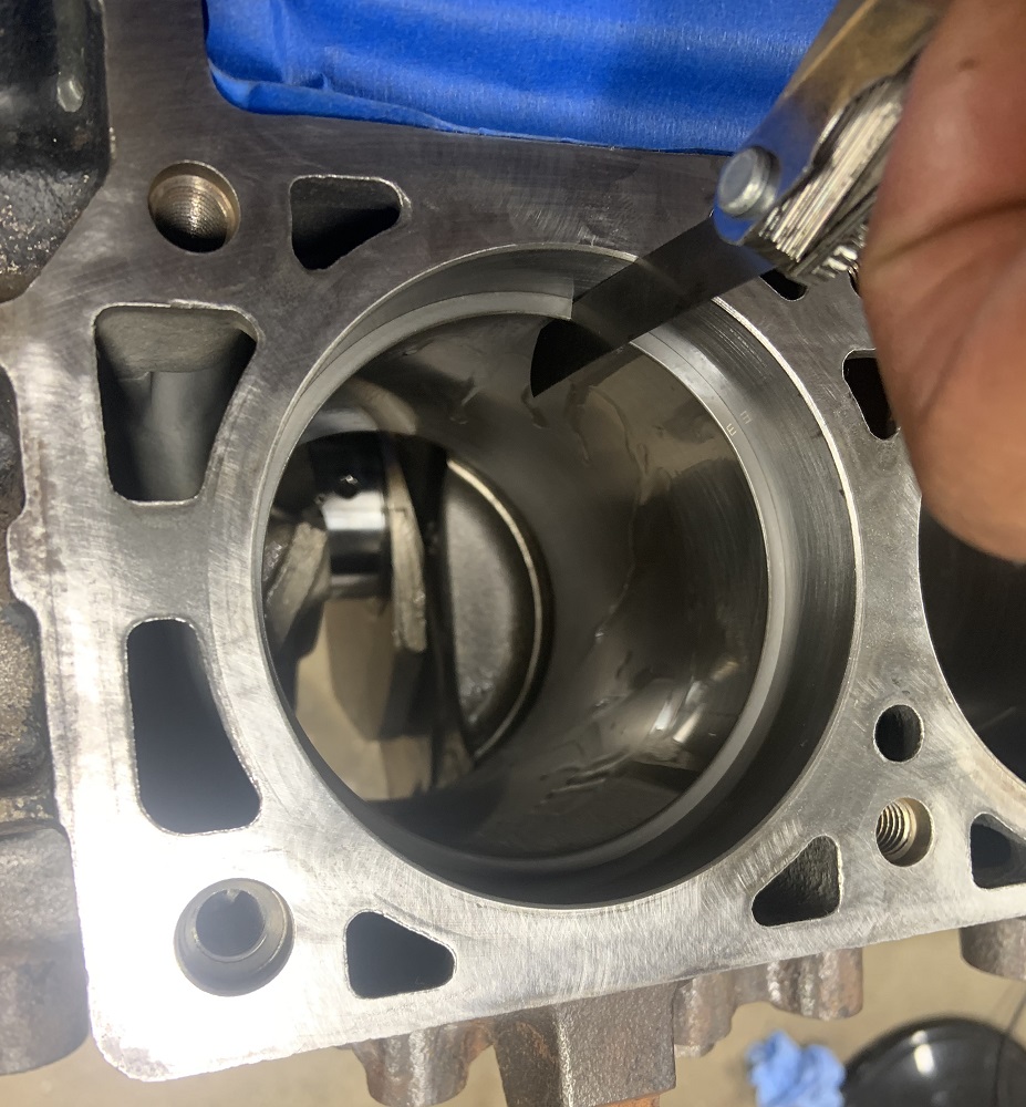
I installed the pistons with the tapered ring compressor and some 5w30 oil, the tapered ring compressor is well worth the $39 it cost me.
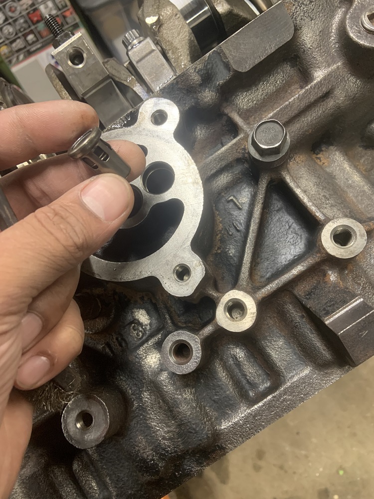
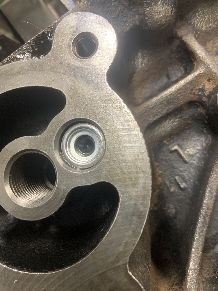
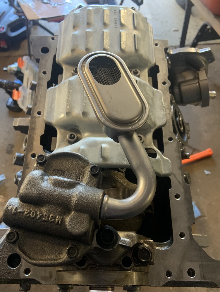
I installed a new oil bypass valve into the block
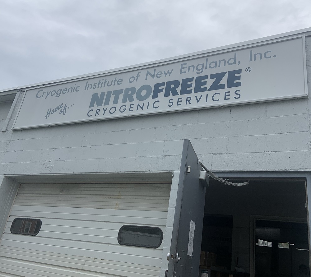
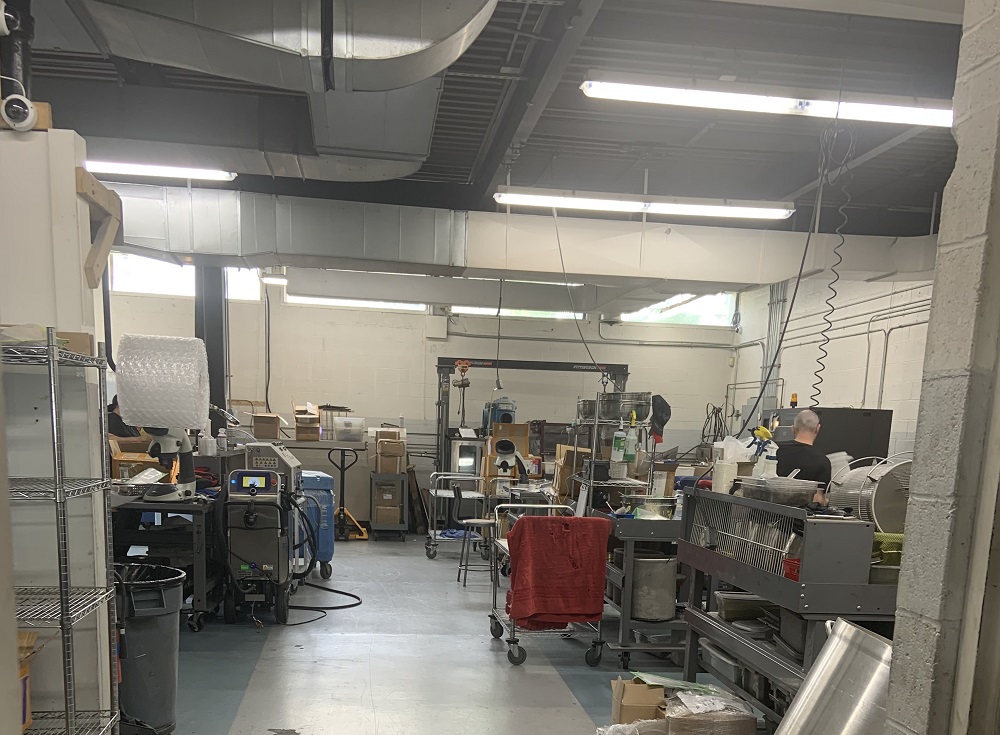
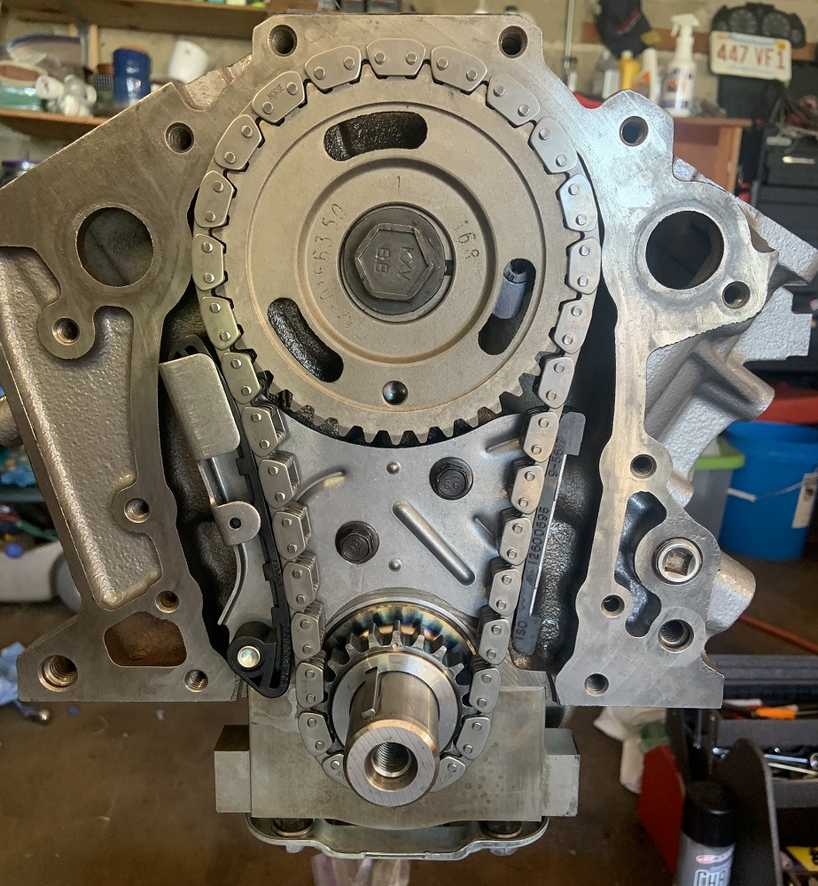
I took the timing chain, sprockets, and the rocker arms to the Cryogenic Institute of New England in Worcester, it was well priced at $75 for everything, the process ran for three full days. I will be going back with possibly some transmission parts in the future.
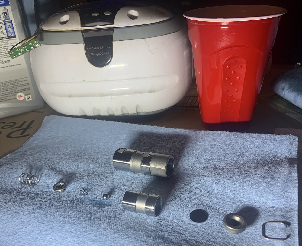
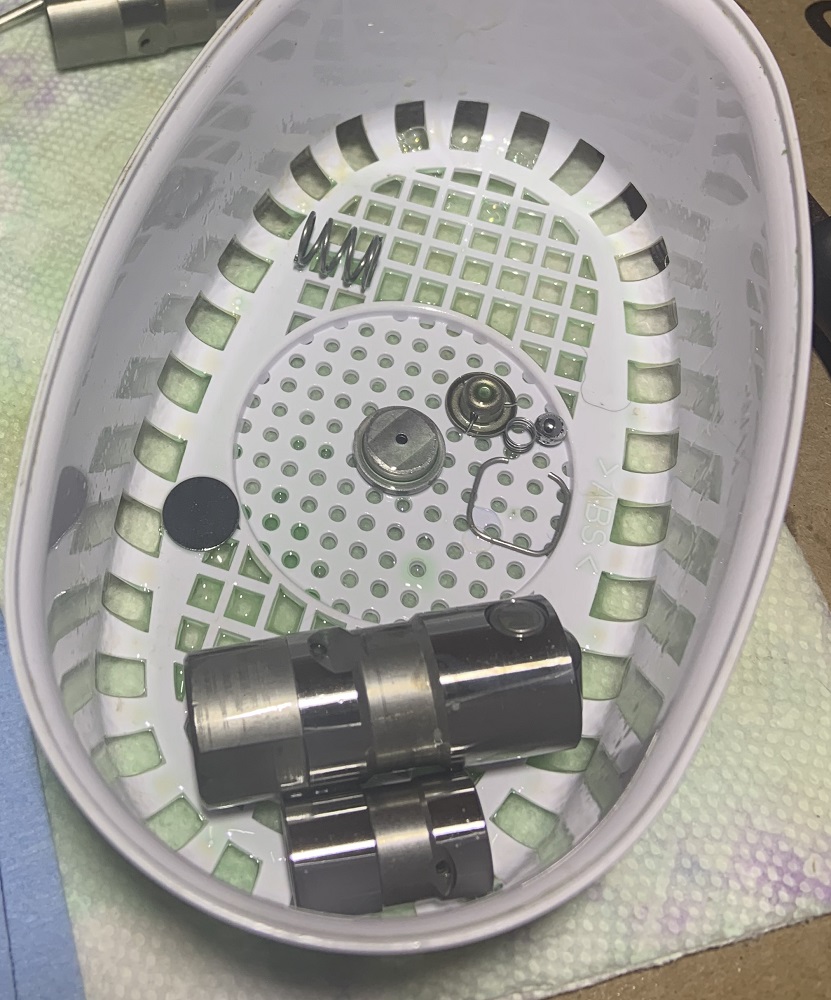
I spent some time disassembling all the new lifters that I bought, they were a little dirty so I figured I would take them apart one by one, run them through the ultrasonic parts cleaner a few times in some Simple Green, then oil them and put them back together. They have been sitting submerged in a container of oil for days. A lot of particulate came off in the ultrasonic parts cleaner, I am glad I spent the time to do this, it took many hours. A good tip for taking them apart and reassembling is to use an allen key or drill bit etc to depress the little ball check valve, it allows the body to slide out of the housing easily, and same thing when assembling and trying to get the clip into place, depressing the check valve allows the body to slide fully into the housing.
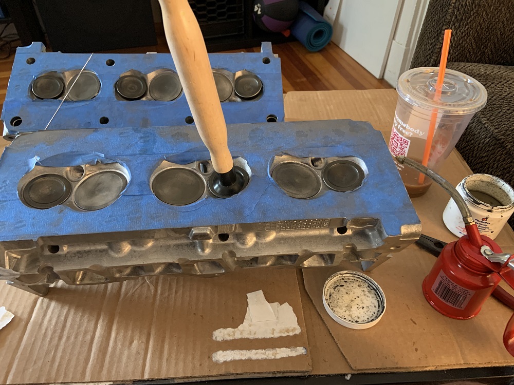
I also ported the second cylinder head and then spent a while getting all the ports in all the heads the same. I then hand polished all of the exhaust runners to help prevent carbon build up. It always builds up where the heads meet the headers, probably because there is a step in size that causes some turbulent flow and deposits carbon. The polishing will help prevent the carbon from being able to stick.
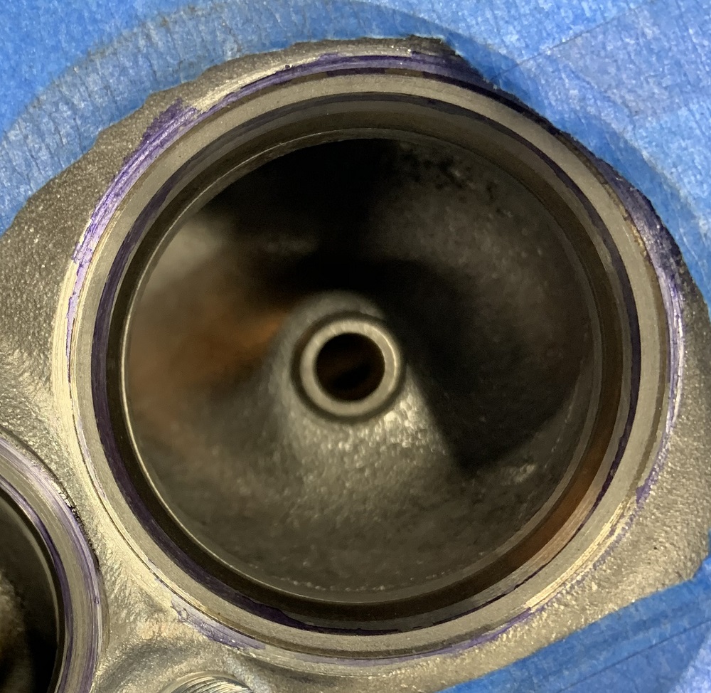
An unpolished but ported exhaust runner.
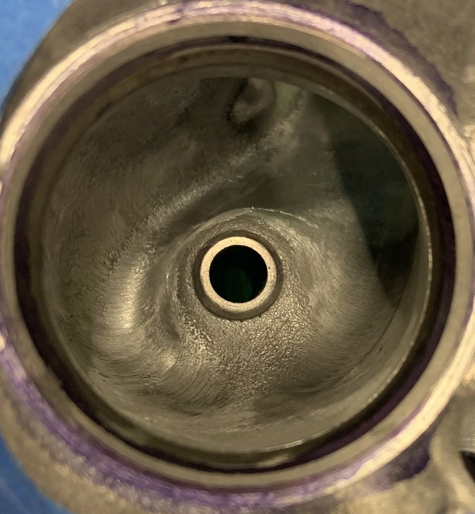
A polished exhaust runner. I started with 400 grit and worked up to 2500 grit sandpaper.
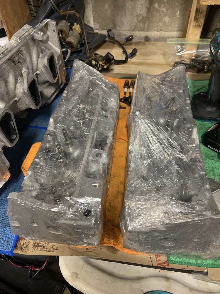
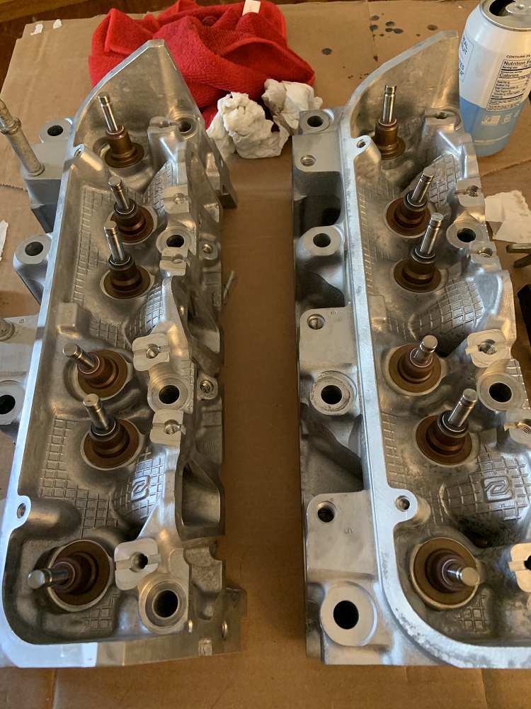
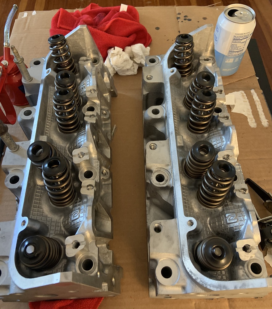
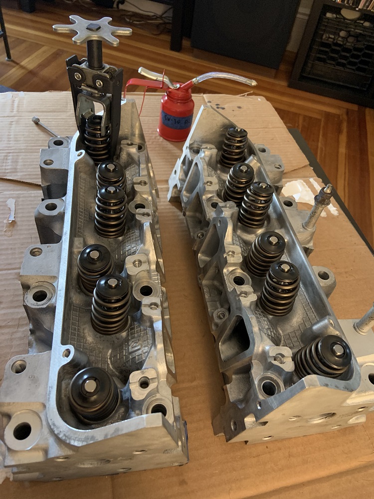
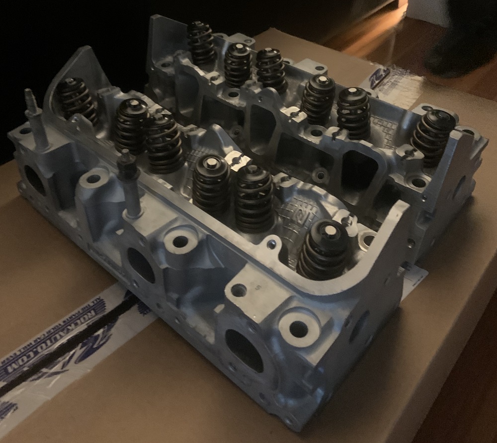
I washed the heads thoroughly, and cleaned out the valve guides with a little cylindrical brush and rubbing alcohol. I tossed them in the oven on the lowest setting with the door cracked until they were nice and hot to the touch to make sure all the water evaporated from the cleaning process. Then I decided to re-lap all the valves as all the porting, metal dust, and sandpapering probably affected the sealing surface of the valves. I assembled the heads with the PAC spring, keepers, and retainers.
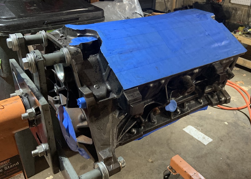
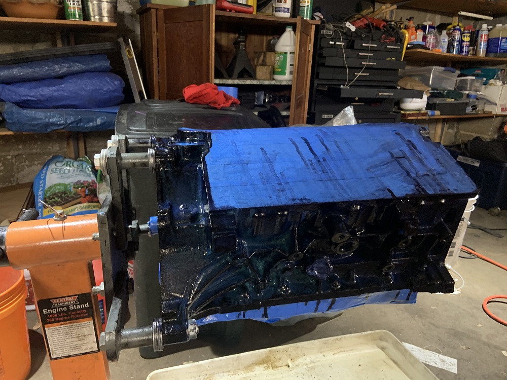
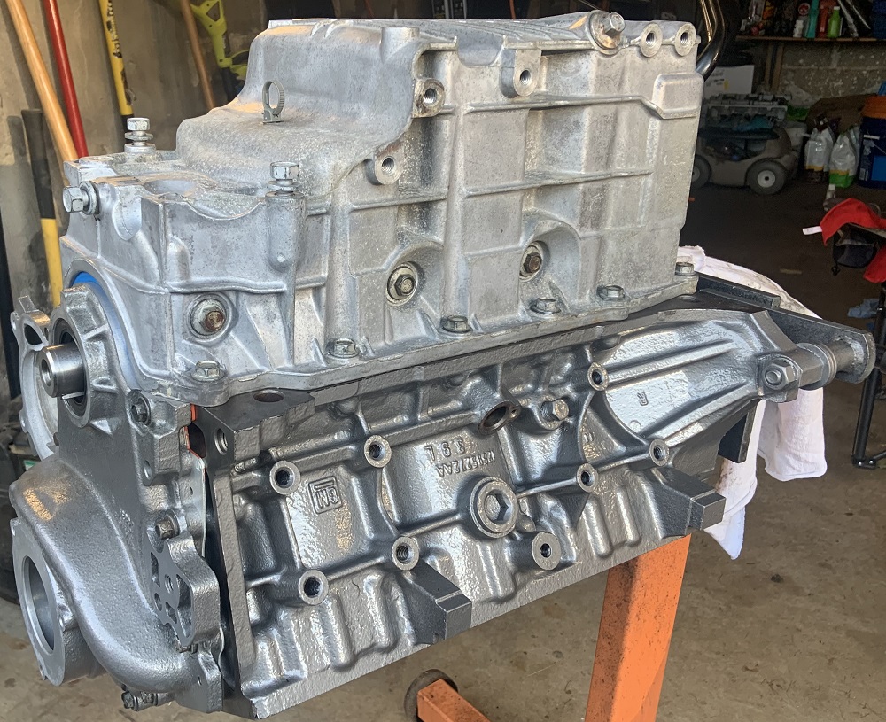
And finally I wanted to spray the block to paint it instead of brush the paint on, and I wanted to give a final sprayed coating to all of the parts I had already painted to get a more metallic finish. I was going to assemble everything and paint it all together instead of masking things off, but I still had to prep the block with an Eastwood rust converter so I had to end up taping the block off anyways for that. It was weird, it was sprayed out of a regular spray bottle where the trigger pumps the contents, but it was basically paint. It came out blue and dried black on the block. I sprayed one coat on the block and did not like the finish so I brushed it smooth, and then did a light second coat that I brushed on. It dried black but I have to wait 48 hours before I can top coat it, hopefully this weekend. My brother used to work at an autobody shop in highschool and he gave me a good tip for masking parts, which was to use a breakaway style razor blade so that when it dulls quickly and starts to tear the tape instead of slice it, you can just break the tip off and have a fresh razor again. Taping went much faster than when I taped all the other engine components.
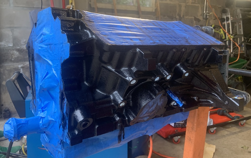
And here is the block painted with the rust reformer.
Once the painting is complete, the rest of the engine assembly will begin, and hopefully I can get this thing mounted on the cradle ASAP to begin mocking up fuel lines, wiring, exhaust, and the alternator location and belt routing.
[This message has been edited by zkhennings (edited 06-11-2021).]
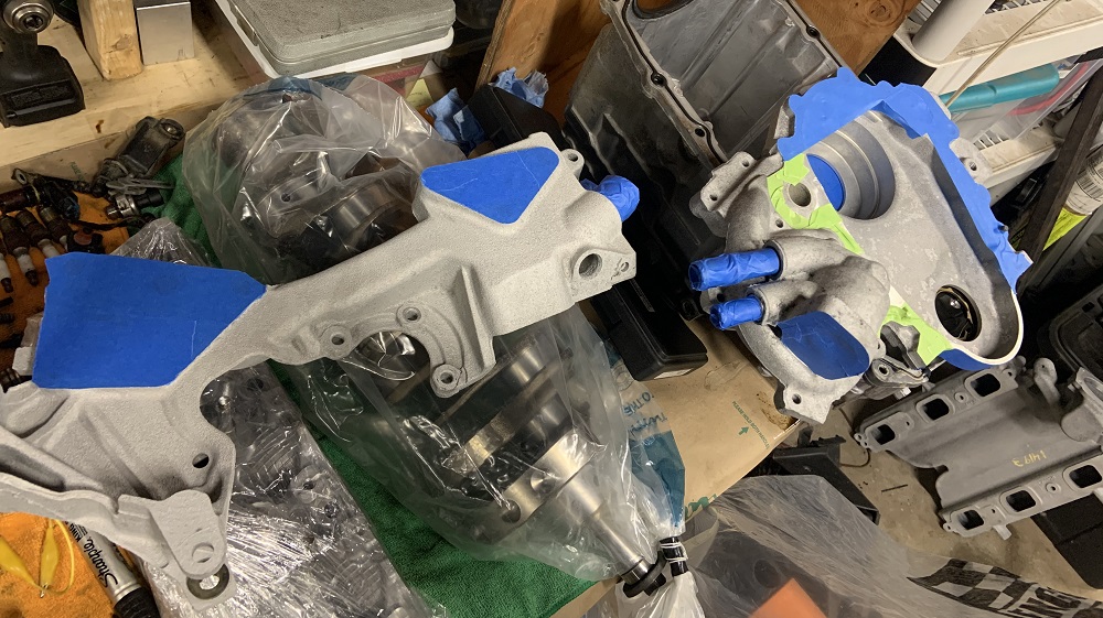
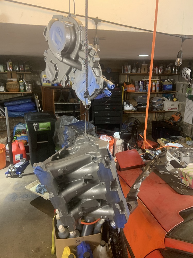
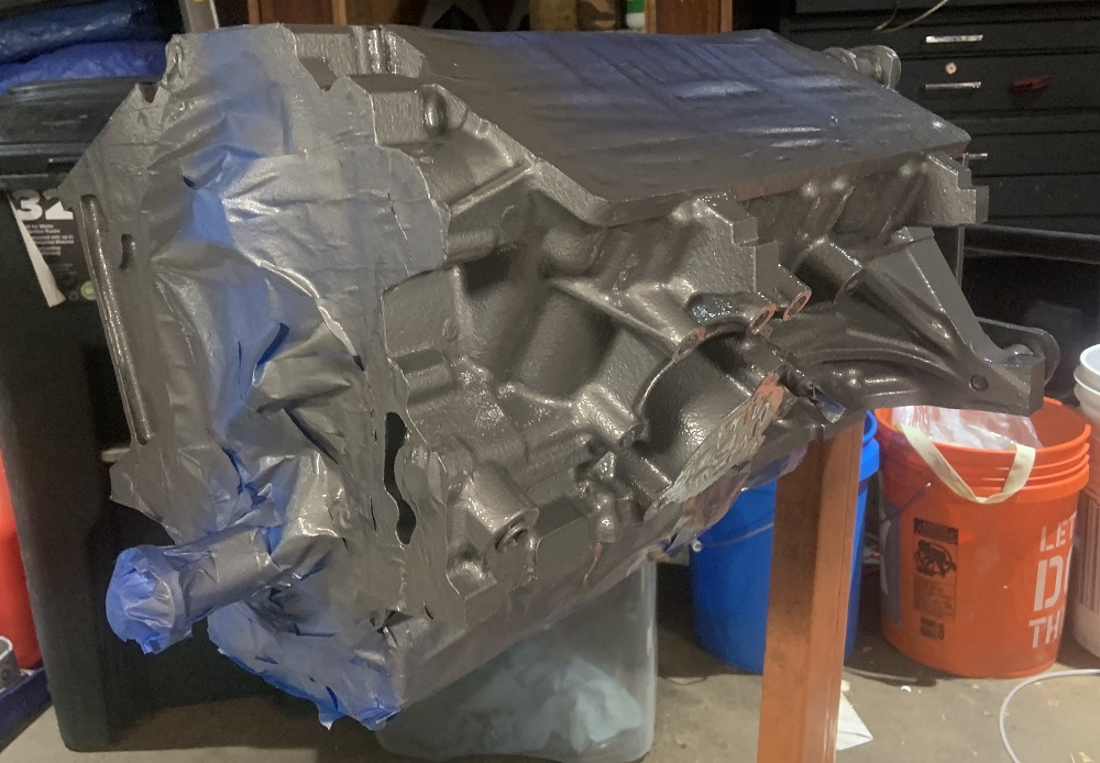
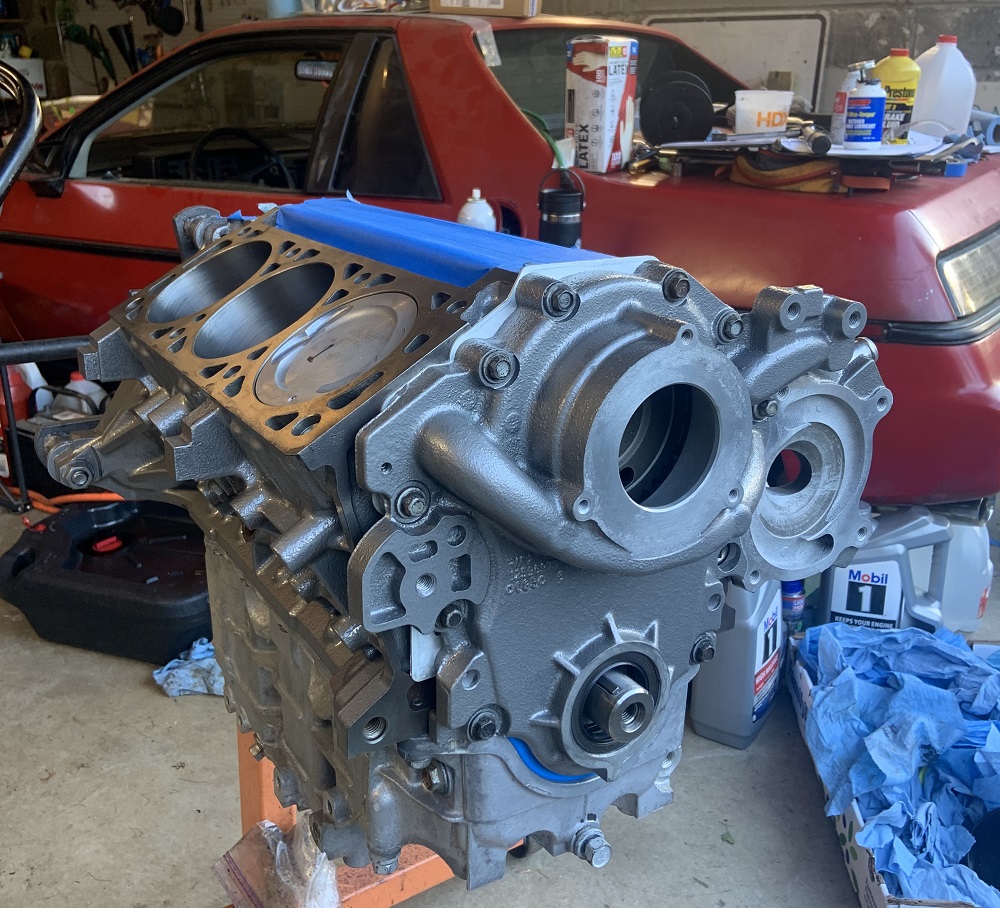
Little update from yesterday, got the painting of motor parts complete. I shot the paint out of an HVLP gun to paint the block as well as repaint the timing cover, coolant crossover, LIM, and oil filter adapter.
The rust converted block actually looked really good, and next time I paint a block I may consider just painting it black even though it makes it harder to find leaks.
These are the parts that brushed, waiting for spray. If you look at the timing cover you can see how the metallic came out real uneven when brushed on.
And here is everything drying, the hanging parts look like an art exhibit, they all come very close to hitting each other. The paint finish is very uniform now, I am looking forwards to seeing it all dry.
Finally done with taping and plugging for a while, each of those parts probably took anywhere from 30min to 45min to tape up and plug.
Next up is the remainder of the engine assembly.
[This message has been edited by zkhennings (edited 06-12-2021).]
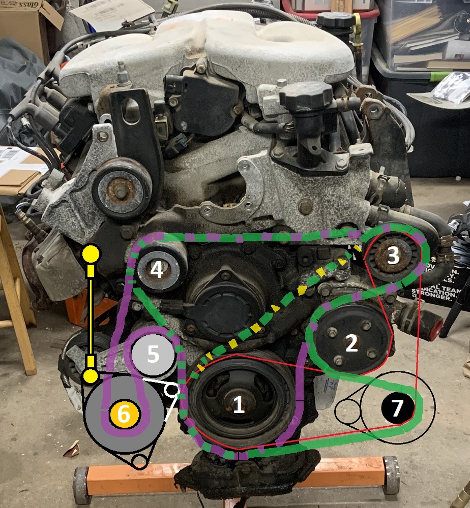
Thought about the belt routing some more, I think I will go with option purple, it leaves me open to add AC later as well. I will have to deal with pulley 3's location, I think it will need to be moved down and to the right to provide adequate belt wrap for the water pump. I could incorporate a belt tightening mechanism into that pulley as well, as it would be ideally positioned for it, and it is in a very easy to access spot. Otherwise I will use a rod end link on the alternator to tighten the belt as it is also a convenient location.
And since you can see the condition of the engine originally, here is the final paint finish for comparison.
to me, static tension with a belt that long seems like a recipe for belt slip, I would try and find a way to put a dynamic tensioner on it.
------------------ "I am not what you so glibly call to be a civilized man. I have broken with society for reasons which I alone am able to appreciate. I am therefore not subject to it's stupid laws, and I ask you to never allude to them in my presence again."
Are there AC/Powersteering delete options? Might save you a headache just putting in dummy pullies, then you get to keep the option of AC down the road.
I think you're right about the water pump though, under this arrangement I think it'd need more wrap.
I may replace pulley 4 with an automatic tensioner if I go purple route. I would put the pivot point right above the alternator. I could revert back to the initial red routing and tension that statically between pulley 1 and 7, or even put the stock tensioner there if I can fit it. We will see, I kinda doubt I will ever have AC in this thing, I don't know if its worth making my life more difficult now for a possibility that would require a ton of modification anyways.
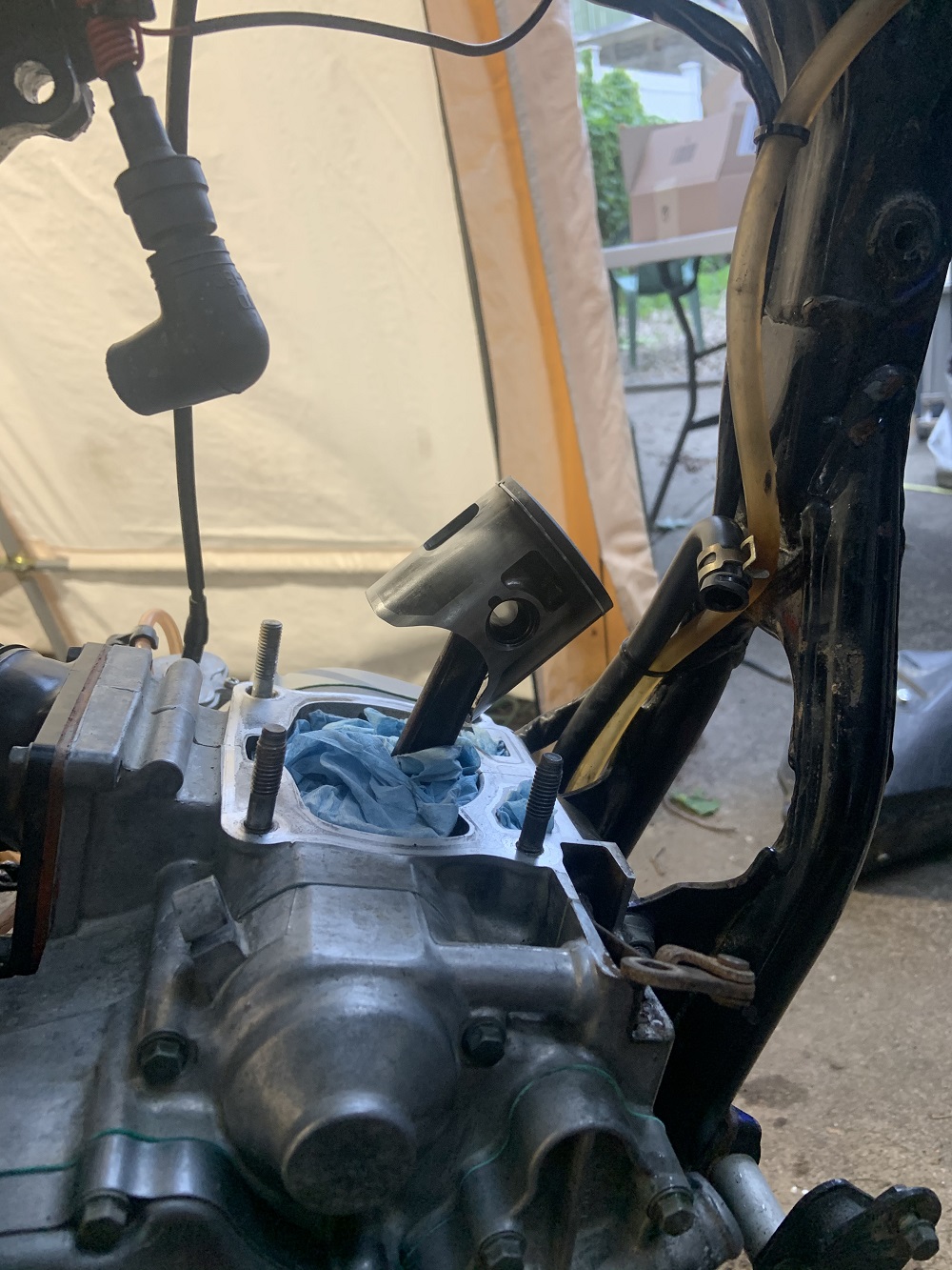
Been busy but fit some Fiero work in here and there. Had to rebuild my second YZ 125, this one an 04' (other one is 17'). Sprung a leak in a coolant hose and ran hot on the track, toasted the water pump gaskets and head gasket. Top end had just hit 30 hours so it was time for a new top end regardless. Also installing a new seat cover. Motocross bikes are by far the most relaxing machines to work on, everything comes apart and goes together so easily, and they are as simple as can be.
Bike stripped down
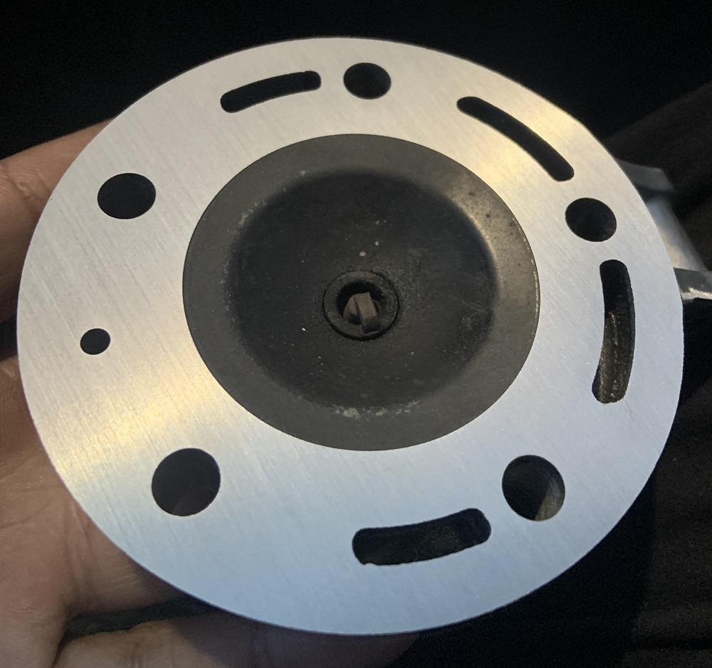
Head resurfaced on my calibrated granite block
Onto Fiero work:
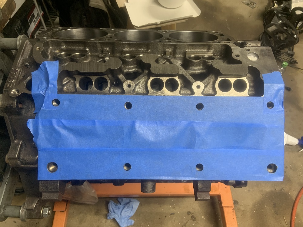
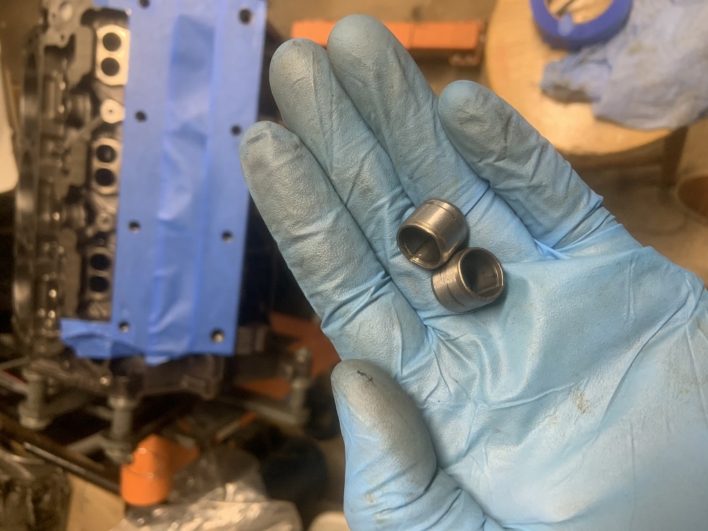
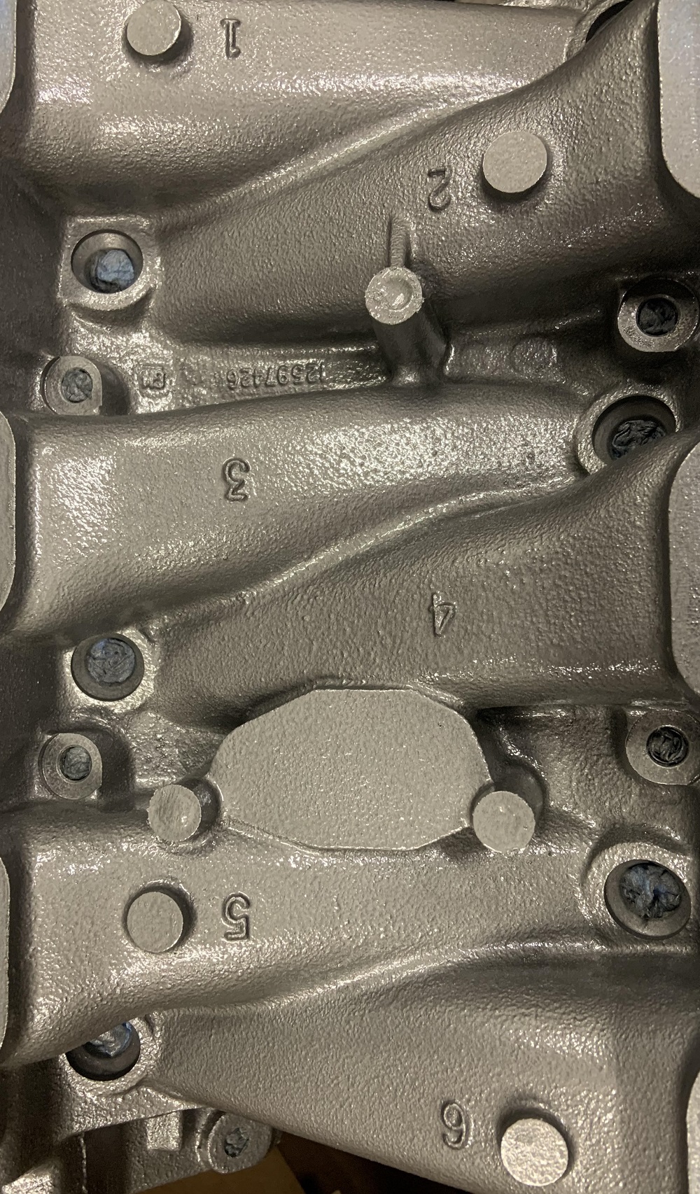
New dowel pins
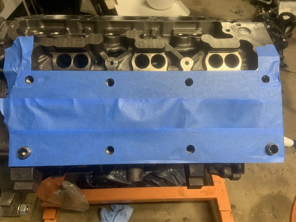
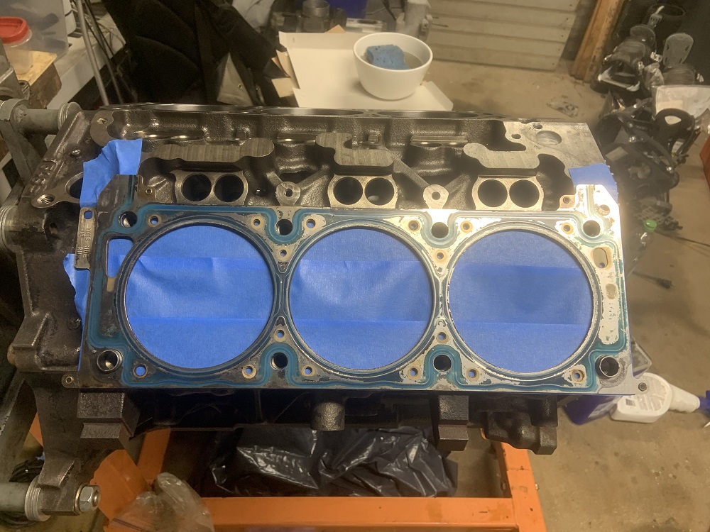
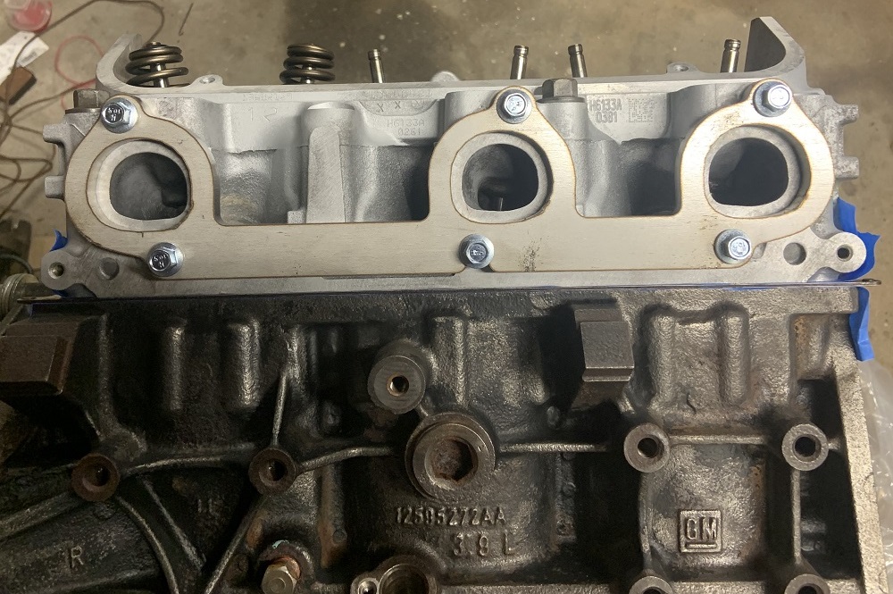
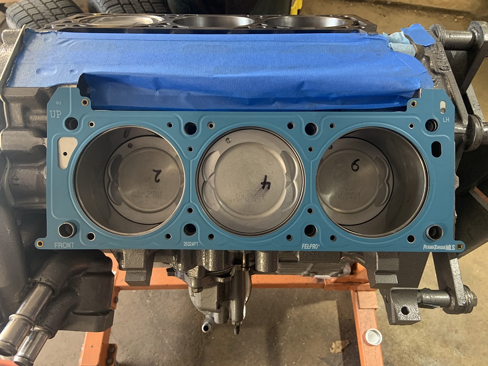
Felpro Permatorque MLS head gaskets installed
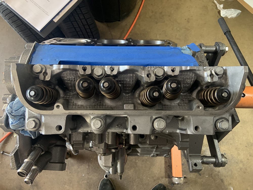
Head installed with new Felpro head bolts, used some ARP assembly lube.
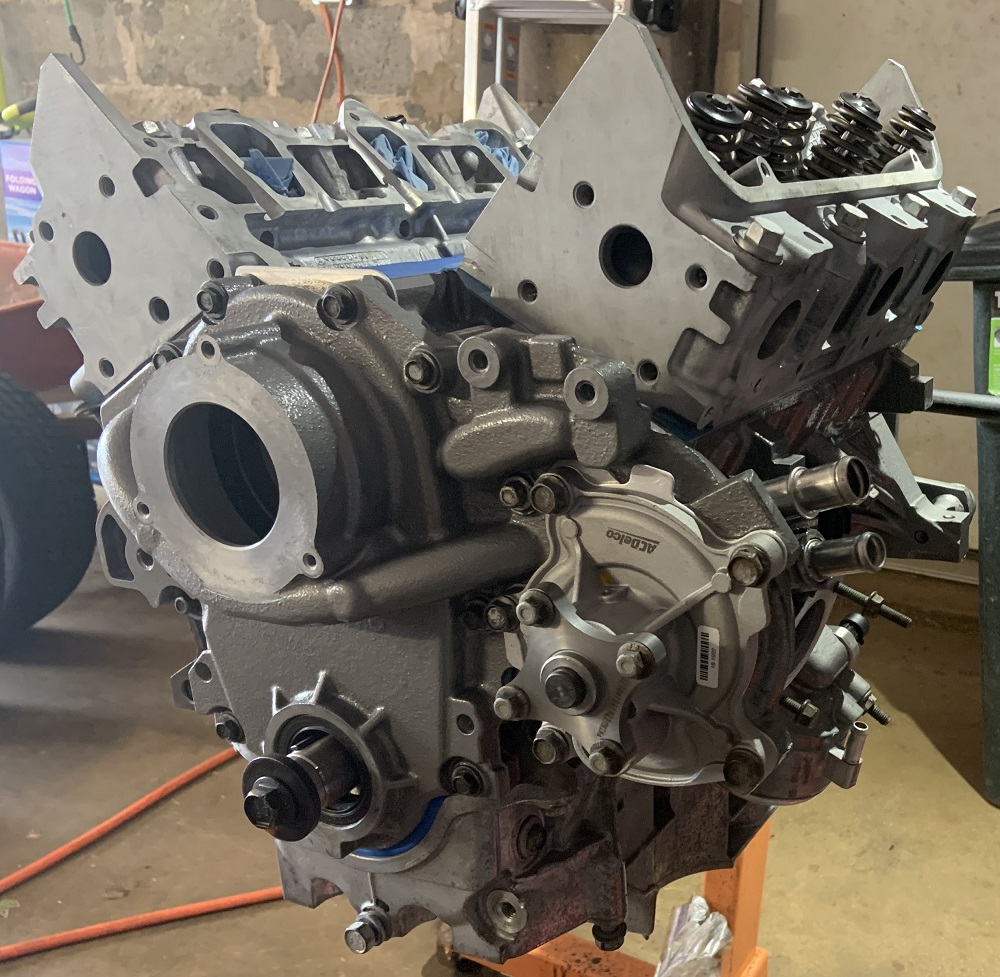
Both heads installed and new AC Delco water pump installed
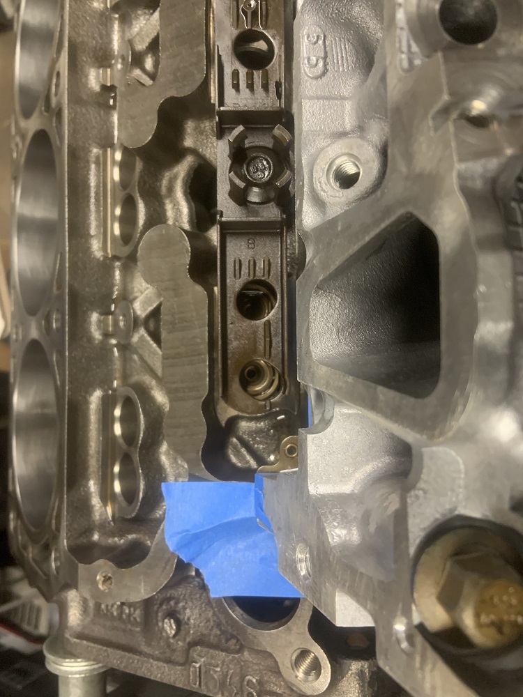
Coolant temp sensor installed with a new copper washer, new GM crank position sensor, and original knock sensor installed
Oil pressure sensor and other knock sensor installed
I am installing the knock sensors because I bought a KnockSense kit, it gives you a way to interface the knock sensors with the Micro or Megasquirt, and it also gives you an LED to install in the dash that will flash when it starts to knock. I got a shielded Y cable made and I have connectors from Ballenger for the knock sensors. I am not sure if I will have the Microsquirt interface with the KnockSense yet, but I will be able to form my timing table from watching the knock light and backing off timing when it knocks. If I ever go turbo the KnockSense will definitely interface with the Microsquirt.
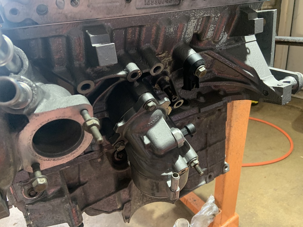
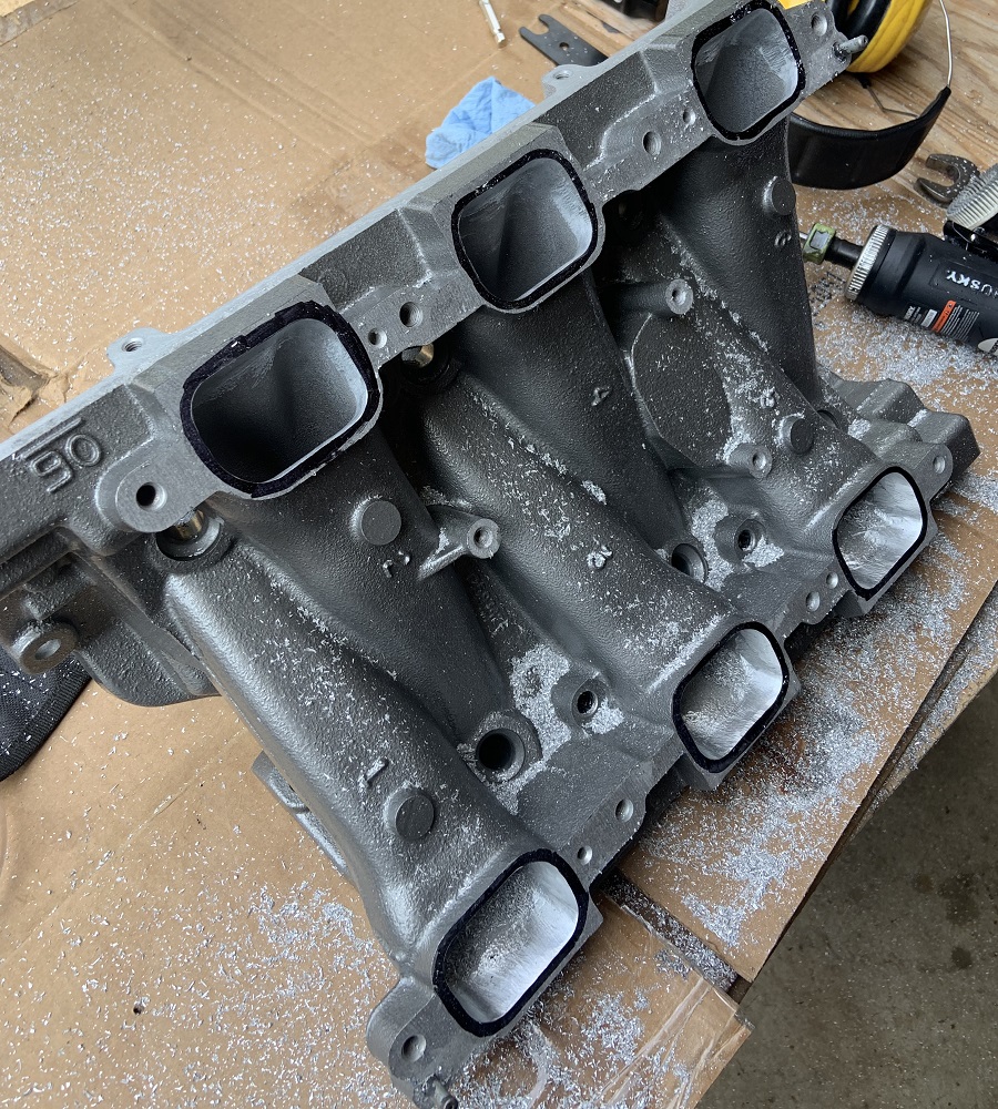
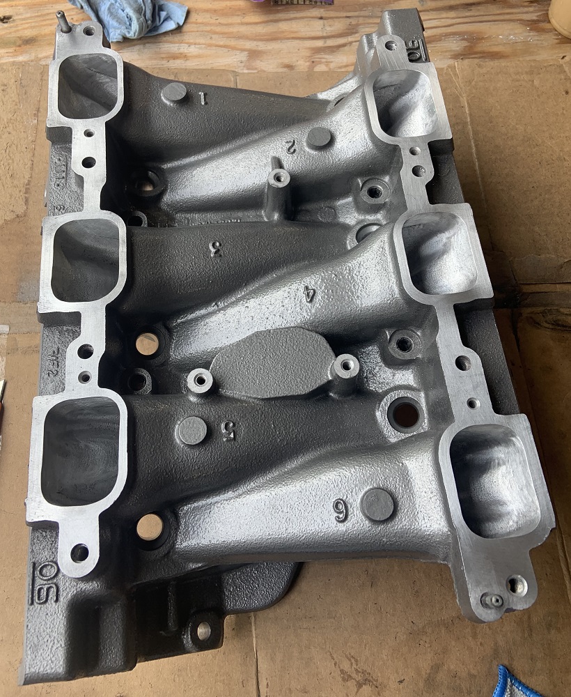
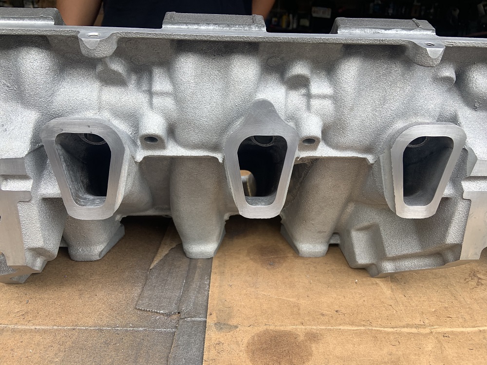
I wanted to create a velocity stack effect between the UIM and LIM, essentially open up the entrance to the port so that they can pull in as much air as the runner can flow. The runner size has been left stock.
Started to open up the UIM to LIM ports, I scribed a line into surface that was offset about 1mm from the inner edge of the UIM gasket to give it room to expand when it compresses. I used a carbide bit to open the ports up to size.
Blended the ports into the tracts a few inches with some sanding drums, and cleaned up the LIM ports that go into the head, they had very sharp jagged edges so I smoothed them out a bit
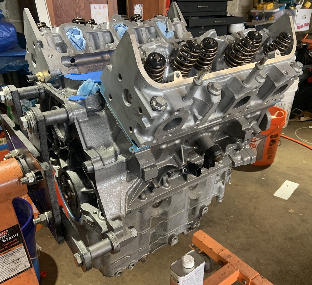
Installed the new lifters that I had previously disassembled and cleaned with the ultrasonic parts cleaner with simple green. They have been soaking in oil for weeks.
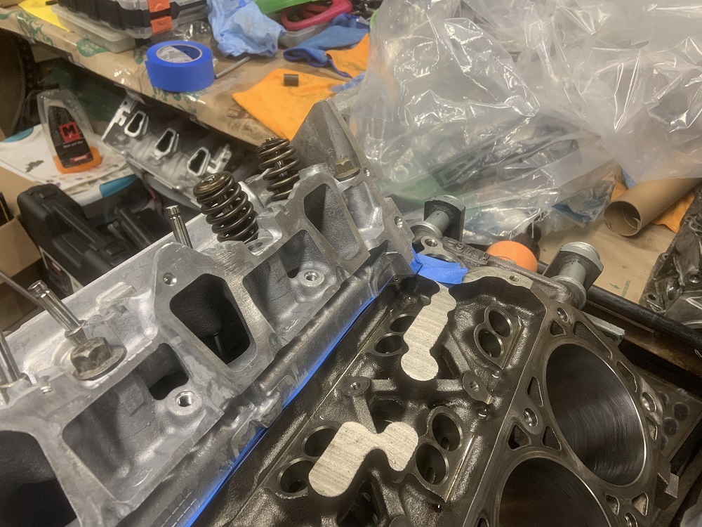
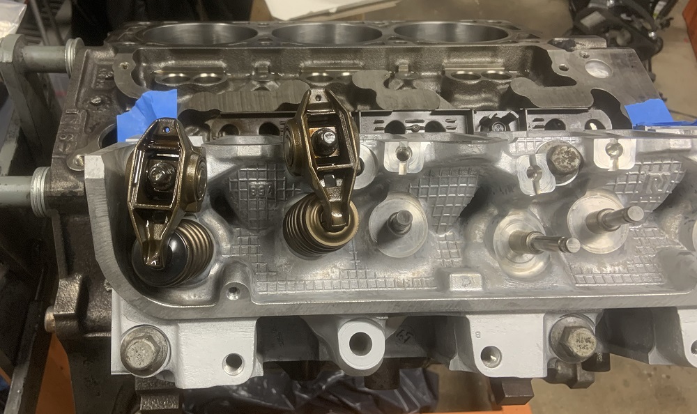
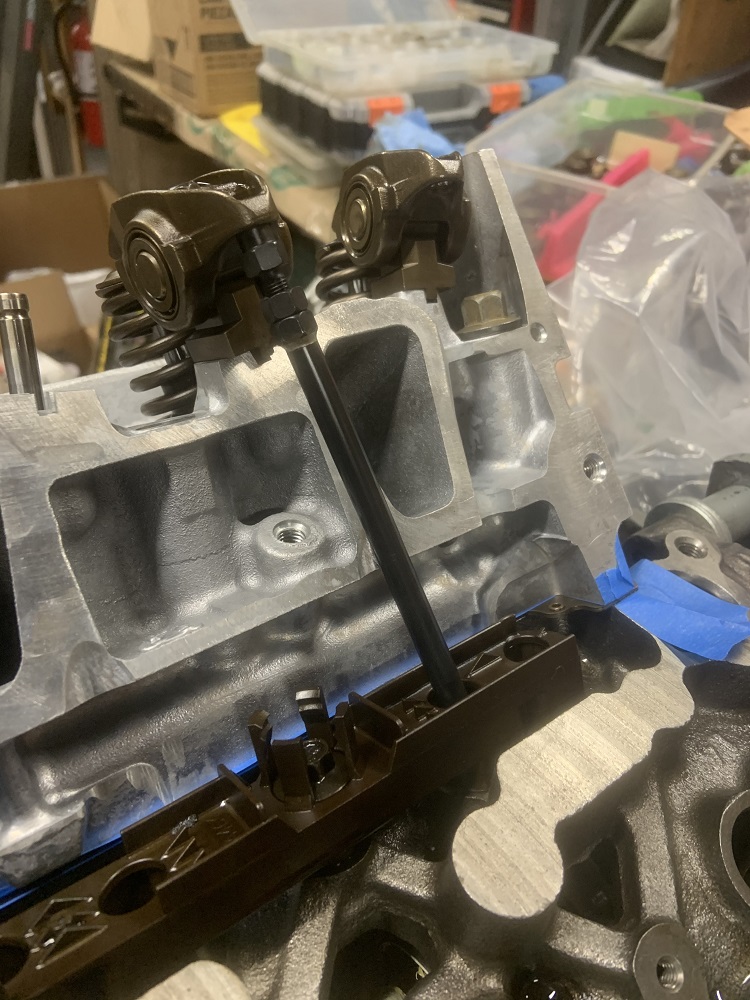
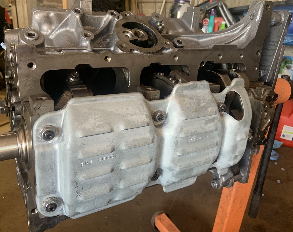
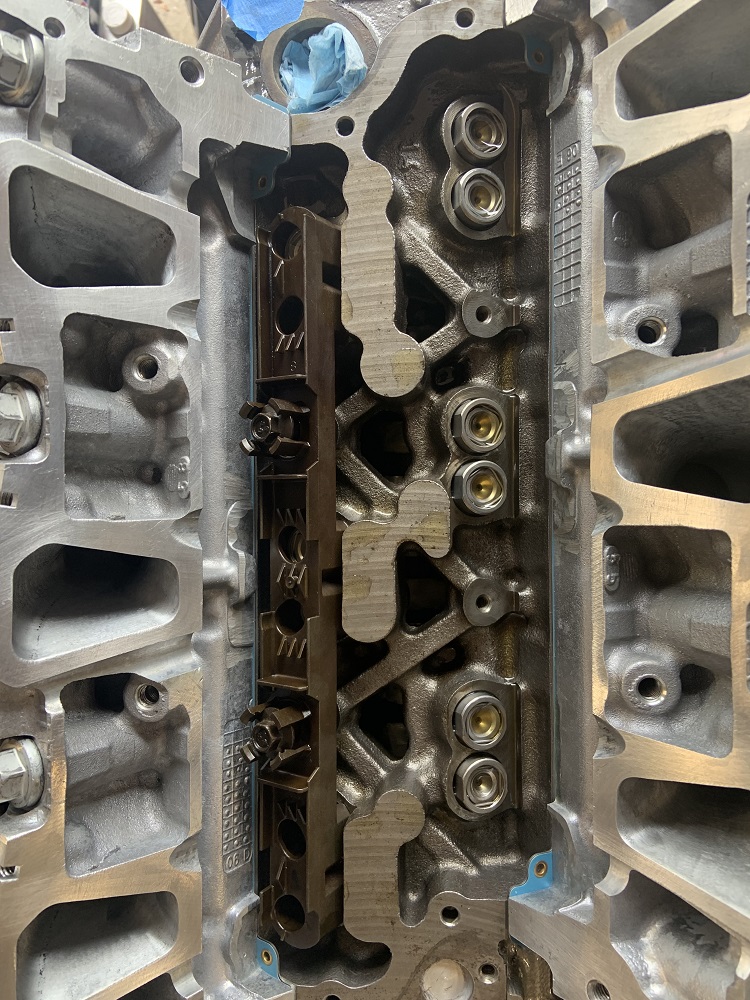
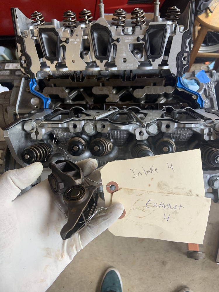
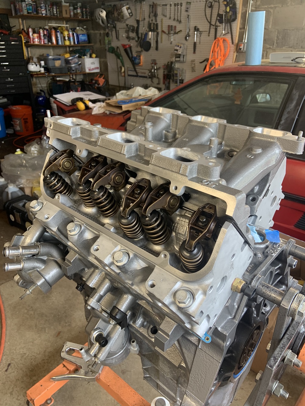
Installed the gaskets for the LIM after cleaning all surfaces with acetone several times with a white microfiber towel. Installing the new longer pushrods and the cryo treated rocker arms. I put all the rocker arms back in their original spots since they have a hardened wear spot in the correct spot for the position they have lived in all these years.
Installed everything and put the LIM in place, I want to install the injectors and fuel rails before installing the intake so I can see where the injectors end up and decide if I want to make spacers for the fuel rails.
The pushrods still spin by hand when installed fully. There is no slack but I am not sure if there is enough preload either. Could be that the lifters are not pumped up so they are collapsing easier than they normally would. The pushrods all measured out properly so I think it is fine.
Once the LIM is installed fully and I put on some of the auxiliary components like starter, flywheel, clutch, coolant crossover, and thermostat and hoses going to the oil cooler/heater, then I can pull the cradle out and get the engine mounted. I will install the motor and cradle in the engine bay so I can figure out my fuel routing, coolant routing, alternator, wiring, and exhaust. I may end up installing stock exhaust manifolds temporarily if I run out of time to fabricate headers before fall. I still have to figure out brakes, I may try and locate Seville rear calipers to deal with my handbrake issues instead of fabricating a solution for spot calipers. The Seville calipers may prove problematic to locate. I will then remove the engine and cradle assembly to make the alternator solution as well as do the routing installs of everything. Still have to pull the gas tank too.
And to think I planned on barely pulling the engine apart hah.
[This message has been edited by zkhennings (edited 07-12-2021).]
good progress I like the idea of using a light to alert you of the knock, I have a scan gauge and it's not exactly easy to glance down and find if it's knocking.. a light would come up in your periphery
Thanks, yea I thought that having a dedicated knock indicator would be really useful as it can immediately let you know that important systems have failed before any damage occurs.
I will also have an oil level light as the LZ9 comes with an oil level sensor, I may run that into the Microsquirt and have it automatically put the car into a limp mode. I bought a harness connector for the sensor and I want to have it hooked up to an LED on the dash as I think it is a far more useful parameter to monitor than the oil pressure, as it is far too late to save the motor once oil pressure has been lost on the gauge.
I will still monitor oil pressure as it is also a critical parameter, but the oil level should be more effective at helping prevent oil starvation in a hard corner for example.
Hoping to get the fuel rail and injectors test fitted and then mount the LIM today, as well as get the odds and ends assembled and have the motor ready to drop onto the cradle. In an ideal world I pull the cradle out of the Fiero today.
[This message has been edited by zkhennings (edited 07-13-2021).]