i have always wanted to run one of those noisy gear drives in many 350's i have built but have been told the same thing by MANY builders. DONT USE THEM ON A STREET MOTOR..they say like someone already mentioned that it transmits unwanted harmonics into the valvetrain so i have always opted not to do it. I hope it works for him and i hope it sounds awesome!! and if there isnt anything to that theory,then why do most people favor a belt drive?? i have been told that insulates alot of the harmonics..along with a super expensive damper too. at any rate, i really hope it works and sounds good! would love to hear an audio clip of it running when its finished!!!!
I really don't know the merits of a gear drive for the cam, however, the biker in me always prefers chain, with one exception. I had a Honda Shadow that was a shafty and it was smooooooth. I think the noise from the gears will be largely dependent on the quality of the cut on the gear teeth. The finish and smoothness of contact are really critical so far as I know. So, the quality of the kit is really the question for smoothness IMHO.
When I did my first porting job I posted it as a learning experience I could share with all the guys also doing it for the first time. when I look at this bowl work my hat goes off. That is really sweet. Way to go
Arn
IP: Logged
05:17 PM
GTFiero1 Member
Posts: 6508 From: Camden County NJ Registered: Sep 2001
I was just syaing the studs would be a worth-while investment and a little insurance for the higher rpm, a set of 3/8th studs is about 20 bucks, then they just need to be drilled/tapped. Ive seen them pull out on people, but then as long as the spring pressure isnt too much different than stock you can get away with stock press-ins.
A gear drive is accurate yes but as mentioned not too many people use them for a reason. A quality (ie not no-name/stock/tiawann) double roller chain set will be just as accurate. Ive always used chains and same with my buddies that run 8 second 8000rpm small blocks. Really theoretically all the noise you hear from them transfers to harmonics that are then induced into the motor through the cam and valvetrain. theres no harmonic damper on the end of a cam like on the crank. Im not saying after 10K miles the motor is gonna exoplode or anything, and ive known people that have them and had no problems, just wouldnt recommend one to someone except maybe for a straight up drag car where motor longevity isnt a main priority. Actually a belt drive is the best as far as cam timing accuracy and the belt helps absorb harmonics, but a $800 belt drive is hardly necessary in a street motor. You have the gear drive and installed already, use it, im sure you wont have any problems, just food for future thought.
The 305 isnt that much of high rpm performer for a few reasons. Heck factory redline on them was about 5K. Though less reciprocating weight, the bore and stroke hurts it a bit. Long stroke, small bore. With a longer stroke to smaller bore the piston has a farther distance it has to travel in a given rpm than a big bore/short stroke motor. So a big bore/short stroke motor has the ability to rev higher because the piston speed is lower at the same given rpm as a small bore/long stroke combo. Also a longer stroke gives greater mechanical advantage on the crank, making more torque. Shortening the stroke will decrease mechanical advantage, increasing the rpm necessary to make the same power. This more or less offsets the reciprocating weight advantage a 305 has due to its small bore. This is why chevy made they're 302 for trans/am racing- big bore/short stoke, high rpm power. Same why people de-stroke 400's to 377s, big bore/short stroke. People have even de-stroked LT1's using the L99 4.3 crank netting that bore/stroke combo for higher rpm power (LT1s with L99 cranks produce 302ci) Also lightweight pistons and cranks are available to help make the big bore motors reciprocating assembly weigh less, though technically the shorter throws of the crank help with over-all weight also.
The 305s small bore also gives into valve shrouding by the bore which will impede on upper rpm flow ability. I think actually using heads with smaller 1.94/1.50 valves would be an advantage here compared to using 2.02/1.60 valves. Though the larger valves have the ability to greater flow, the smaller valves should flow plenty for a 305 and help in the upper rpm due to the less shrouding by the bore. So the heads should be pretty decent for this motor when your done. I know they're still a work in progress but with the pictures of the heads, id work a little more on the plateu/flat area around where the valve stem goes through, try to get it more to a tear drop shape minimizing the flat area as much as possible. i do realize its hard to get close with that though without potentially hitting the guides.
Now this is all just food for thought info, suggestions, etc Im not saying your doing anything wrong or bad in anyway what so ever. I want to see how this turns out really as i am a die-hard chevy guy no matter what engine it is. Ive built 350s, 383s, 400s etc. Ive ported heads, I am NHRA licensed to 7.50et, ASE certified tech, UTI/Hot-Rod U and Ford FACT graduate and a repair/performance shop owner.
IP: Logged
05:37 PM
tjm4fun Member
Posts: 3781 From: Long Island, NY USA Registered: Feb 2006
um just a note on the gear drive. My starboard engine, the counter rotating 350 is a gear drive cam. only differrence is no idler assembly, as the cam rotates in the normal way. the motor is a 1975. it has around 1400++ hours on it. normal cruise speed is 3150 rpm. it makes no noise compared to the other side which is a chain drive. by comparison, you would need to run your car at a track to put the load on the motor that a marine engine goes thru in normal use. (cars average about 30% of engine power used in normal driving, vs marine at 80% of engine power.)
IP: Logged
06:04 PM
Will Member
Posts: 14303 From: Where you least expect me Registered: Jun 2000
Originally posted by GTFiero1: With a longer stroke to smaller bore the piston has a farther distance it has to travel in a given rpm than a big bore/short stroke motor. So a big bore/short stroke motor has the ability to rev higher because the piston speed is lower at the same given rpm as a small bore/long stroke combo.
It's got the same stroke, and therefore same piston speeds, as a 350...
It's still a 5 litre V8... if you can get it to breathe, it will make power. It's still oversquare. A 4.9 is square and the reason it doesn't make any power is just breathing.
IP: Logged
08:53 PM
prostreet505 Member
Posts: 426 From: Wind Lake, WI 53185 Registered: May 2007
I think this head/intake/cam/carb package will be less than $2000
That is a great article. Which brings up the point to this build. You can pick up a decent 305 for cheap if not free and make it perform just as good if not better than a 350 with a cheaper price tag. Junkyards raise the prices on what is in demand. What does everybody want a 305 or a 350?
Craig
IP: Logged
09:44 PM
prostreet505 Member
Posts: 426 From: Wind Lake, WI 53185 Registered: May 2007
I really don't know the merits of a gear drive for the cam, however, the biker in me always prefers chain, with one exception. I had a Honda Shadow that was a shafty and it was smooooooth. I think the noise from the gears will be largely dependent on the quality of the cut on the gear teeth. The finish and smoothness of contact are really critical so far as I know. So, the quality of the kit is really the question for smoothness IMHO.
Arn
You are right about the quality of the cut. They make differant cuts of gear drives depending on what noise level you want. They make a quiet version and a version machined for noise, which I have chosen for this build. Why did I choose the noisy version? I am old school, thats the only reason why I chose the noisy version. Thanks for the compliment on the heads.
Craig
IP: Logged
10:02 PM
prostreet505 Member
Posts: 426 From: Wind Lake, WI 53185 Registered: May 2007
Now this is all just food for thought info, suggestions, etc Im not saying your doing anything wrong or bad in anyway what so ever. I want to see how this turns out really as i am a die-hard chevy guy no matter what engine it is. Ive built 350s, 383s, 400s etc. Ive ported heads, I am NHRA licensed to 7.50et, ASE certified tech, UTI/Hot-Rod U and Ford FACT graduate and a repair/performance shop owner.
I came across a bit strong on my reply to you, and I apologize for this. Its just my email has been flooded with smart a** comments from people about how I am wasting the forum members time on this build and how I am misleading everybody into thinking this is going to be an economical build when in reality it is not. It just URKS me that they cannot post there candy a** replies here so everybody will know how big of fu** offs they really are. And they know who they are!!!
I understand what you are saying and I appreciate the feedback. Keep in mind though I want to do this build in a way you can do this at your home. I also am a 3rd generation shop owner that has the facilities to do this build in a manner that would be out of reach of most people. I want to keep it as simple as possible but be able to have great gains for the money. The scew in studs would be recommended but, I think drilling and tapping the heads would be to advanced for some people, not to mention the price of a good tap & die set. At the end of the build there is going to be a breakdown of all the parts and material needed to do this build along with the specialty tools required which all falls into the $2000.00 budget. Which is why I am not going to go crazy on the port and polishing and stay away from the areas that could get you into trouble. I hope this sheds some light on the reasoning behind why some things are not being addressed. Once again, I apologize for my rudeness towards you in my last reply.
Craig
IP: Logged
10:44 PM
prostreet505 Member
Posts: 426 From: Wind Lake, WI 53185 Registered: May 2007
My dad has one of the last 400 crate engines ever built installed in a '75 Jaguar and currently running under a TPI intake manifold. He installed a double roller timing chain when the engine was brand new. It now has over 300,000 miles on it and will burn the tires in the Jag as long as you hold your foot down...
I'm not convinced that there's anything wrong with a timing chain that compromises its durability for a streetable engine. Its accuracy is defined by stretch, which will be minimal with near stock valve spring loads.
IOW, I think that the gear drive is overkill and that the increased noise will be a compromise that is not offset by measurably better performance.
That type of gear drive tries to pull the right bank gear through the mesh between the crank and cam gears. This puts more lateral loading on the cam snout than you might think. Is it as much as a chain? Who knows? The torque transmitted is the same either way.
I think the best type of gear drive is one with a single fixed idler, but one of those would be out of budget for this build...
Don't get me wrong I am not saying your true double roller chains are junk, because they are not. They are very dependable and quite strong. It all falls down to personal preference. I choose the gear drive because I have had great results with them in the past.
Craig
IP: Logged
10:58 PM
3084me Member
Posts: 1035 From: Bucks County, PA Registered: Apr 2005
My current 310cid 305 is doing well. I just test fired it. The P.J. noisy gear drive is a bit quieter than my BBC's but I am running open headers so it is a bit drowned out.
PS. I always machine the block, (it's much softer than the shaft of the gear drive). A round stone works great. I don't think I've ever heard of someone modifying the shaft of the idler before. Personal preference I guess.
My take on the gear drive "debate" for those who have commented (if anyone cares):
I've had a few cars in the 9sec 1/4 mile E.T. range ( ok 9.29 but doesn't 9 sec sound better???) and the only reason I "refrained" from using the gear drive at that point was to switch to an external belt drive (dry system) that was simple to adjust without taking anything apart. Most of the other guys in that ET range and below pretty much did the same thing. Not that a gear drive wouldn't be fine, just easier to externally adjust the belt drive between passes. You can adjust the cam timing infinitely between straight up and 6 degrees - and sometimes more with the belt drive on many systems and this is a huge help on the faster running cars.
Although the gear drive does transmit added harmonics as stated, Who really cares (when it comes to a bracket car), We rebuild the engine at the end of the season (or sooner if needed / or destroyed) so it's really of no concern if someone really wanted the noise. Where we/I would never reuse a gear drive (the same way nobody would reuse a chain), the belt drive is more cost effective in that a belt replacement is usually all you need. The belt takes most of the abuse making it a better option (again... for most) in the long run..
The second reason that many bracket car racers / builders don't use them (not me) is the ability to run a belt drive external oil pump off of the external belt drive / timing belt and do away with the internal pump and the added HP drain at higher RPMs
Great work so far, keep us posted.
Ps. prostreet505.... Is it my monitor or the angle of the shot or do your cross-hatches look a bit "steep" ???.
------------------ I'm not driving too fast, . . . I'm flying too low.
[This message has been edited by 3084me (edited 12-19-2007).]
IP: Logged
11:52 PM
PFF
System Bot
Dec 19th, 2007
Will Member
Posts: 14303 From: Where you least expect me Registered: Jun 2000
Actually, 9.29 sounds better, because "9's" could be 9.99...
I hear ya'. I guess it's all in how you say "9 second car". I'm an optimist so I think 9.01
(I've also wanted to be able to say "in the 8's" but since I no longer have a box full of cash under the bed, I guess then may not happen anytime soon... I'm getting old, my back hurts etc.. I guess pretty soon, I can just sit on the porch and say 'Why do those dang kids have to make those cars so loud"... Then I can eat dinner at 3:30 and go to bed by 7:00. - Ahhhhhh the good old days....
------------------ I'm not driving too fast, . . . I'm flying too low.
[This message has been edited by 3084me (edited 12-19-2007).]
IP: Logged
04:00 PM
prostreet505 Member
Posts: 426 From: Wind Lake, WI 53185 Registered: May 2007
My current 310cid 305 is doing well. I just test fired it. The P.J. noisy gear drive is a bit quieter than my BBC's but I am running open headers so it is a bit drowned out.
Is it my monitor or the angle of the shot or do your cross-hatches look a bit "steep" ???.
Congrats on your 305 You should be happy with it. I've also noticed that the noisy version of the Pete Jackson gear drive is not as noisy as other brands, but once the exhaust is muffled some you will be able to hear it more. Good Eye on the cross hatch. It is steeper than normal, but there is a reason behind that which will be addressed later on in the thread. But once again good eye. I am amazed that only one person has caught this.
Craig
IP: Logged
10:57 PM
Dec 20th, 2007
3084me Member
Posts: 1035 From: Bucks County, PA Registered: Apr 2005
It's weird. I've been a bit busy and haven't been on the board / following the thread so after I posted my comment about the crosshatch, I figured : "Someone had to have mentioned that before now..." The more I looked, I didn't see any comment so I thought I'd toss one out there. Kind of hard to tell crosshatch angle due to the flash and angle of camera in many cases but I thought one or 2 shots appeared to be pretty "steep". (I tend to leave mine a little on the steeper side) but I do have to admit, I did have some scoring/excessive heating in a few cylinders in one B.B. Olds engine a number of years ago when I went too steep.
I'm a little more conservative on this engine and went a bit smaller than the previous cam we had in it which just hit the 300HP mark. With the corvette rams horns instead of the long tube headers that were on the Monte SS the engine was in, slightly smaller cam and "full" (if you could call it that on a Fiero Replica) exhaust, I'm shooting for 265-280HP on this one. and should pretty much hit that without being too much lower. If I fall a bit short, I could always use my Sanderson CC-90's but I really don't want to mess around with headers on this project. The 2.25" rams horns should do ok for me and keep the engine area a bit cooler in the process.
Keep up the good work.
Ps. I also went with a 2pc timing cover just on the off chance the gear drive got annoying while screaming behind my passenger's head and I decided to replace it (or play with cam timing).
------------------ I'm not driving too fast, . . . I'm flying too low.
[This message has been edited by 3084me (edited 12-20-2007).]
IP: Logged
12:15 AM
Jan 3rd, 2008
DPWood Member
Posts: 540 From: Aylmer, Ont. Canada Registered: May 2002
I agree with Arn.... Those ports look sweet. I'm just hoping my first foray into doing the bowl side doesn't result in having to re-do valve seats.
I do have another question for ya...
Over X-mas holidays I tore down the short block of my 305 and started prepping it. Part of what I normally do is open up the four main oil drainback holes as much as possible with a carbide burr and blend it in with flap wheels to get a smooth transition. I was wondering if it be OK to tap the small holes in the lifter valley and install some pipe nipples to limit the amount of oil dropping down on the crank and reduce windage losses?? I'll also be going through the oil pump one of these nights while I'm at work. I usually shim the relief spring to increase pressure through the mains/crank. My concern would be that the rods are lubricated, in part, by that oil dropping down. Would the increase of oil pressure through the bearings be sufficient??
Thanks
David
IP: Logged
09:41 AM
prostreet505 Member
Posts: 426 From: Wind Lake, WI 53185 Registered: May 2007
I was wondering if it be OK to tap the small holes in the lifter valley and install some pipe nipples to limit the amount of oil dropping down on the crank and reduce windage losses??
Thanks
David
I personally would not recommend doing that. You want your oil to get back to the pan as quickly as possible without starving your upper half from oil. Plus you don't want to start puddling the oil in the lifter valley. If you are going to use this engine as a driver then you will not notice any gains by restricting the oil dropping down on the crank. I would try and get the oil back to the pan quicker.
Craig
IP: Logged
10:20 PM
prostreet505 Member
Posts: 426 From: Wind Lake, WI 53185 Registered: May 2007
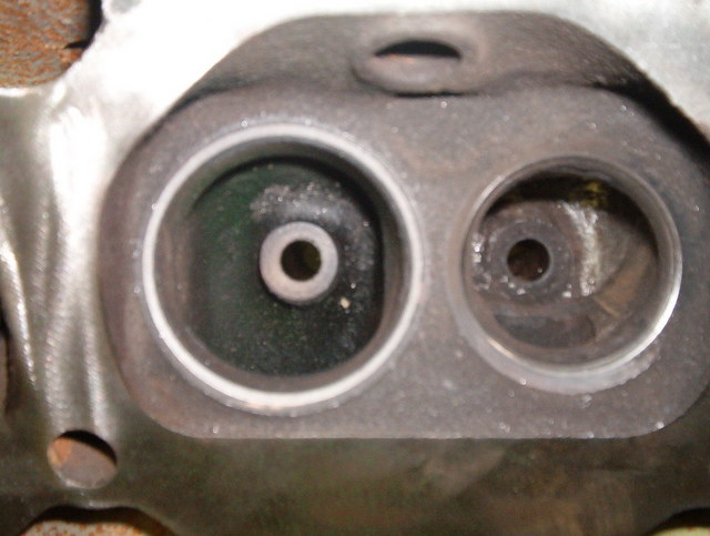
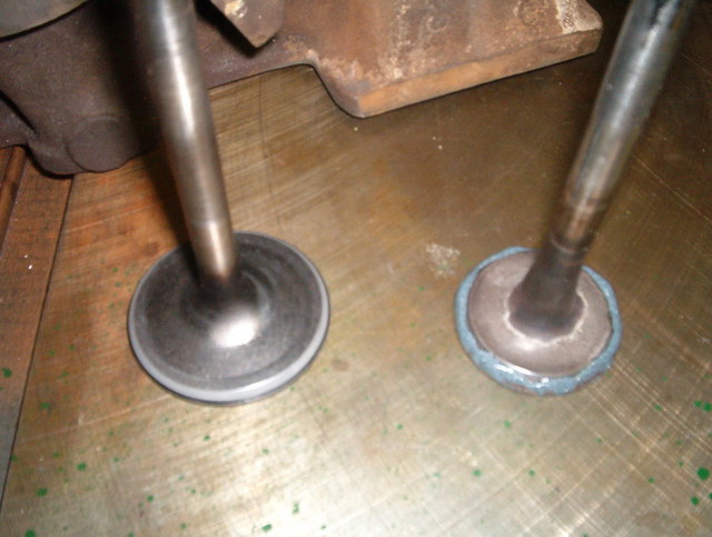
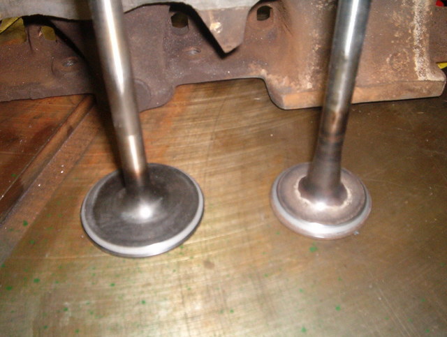
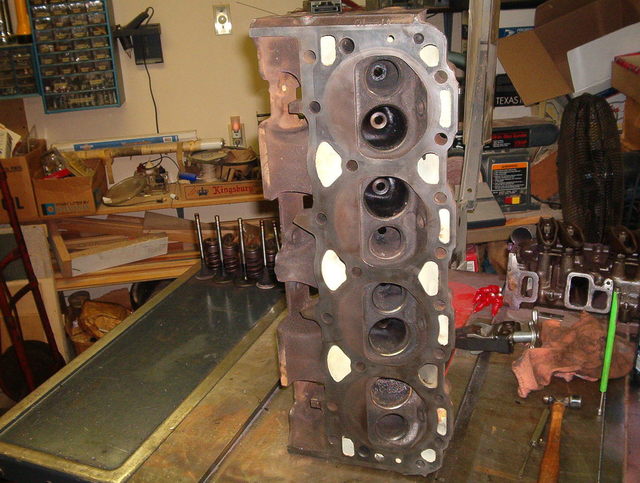
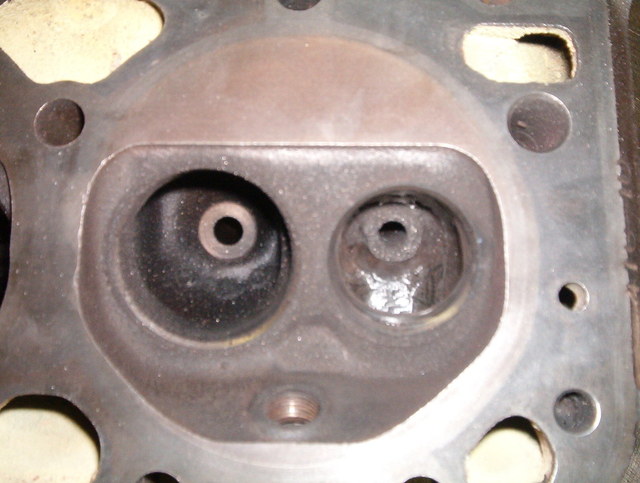
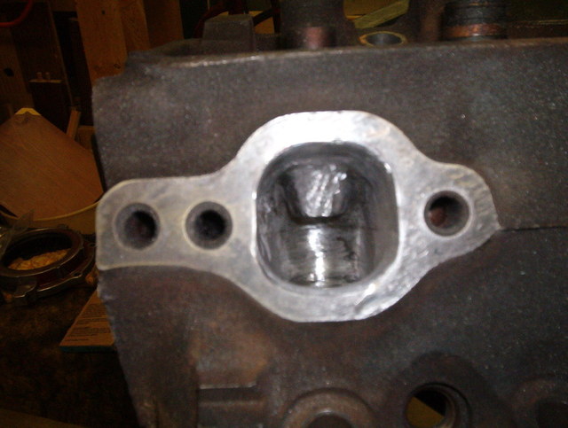
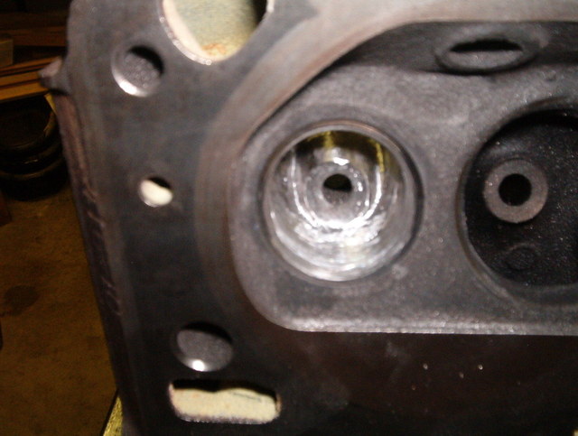
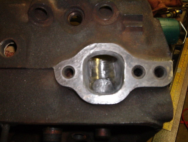
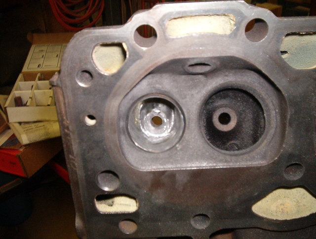
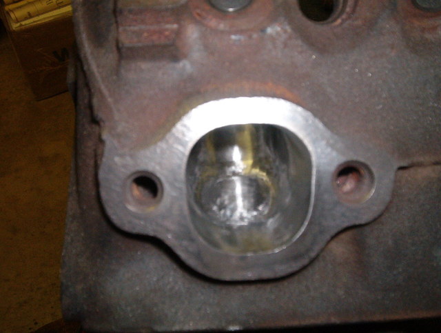
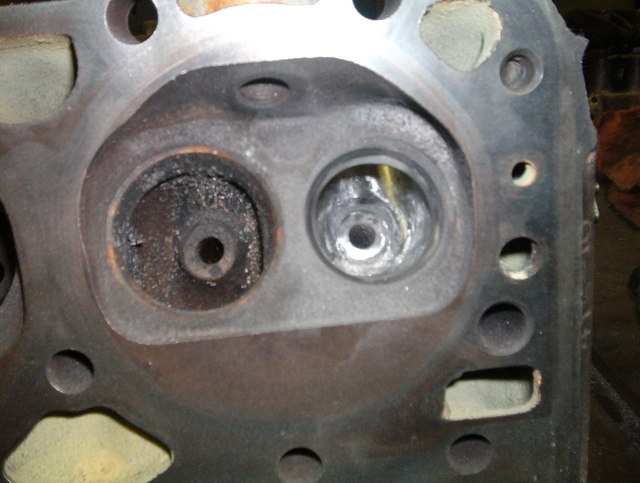
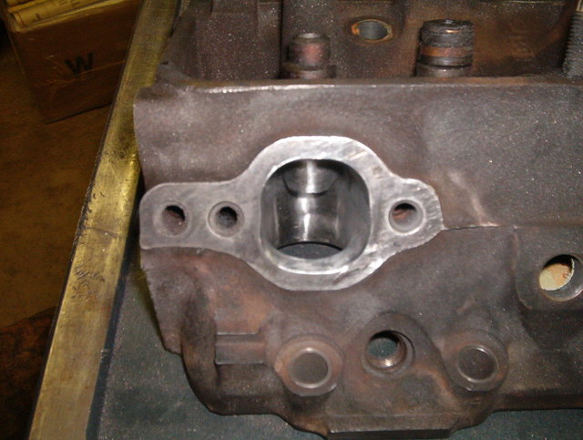
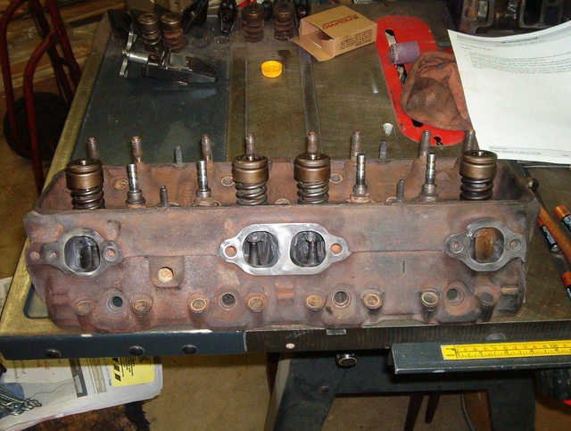
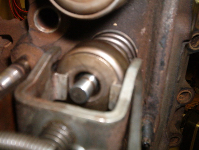
Now that the Holidays are over I can get back to work on my projects. I am going to start the valve seating process. Since we are not taking the heads in to have the valves and the seats redone, we are going to make sure that the valves will seat properly and have a good seal. This is what the heads and valves look like prior to the valve seating process:
You can go to your auto parts store and buy a tube of valve grinding compound. This is what I am using for this process.
We are going to start with the intake valve. You want to start out by applying some of the compound to the seat of the valve:
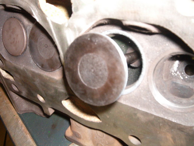
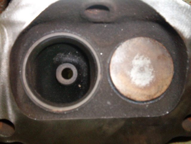
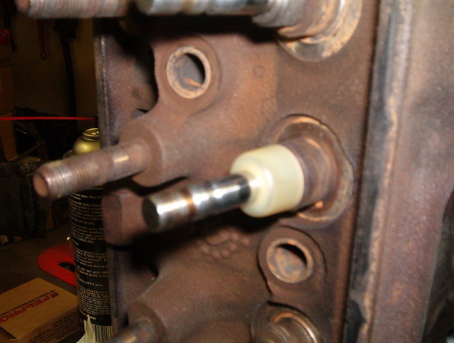
Then you want to slide the valve back into the head and spin the valve in the head while applying pressure to the valve face. Work the valve back and forth in a twisting motion for about 1 minute:
Then you want to slide the valve out of the head a little bit and spin it 180 degrees and repeat the process about 3 times:
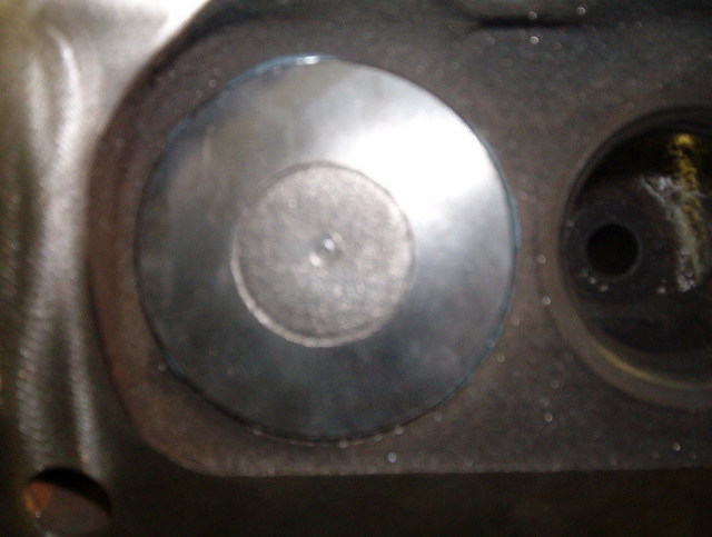
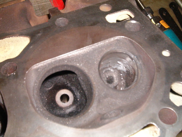
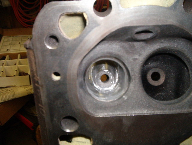
When done wipe off any excess compound off the valve and the head and they should look nice and smooth and be free of any pits that were there previously. This is what the head and valve should look like when done:
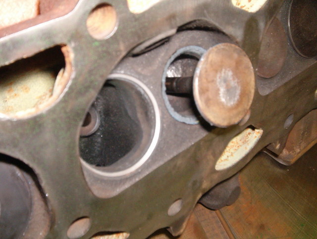
Now do the same to the exhaust valve. Start off by applying the compound to the valve:
Then insert the valve into the head and twist the valve back and forth while applying pressure to the face of the valve:
Then slide the valve out of the head a little and rotate the valve 180 degrees and repeat the process about 3 times:
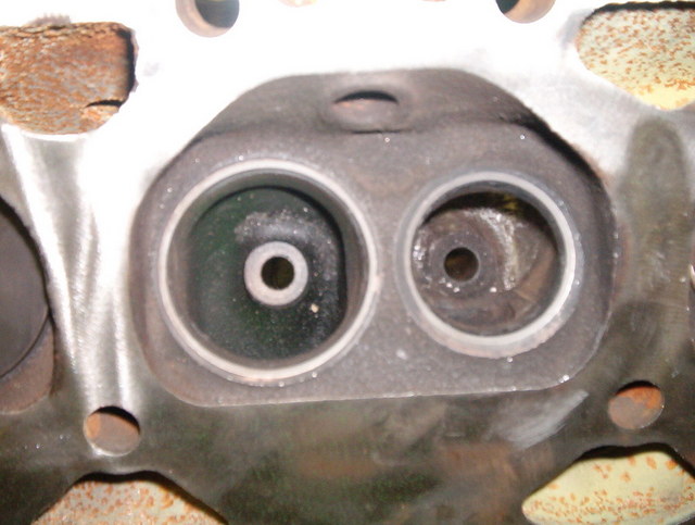
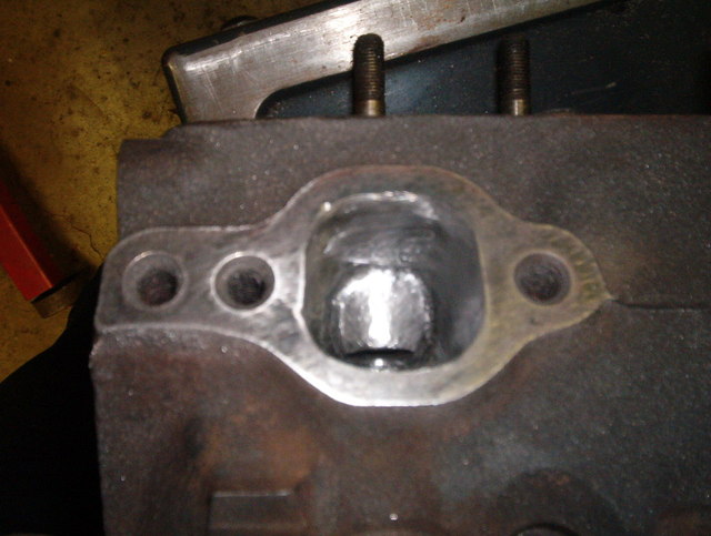
Then wipe off the excess compound and the heads and valves should be free of any pits and should be nice and smooth where the compound was:
Repeat this process for all the valves and you are sure to have a nice seal on the valves.
The next step is going to be the polishing of the ports, which is what everybody has been waiting for. I will get to that this weekend.
More to come......
Craig
IP: Logged
11:14 PM
Jan 4th, 2008
Will Member
Posts: 14303 From: Where you least expect me Registered: Jun 2000
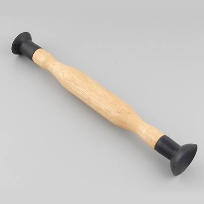
Show your audience a pic of the valve grinding tool...
I did not grind the valves so there is no tool to show. I reseated the valves in the head using valve grinding compound. The only thing I used was the valve grinding compound and my hands to twist the valve left to right.
Craig
IP: Logged
08:57 PM
KaijuSenso Member
Posts: 911 From: Westland, MI Registered: Jan 2007
please keep the good information rolling in! I'm glad somebody decided to try to prove a point with these engines. It's more fun to do something unique. -Thumbs up!
IP: Logged
11:16 PM
PFF
System Bot
Jan 5th, 2008
Will Member
Posts: 14303 From: Where you least expect me Registered: Jun 2000
Originally posted by prostreet505: I did not grind the valves so there is no tool to show. I reseated the valves in the head using valve grinding compound. The only thing I used was the valve grinding compound and my hands to twist the valve left to right.
Craig
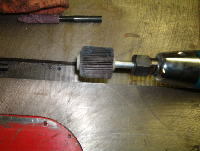
Ahh... You used valve grinding compound, right? Sounds like you ground the valves to me... As far as the tool goes, I was referring to one of these:
IP: Logged
08:47 AM
prostreet505 Member
Posts: 426 From: Wind Lake, WI 53185 Registered: May 2007
Ahh... You used valve grinding compound, right? Sounds like you ground the valves to me... As far as the tool goes, I was referring to one of these:
I did not spend the extra $20.00 for that tool, because you can get the same results by using your hands. That tool might make it a tad bit easier and save you a couple of minutes, but I would rather use that money later in the build. Not to be rude and don't take this as I am attacking your comment but, just because I used valve grinding compound does not mean I ground the valves. If I was grinding the valves I would of used a machine that would have ground the valves or used some type of stone like this one.
The procedure that I have done is called reseating the valves. If you take your heads to a machine shop and ask them to grind the valves, they will do a totally different procedure.
Craig
IP: Logged
09:54 AM
tesmith66 Member
Posts: 7355 From: Jerseyville, IL Registered: Sep 2001
To be more specific- you lapped the valves. This can also be done by turning the valve with a drill (attached to the stem at the top after it is inserted into the head) and pulling the valve against the seat.
Lookin' good!
------------------ 1986 SE 350 V8
IP: Logged
10:09 AM
Will Member
Posts: 14303 From: Where you least expect me Registered: Jun 2000
Potatoe/Potahto. We could debate terminology all day and not get anywhere.
I posted that pic to show people something that they could use to make the job a little easier.
Stick to your vegetables. In engine work, valve grinding and valve lapping are 2 totally different processes & should only interchanged by those who are either incompetent or confused.
IP: Logged
07:41 PM
Will Member
Posts: 14303 From: Where you least expect me Registered: Jun 2000
Valve SEATS are ground with the drill driven grinding stone tool that locates in the valve guide as described above.
Valves themselves are CUT, not ground, on a device resembling a lathe. If you asked a machine shop to grind valves, they might look at you funny.
Or the valve and the seat can be lapped/ground/seated/whatever together as a pair as the thread author has done, either by hand, with a suction cup tool, or with a drill as someone else mentioned.
Is the horse dead yet? Keep beating!
IP: Logged
09:14 PM
tjm4fun Member
Posts: 3781 From: Long Island, NY USA Registered: Feb 2006
Now that was not nice. any machine shop in the NY area will not look twice if you say valve grind. in fact, they are usually cut with a grinding wheel on a lathe like valve grinding machine, a much more precise method than "cutting" them, which afaik is not done anymore. they are all ground.
the procedure shown here is lapping the valves in. in reality, it will result in the best seal for valve to seat, and will lead to more of a measurable performance increase per $ than a 3 or 5 angle valve job, and almost always longer lasting. it can be done with the suction cup tool or a drill, and even a first timer can get a good seal. Now let's be nice, there is alot of effort being put into an article like this for the new builder to learn from.
[This message has been edited by tjm4fun (edited 01-05-2008).]
IP: Logged
09:31 PM
Will Member
Posts: 14303 From: Where you least expect me Registered: Jun 2000
Okay enough is enough. Lets try not to turn this into a flaming thread. There is enough of them around here already.
Will, I said in my last post that I was not attacking your comment. I don't know where you are located, but here in Wisconsin there is a difference between grinding the valves and lapping the valves. If you would like I can go to my shop and take a picture of a valve grinding lathe and the procedure and the results will be entirely different than what I have done. I am not questioning your intellectual skill in the automotive field, but in this case there is a difference.
The tool you pictured will make the job a bit easier, but I fiqured this is a budget build and the money could be used elsewhere. Granted the tool ranges from $5.00 to $20.00 but I got the same results without it.
Craig
IP: Logged
12:18 AM
prostreet505 Member
Posts: 426 From: Wind Lake, WI 53185 Registered: May 2007
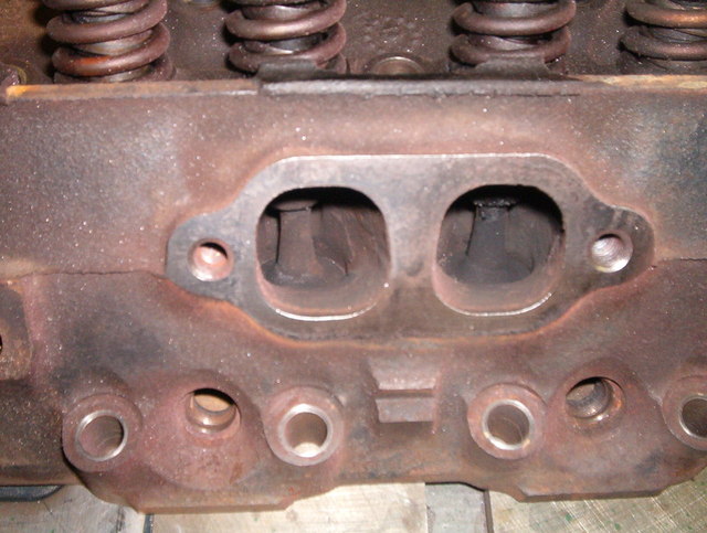
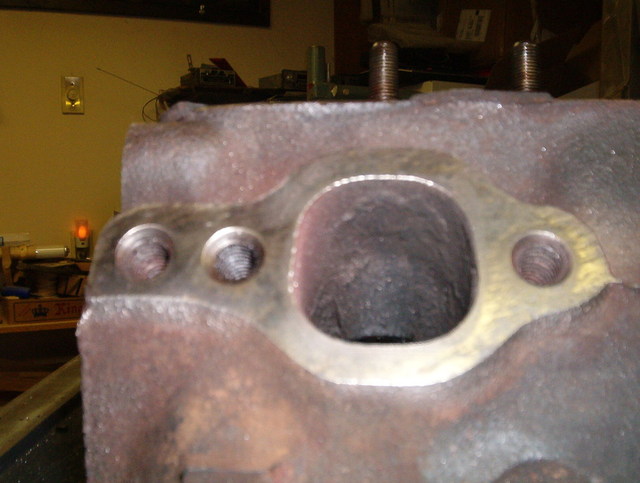
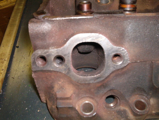
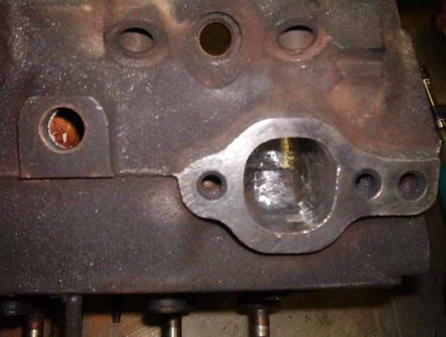
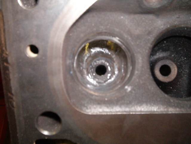
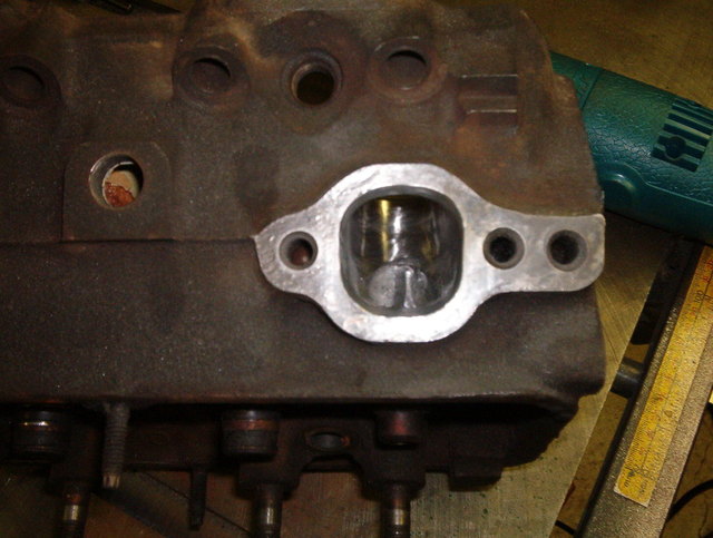
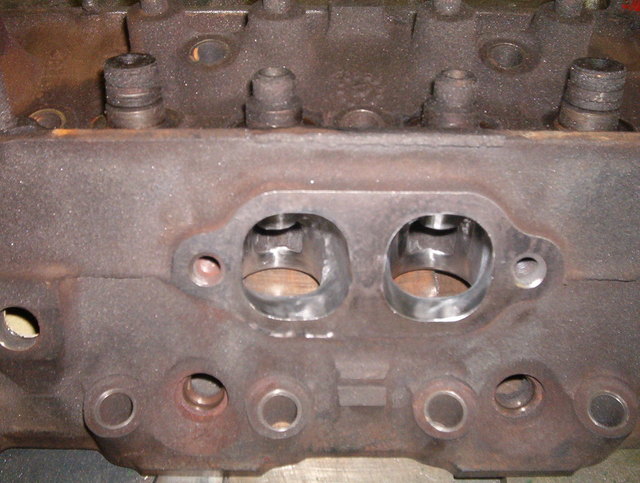
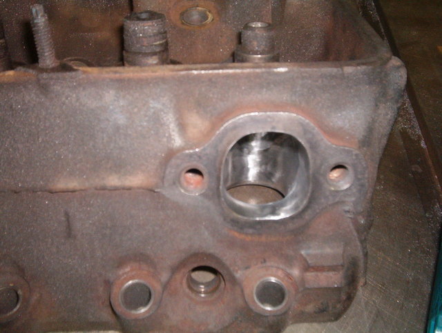
Now we are going to start the polishing of the exhaust ports. Here is what they looked like before polishing:
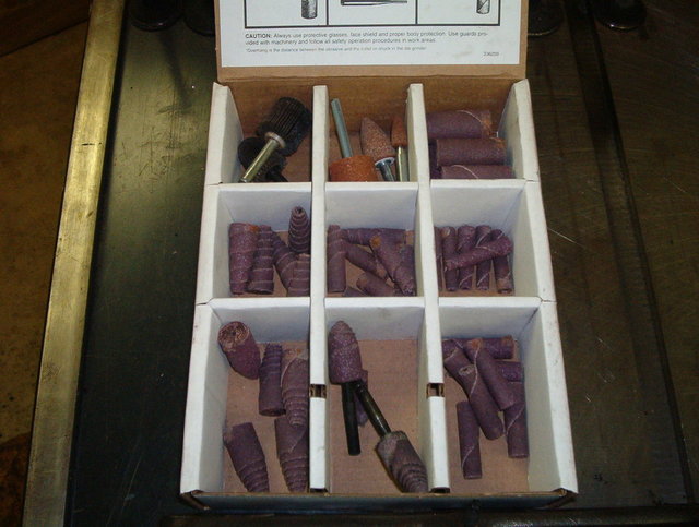
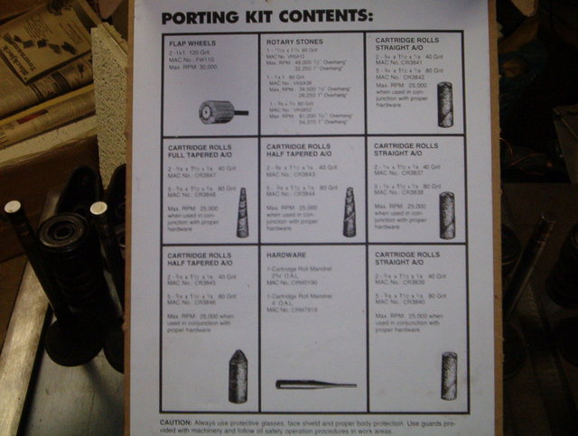
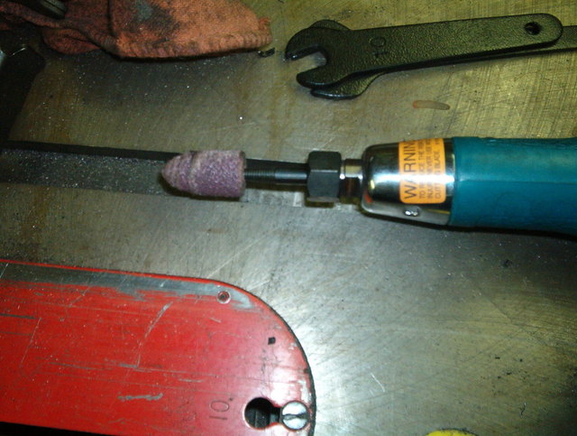
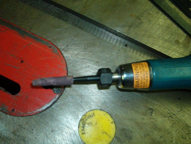
Here are the tools we are going to be using:
Cutting Bits:
Port and Polish Kit:
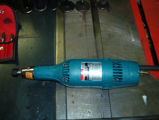
High speed rotory tool, die grinder or Dremel. You can use a drill, but it is easier if you have a rotory tool that reaches 25,000 rpm:
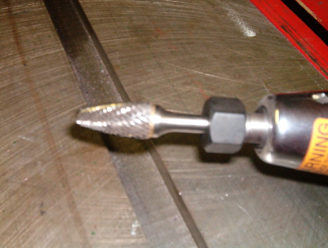
We are going to start off using the large cutting bit:
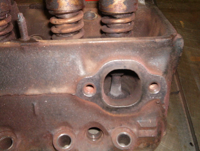
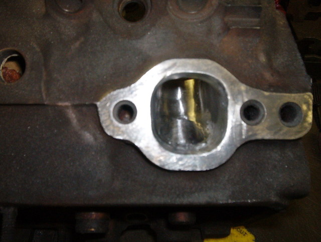
Work around the bowl and the port removing any casting imperfections, but don't get to close to the valve guide or the valve seat with this bit or it can be a costly mistake. Here is what the port and bowl should look like after you have removed the imperfections:
Now you want to switch to the long narrow bit to get the areas you could not get with the larger bit:
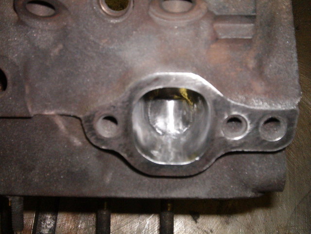
Use this bit to work closer to the valve guide to remove the imperfections, but don't worry if you can't get everything at this time. The polishing bits will remove what you can't get with this bit. This is how it should look:
Now you want to use a larger 60 grit polishing bit and a narrow 60 grit bit for the hard to get areas:
Use these bits to work around the bowl and the port to start to smooth out the marks from the cutting bit:
Now use a large 80 grit bit and a narrow 80 grit bit for the hard to get areas:
Use these bits to also work around the bowl and port to start to smooth everything out. I try and get it as smooth as I can with these bits. It makes the next step alot easier:
Now you are going to use the 120 grit flapper wheel:
Use this wheel to bring the port and bowl to a nice smooth polished finish:
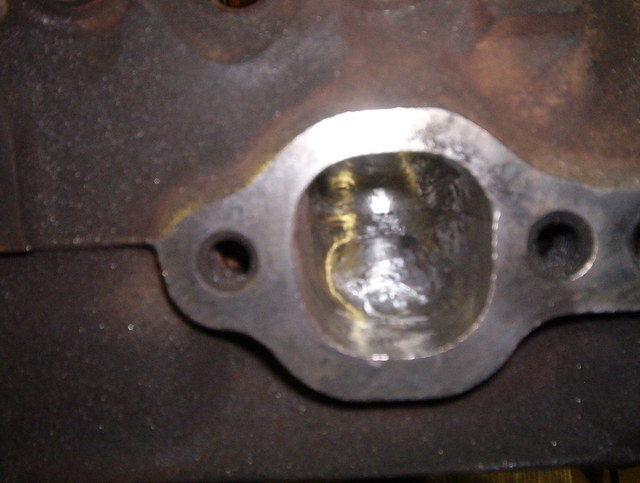
Do this same procedure to all of the exhaust ports and they should turn out looking like this:
Take your time doing this as you will get better results. This job took 1 hour per port. So it took me 4 hours to do the exhaust ports and bowls.
More to come.....
Craig
IP: Logged
11:01 PM
PFF
System Bot
355Fiero Member
Posts: 549 From: Victoria, BC Canada Registered: Dec 2004
Question. If you mentined this earlier and I missed it in the reading, my mistake.
Did you do a gasket match to open up the exhaust ports as much as you could as you were polishing them? I saw the intake gasket match you showed but am curious if you need to do the exhaust as well.
Thanks and keep up the great thread. Don
[This message has been edited by 355Fiero (edited 01-06-2008).]
IP: Logged
11:18 PM
prostreet505 Member
Posts: 426 From: Wind Lake, WI 53185 Registered: May 2007
Did you do a gasket match to open up the exhaust ports as much as you could as you were polishing them? I saw the intake gasket match you showed but am curious if you need to do the exhaust as well.
Thanks and keep up the great thread. Don
OH CRUD!!!!
I forgot to post that section. I did do a gasket match on the exhaust ports using felpro gaskets part # MS 9275 B I will update that section of the thread tomorrow. My eyes are going bonkers tonight from resizing pics.
wow Craig, i had no idea all that was involved, and the amount of time! I was thinking it was just taking a dremel and five minutes of work, but wow, i was off. And so i have to say thanks again for the porting on my engine! The porting looks so smooth in the pictures
And a little late, but Happy New Year!
And a bump for ya
IP: Logged
11:56 PM
Jan 11th, 2008
fiero go fast Member
Posts: 1728 From: Royersford, PA Registered: Apr 2002
Thanks for putting up some step by step instructions and some pics of what the ports should look like along the way. Those magazine articles are almost always lacking in this. They ususlly just show the finished pics and say 'this is what it's supposed to look like".
A little note for Kyle1016 and others who thought a little time with a dremmel was all it took. (I was one a few years ago so there is no insult intended). Spending an hour per port is going at a very good speed by someone who knows what has to be done. The first timer is going to take a lot longer. I think I spent that much time per port just doing gasket matching on my first attempt. Go slow. It is very easy to damage something when your poking a carbide bur around. Practice on a junk head if you have one.
Another thing is the tools for the job. I noticed Craig was using an electric die grinder. A very good choice if you don't have a large capacity air compressor. Those die grinders use a huge amount of air CFM. I have a puny 1 HP in my shed. It can still do the job because I have an additional 30 Gal resevoir tank.....but I have to stop fequently to let the system build up pressure again. I have been know to bring a head into work with me. Having over 1000 HP and a two story high resevoir means I don't have to stop....ever.
David
IP: Logged
12:01 PM
CTFieroGT87 Member
Posts: 2520 From: Royal Oak, MI Registered: Oct 2002
Again, very nice job. Showing the before/during/after is great. If I can may I add a few tricks. to mark the gasket lines for matching, I use some machinists blueing, but since most people don;t usually have that laying around, use any dark spray and spray the gasket surface. let it dry. lay the gasket on, use some bolts in the hols for alignment, then just scrape off the paint where you can see it in the gasket hole or just scribe a line in the paint with a soft pointed tool. remove the gasket, and you have the paint (or the scribe line) as your outter mark for removal of material. For heavy material removal the burrs/rotary files are a must. for finishing tho, you can get away with a dremel with a set of stones, but they don;t always reach in far enough. Even with a good compressor, a 1/4" electric die grinder is much more efficient.
Also for a first timer, to protect the valve seats, you can coat them with a little bondo, it will come off fairly easily, but can prevent one of those awwwww $hyt nicks form a burr touching it accidentally. that is one place alot of care must be taken, lapping a nick out is very very time consuming. (don;t ask me how I know this, but suffice it to say we all learn the hard way)
IP: Logged
01:36 AM
prostreet505 Member
Posts: 426 From: Wind Lake, WI 53185 Registered: May 2007
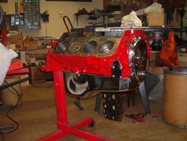
Great advice guys, keep it coming. The more great advice that is given, the easier it will be for the person building it. After a long discusion with the wife she decided that she did not like the shade of red that I painted the engine. So I found myself masking of the engine and repainting it a different shade of red. This is what it looked like before I repainted it:
Now this is what it looks like after I repainted it:
I guess it looks better the brighter red. She loves it and thats all that matters. After all this engine is going into her 86 fastback. I know I said at the begining of this thread that this engine was going to go into a 84 but, we also aquired a 86 fastback that she has taken over.
I have to be honest with everybody that is following this thread. The porting that has been done to these heads was not done by me. I had my buisiness partner port and polish these heads:
Who just happens to be my wife. I hate to say it but she has gotten pretty good at it and can do it alot quicker than I can with better results. I think she is coming after my job
She is really good at applying flow specs for the heads and she insists that all that has to be done to the intake side is a gasket match. The 86 and 87 heads flowed pretty well on the intake ports but, were restrictive on the exhaust ports. So I guess the intake side will be left alone other than a gasket match.
The next step will be installing the valves and new valve seals. I will post those pictures tomorrow evening along with the gasket match pictures.
More to come.....
Craig
IP: Logged
10:43 PM
Jan 13th, 2008
prostreet505 Member
Posts: 426 From: Wind Lake, WI 53185 Registered: May 2007
Now onto installing the valves and new valve seals:
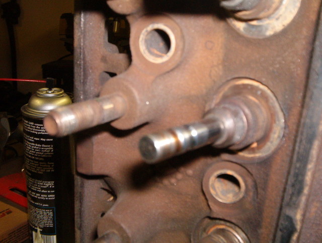
We are going to start off doing the exhaust valves. First you want to clean out the valve guide from any debris that might have gotten into them while you ported and polished the ports. So I recommend spraying alittle brake clean through the guide and then use a piece of paper towel to slide through the guide to clean it out. If you have a air compressor just use the shot of brake clean and then a shot of air to remove the debris. Then you want to slide the valve into the guide untill the valve is closed.
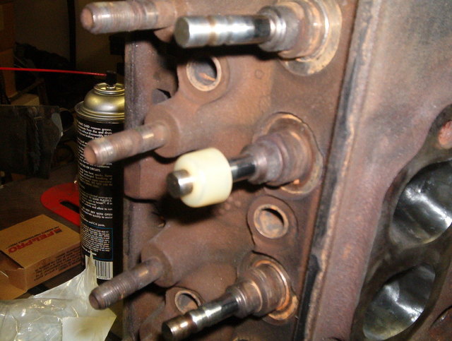
Then you can start the umbrella valve seal on the valve:
Push the plastic umbrella seal all the way down onto the head:
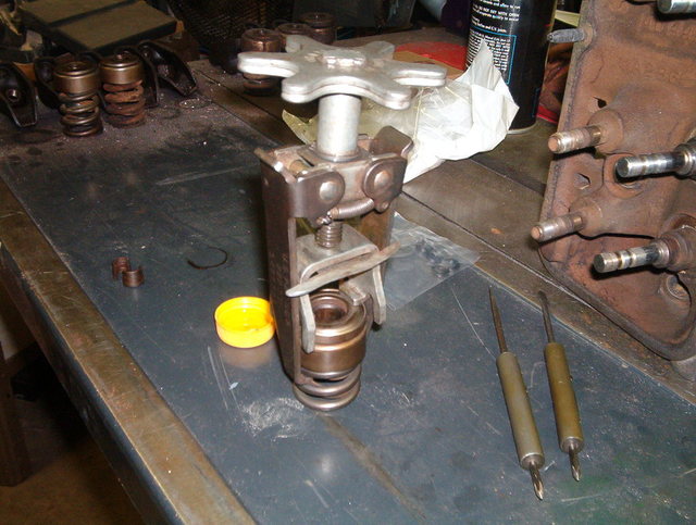
Now compress the valve spring with a valve spring compressor:
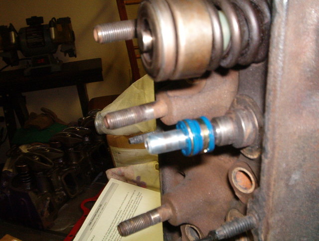
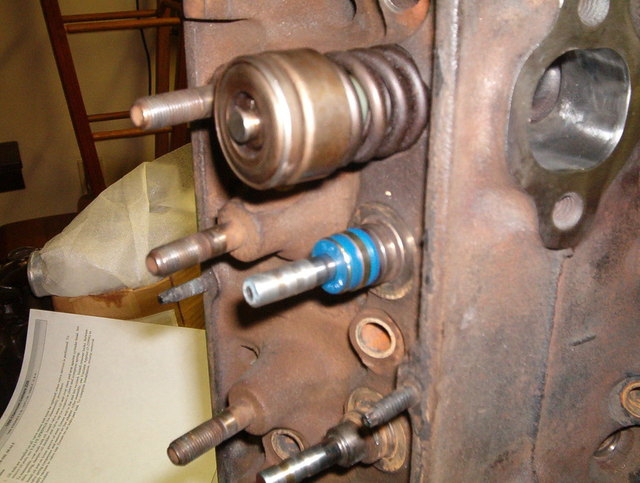
Slide the compressed valve spring over the valve:
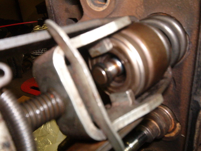
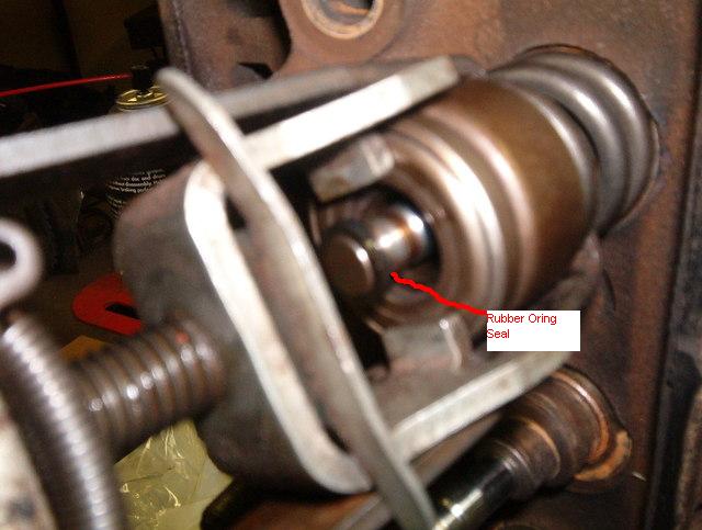
Then install the rubber oring valve seal on the valve:
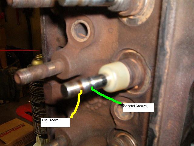
Slide the oring seal down the valve and into the second grove on the valve. Make sure you DO NOT roll the seal down the valve, it has to stay in that position:
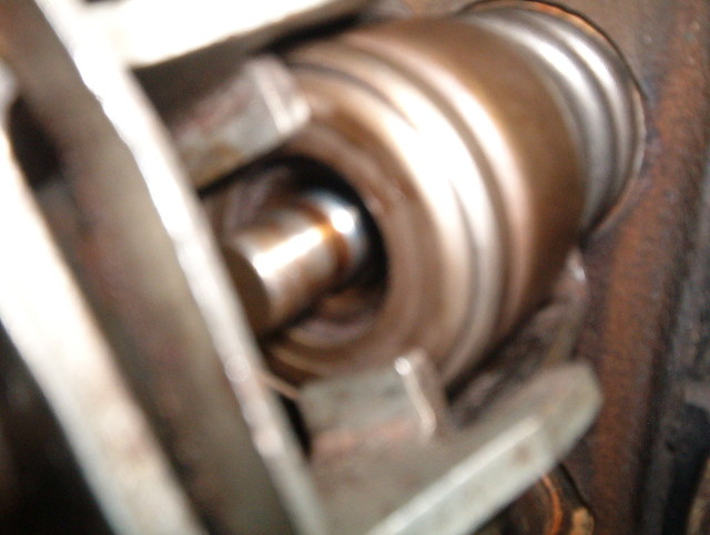
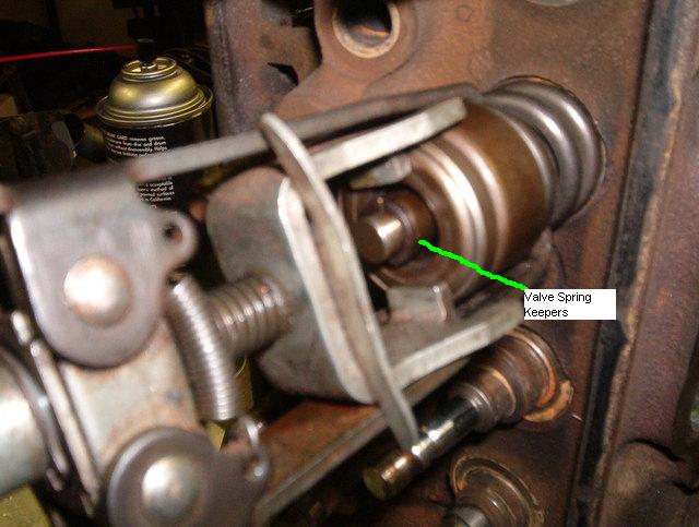
Now install the valve spring keepers or locks, "whatever you want to call them," onto the first groove of the valve and remove the spring compressor:
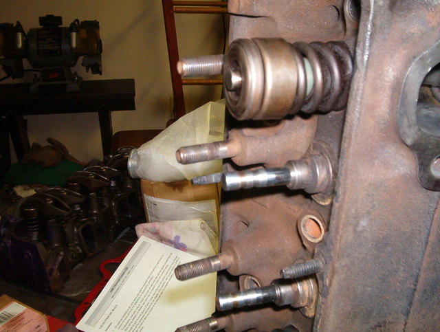
Do the same for all the remaining exhaust valves:
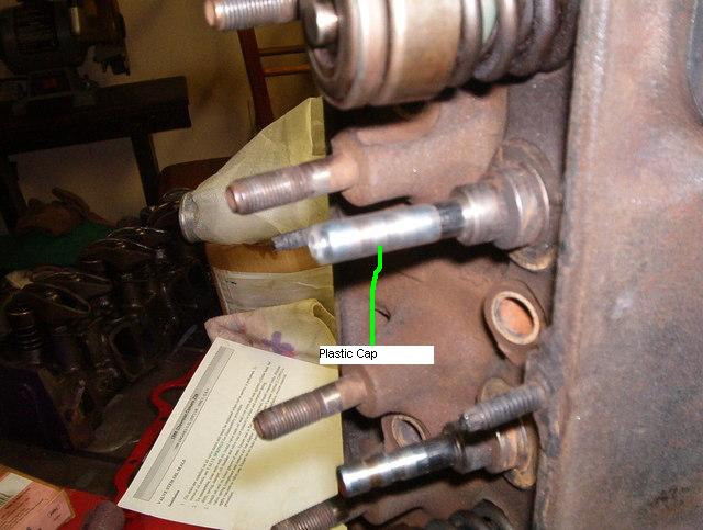
Now onto the intake valve seals. First install your intake valves into the head. In the valve seal kit there will be a small plastic cap you want to install on the valve before installing the rubber umbrella valve seal. This plastic cap is installed at the tip of the valve and covers the valve grooves so the umbrella seal is not damaged while sliding the seal down the valve and onto the head.
Install the plastic cap on the tip of the valve:
Install the rubber umbrella valve seal onto the valve:
Slide the umbrella seal down onto the head:
Remove the plastic cap from the valve:
Compress the valve spring:
Install the valve spring onto the head:
Install the rubber oring valve seal onto the tip valve:
Slide the oring down the valve and into the second groove on the valve:
Install your valve spring keepers or locks and remove the spring compressor:
Do the same thing for the remaining intake valves.
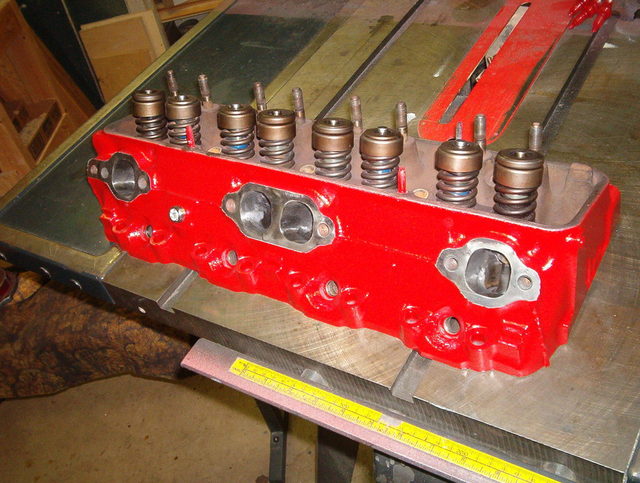
I then masked off the ports with tape and covered the springs with a old valve cover and painted the heads:


 You should be happy with it. I've also noticed that the noisy version of the Pete Jackson gear drive is not as noisy as other brands, but once the exhaust is muffled some you will be able to hear it more.