Paint the lifter valley with Rustoleum for faster oil runoff. Be advised that it will not stay on there forever, though. The oil and the heat will slowly remove it.
On a carb, the intake side is left rough to assist in atomization. The exhaust side is polished for every application.
As for painting? Why in blazes would you want paint in the engine? If you want oil to run off more smoothly, make it a smoother surface.
There are some additives, like Zmax that would be far more preferable over paint IMHO
Arn
I understand that the intake side is rough to assist in atomization but, you can still remove some of the material to give it a smoother finish which allows the air fuel mixture to move more freely into the combustion chamber. I am not going to make them look like glass.
I didn't say I was going to paint the lifter valley. I remembered reading about it sometime ago but, I could not find where I read it at. I was just curious about the pros and cons of it and if it lasted.
IP: Logged
10:54 PM
Dec 8th, 2007
prostreet505 Member
Posts: 426 From: Wind Lake, WI 53185 Registered: May 2007
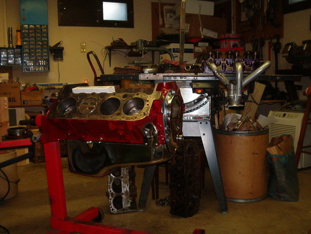
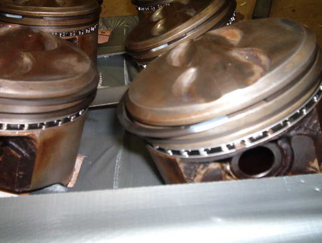
It has been a little while since I posted on this build. I have been busy with a customers car. I still didn't finish porting the heads because I ran out of porting bits and had to order some more, which I just recieved today. While I was waiting for the bits I started on the lower half of the engine. I removed the pistons and rods from the block.
Then I used some plastigage to measure the main bearings and rod bearings. The OEM main bearing clearance is Rear main cap (.034mm-.081mm) My reading was (.051mm) The clearance for the intermediate caps are (.028-.058mm) My reading again was (.051mm) and the clearance for the front cap is (.020-.050mm) and my reading was (.038mm) All the clearances are within the specifications so I bought a set of standard size main bearings and remeasured with plastigage. All is good with the new main bearings.
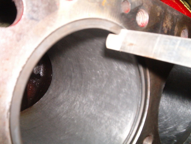
Here is a reading of the plastigage:
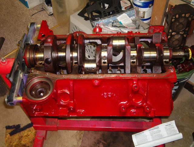
You can see the strips of green plastigage still on the main journals of the crank:
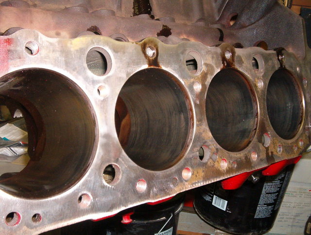
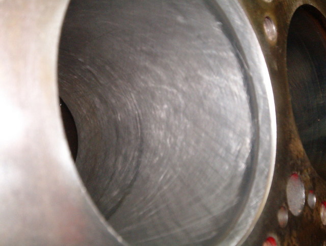
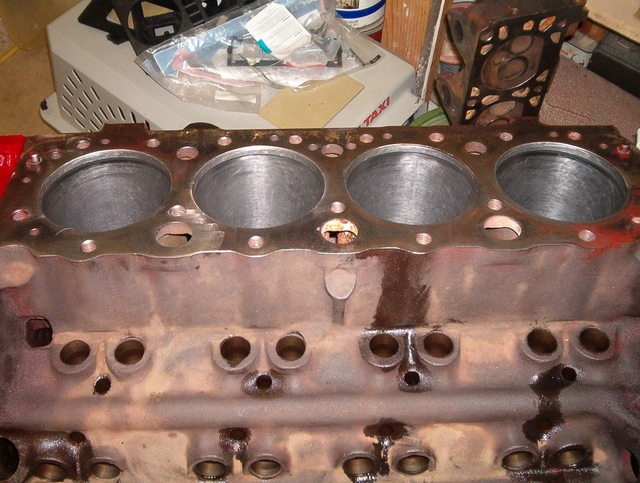
Then I decided to start the honing of the cylinders. This is what the cylinders looked like before I strated the honing:
You can still see the cross thatch in the cylinders from the factory:
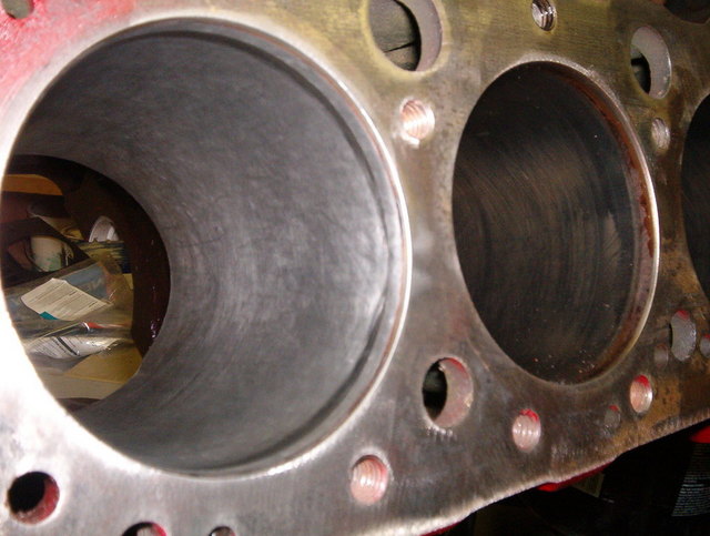
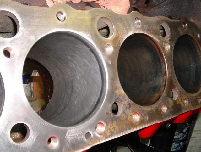
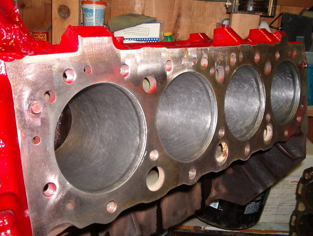
This is what a cylinder will look like after honing:
2nd cylinder:
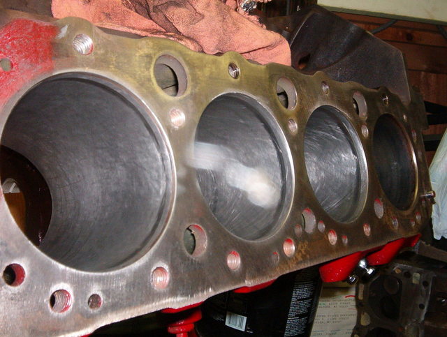
3rd cylinder:
4th cylinder:
other 4 cylinders:
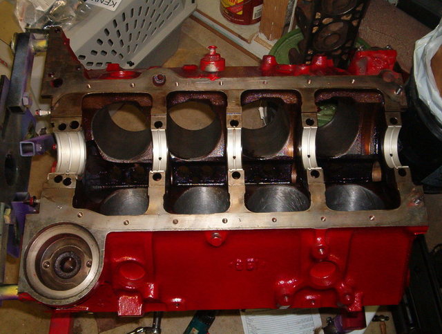
Here is the block with the cylinders honed and the new main bearings installed:
Tomorrow I will show you the specs on the new rod bearings and new piston rings.
yea, I can see some ring ridge at the top of the cyl, dont you normally want to remove this before honing? or since you are still using the same pistons doesn't it matter?
I really like what you're doing here and am keenly following everything you are doing with this build so far.
At first, I was considering a supercharged 302 project (along the same vein as Hot Rod's build, a few years ago)... essentially a short stroke/large bore screamer with on demand torque.... but, if this works out well (which it looks like its coming along fairly well), this would be a much better base building block... 327 blocks are hard enough to come by, let alone spare 283 cranks... and L99 cranks for 350's aren't too commonplace either... around here, 305's are a dime a dozen, and would be much more budget friendly...
keep the parts list updated! also if possible, a list of any specialty tools used?
thanks a bunch
JT
IP: Logged
02:59 PM
prostreet505 Member
Posts: 426 From: Wind Lake, WI 53185 Registered: May 2007
Good question about the ring ridge. Yes, there was a slight ridge in the cylinders and I did remove it using a ridge reamer prior to honing the cylinders. If you don't remove the ridge, when you go to install the pistons with the new rings you can snap and break the new rings. The thing about the ridge is that without having the block machined by a machine shop you can never remove all of the ridge. You can take enough of the ridge off by yourself with a ridge reamer and honing to safely install the pistons and rings. You should always remove the ridge in the cylinder before installing new pistons and rings or old pistons and rings. One of my next posts on piston ring end gap should give you a better idea of how you will know if you have removed enough of the ridge to safely install the pistons and rings.
Craig
IP: Logged
10:09 PM
prostreet505 Member
Posts: 426 From: Wind Lake, WI 53185 Registered: May 2007
I really like what you're doing here and am keenly following everything you are doing with this build so far.
At first, I was considering a supercharged 302 project (along the same vein as Hot Rod's build, a few years ago)... essentially a short stroke/large bore screamer with on demand torque.... but, if this works out well (which it looks like its coming along fairly well), this would be a much better base building block... 327 blocks are hard enough to come by, let alone spare 283 cranks... and L99 cranks for 350's aren't too commonplace either... around here, 305's are a dime a dozen, and would be much more budget friendly...
keep the parts list updated! also if possible, a list of any specialty tools used?
thanks a bunch
JT
Thanks JT, I am glad to see that you are interested. I did post a parts list towards the beginning of the thread, but I am going to wait until the build is almost done to update the list of parts and tools and where I aquired them from so anybody can do this themselves.
Craig
IP: Logged
10:17 PM
prostreet505 Member
Posts: 426 From: Wind Lake, WI 53185 Registered: May 2007
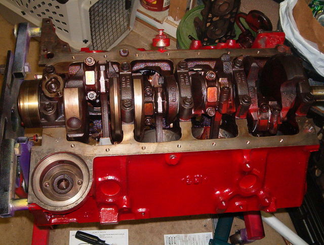
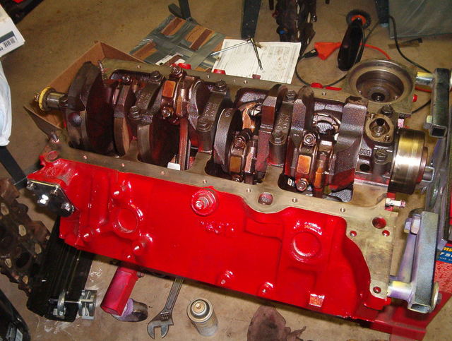
I installed new main bearings and applied some engine assembly grease to them before installing the crankshaft and torque the main bearing caps to 80 ftlbs so when you go to start the engine for the first time the bearings will be protected until the engine builds up oil pressure.
Now that the crankshaft is installed you can move on to your connecting rod bearings. Remove the piston rings for this step. The specs for the stock bearing clearance is (.033-.089mm) I used the same method with the plastigage here that I did with the main bearings and my reading was (.043mm) So I am within the specs, so I installed some new standard size rod bearings and rechecked the clearance so I won't have any future issues.
After removing the pistons and rods from the block again you can now clean your piston grooves on your piston. They do make a tool for this, but I always take a old piston ring and break it in half and use this to clean out any build up inside the piston ring grooves on the piston. It works really well. Now you can take a new piston ring and slide it into one of the cylinders so you can measure your piston ring end gap. You have to do this on all of the cylinders. You want to take 3 different measurements. The first one being at the top of the cylinder, the next one being at the center of the cylinder, and the final one about an inch lower than the center one. You have to do this with all 3 rings. I'll use one ring as an example. The stock specs are (.010-.020) my reading was (.015) in all 3 places. This also tells me that the cylinders are not dished. Which means the cylinder is the same size at the top as it is on the bottom. Dished means the bottom of the cylinder is wider at the bottom than it is at the top. This measurement also tells me I will have no problem installing the pistons with the new rings.
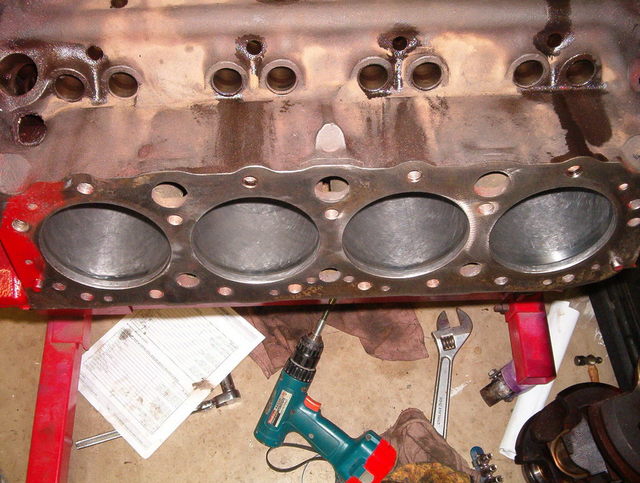
Now you can install the new rings onto the pistons. Pay close attention to the directions that come with the new piston rings, as different style rings will have different style markings on them to let you know what side faces up and what ring goove it should go in. Here are some of the pistons with the new rings installed:
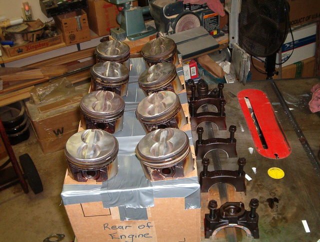
Now that the pistons are ready you can install the ring compressor on the piston and compress the piston rings into the piston. Make sure you install the piston in the same cylinder that it came out of and make sure it is facing the same direction. Most pistons have a notch marking on the top of the piston which is to point to the front of the engine. That is why I used this box to identify the piston location:
Here is the piston installed in the ring compressor:
Make sure you install some assembly grease to the rod bearings before installing the piston into the cylinder. I also coat the cylinder walls with WD40 before installing the pistons. Gently tap the piston with a rubber hammer into the cylinder and guide the connecting rod onto the crankshaft and torque the connecting rod cap to 45 ftlbs. Do this on all the cylinders. You will have to rotate the crankshaft to make it easier to install the other connecting rods. After all the pistons are installed and torqued, rotate the crankshaft several revolutions to make sure there is no abnormal binding.
This is a great thread! Thanks for doing all of this.
When I measure end gap, I use a piston upside down to square the ring up in the bore before I measure to make sure I get good numbers. I never thought of using a ring to check for taper like that. Pretty cool. I've always found taper to be largets at the top of the bore, not the bottom, but I guess if the ring gap is within spec from top to bottom the taper is acceptable.
Originally posted by prostreet505: As for your dipstick, you must have a pre 86 engine block with a drivers side dipstick. ... 86 and newer blocks came with a passenger side mounted dipstick ...
Thank you sir, that's a handy piece of information about now. PM sent.
-fh
IP: Logged
07:16 PM
gt7 Member
Posts: 277 From: suffolk, va, usa Registered: Feb 2006
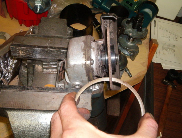
For a first time builder I would not recommend using the file to fit rings, I would recommend using the stock standard size rings.
I did use the file to fit rings but I used an angle grinder clamped in a vise. I have it plugged into a variable power outlet. Basicly a switched outlet on a dimmer switch to lower the rpm of the angle grinder from 11,000 rpm down to about 1,500 rpm. The disc in the grinder is a 1/4 inch thick. It looks a little cheesy but it works very well. The picture shows me holding the ring with one hand, but that was just for the picture, I always use two hands while filing the rings. You have to take it easy doing it this way. Just take it real slow and measure the ring alot. You can always go back and file more off, but you cannot add any material back to the ring if you take to much off.
Thanks for the complements from everybody. I am glad to see that there are people interested in the build.
Just a couple of things I noticed and you may have addressed already- Did you replace the cam bearings? Most often the cause of low oil pressure is not excessive clearance in the rod/main bearings, but the cam bearings worn thin. The exhaust crossover on one of your heads looks like it has been really hot at some point in time. Pop had that flapper valve on the exhaust in his 305 truck get stuck and warped both heads and the intake. Check them carefully for cracks caused by the excessive heat going through the thin castings. Other than that, everything looks great! Keep it coming.
IP: Logged
11:43 PM
Dec 11th, 2007
KurtAKX Member
Posts: 4008 From: West Bloomfield, MI Registered: Feb 2002
Installing a bigger cam reduces low-end torque because the dynamic compression at low engine speeds is reduced, and increasing the static compression is the only way to resolve this.
IP: Logged
05:05 AM
Russ544 Member
Posts: 2136 From: S.W. Oregon Registered: Jun 2003
Interesting buildup. as an "oldtimer" I can shed some light on painting the engine valley. don't use rustoleum, as it will not hold up and you really don't want that in the oil system of your engine. what we used in the "old days" was actually a product intended to coat electric motor armatures after rewinding them. very tough stuf. it does aid in oil rreturn, but mainly it seals the pores of the cast iron block to keep things clean down there. with todays methods of cooking the blocks, and other cleaning methods, the coating isn't really needed (although many of us old farts still do it ).
press any key to continue, Russ544
IP: Logged
11:01 AM
DPWood Member
Posts: 540 From: Aylmer, Ont. Canada Registered: May 2002
Handy thread to keep an eye on since i've currently got one 305 and 2-350's out in my shed for rebuild. The most expensive of the three was the 305....it cost me a case of beer. I'm doing up the 305 for a friend at work to put in his TA. Pretty much the same build you have going on, although...I haven't spec'd a cam for it yet because he might just stick with the stock iron intake if his budget is too tight after X-mas. We'll see.
A few well chosen parts can go a long way. The budget I'm working with is probably going to be half of yours but there are a few places I plan save $$ from what you've chosen. Just the basics of cam/intake/hedders, the best pieces I can scrounge for the money. I'll probably just stick with a good roller timing set rather than a gear drive. The carb....I can get a rebuild kit for the stock Rochester for about $50.00. Huge savings over an aftermarket carb. Too many people just say go to a Holley but the stock carb is quite capable of very good performance.
I'm Looking forward to seeing a bit more on the head porting. I've finished port matching the intake and heads and I just ordered some smaller carbides to get into the bowls. How were you going to do the valve seats?? What about the guides?? My valves only had a small amount of pitting on the exhaust side so I spent a bit of extra time lapping. None of the valves were pounded out and they felt good within the guides.
BTW... Everything I've read on porting for a carb application is consistant about leaving the intake surface slightly rough to the touch otherwise fuel can drop out of suspension and puddle along the intake tract. I finished mine off with a 60 grit cartrige roll. Leaves a finish that is about right. The exhaust side and can be done to a mirror polish to help keep carbon from building up.
And that bit about painting the inside of a block. IF you want to do it, use Glyptal...It's pretty much impervious to the oils and such inside an engine. Personally I just put a nice chamfer on all the drain holes and call it a day.
Keep up the good info
David
------------------ His Fiero: 1984 2M4 Coupe
Her Fiero: 1984 2M4 Convertible
IP: Logged
11:32 AM
jimmybpei Member
Posts: 354 From: summerside pe canada Registered: Aug 2001
one of the guys at work did the same with his s10 ... he used a vortec 305 and carbed it with an intake and headers. wh also has a 9 sec race car. he wanted to prove that he could use a305 and makie a 13 sec street truck with minimal monies.... he has said that there is a cam setup for this moter that will make it over 400hp . but he says it is pretty expensive... i'll find out his excat combo if you want as well as cam he was talking aboujt.
later jimmyb
IP: Logged
07:56 PM
PFF
System Bot
prostreet505 Member
Posts: 426 From: Wind Lake, WI 53185 Registered: May 2007
I am not planning on bumping the comp. up on this motor. I know what point you are trying to make about the low end torque. Which is correct in theroy, but in reality the loss will not be that noticeable. I have thought about using thin copper head gaskets and shave the heads to bump the comp. ratio, but I want to keep this build on a level that a novice first time builder can do everything on there own and be happy with the end result. My goal is 300hp for this build. I know for a fact that this build will reach that goal very easy and then some.
DP,
I hear what you are saying about the holley. I personally don't care for holleys. Like you said a Rochester can be a very good carb if built right. I am not going to do anything with the valve guides as they appear to be in great shape. The valve seats are still pretty good. Before I tore down the engine I did a leakdown test on the cylinders and all the cylinders turned out to be okay. I am going to reseat the valves with some valve grinding compound before I install them back in the head. I am not going to go crazy on the port and polishing because I want to keep this simple for a novice builder, but I am going to go just enough for this engine to breath properly.
Russ & DP
Thanks for the tip on the paint for the lifter valley.
Craig
IP: Logged
11:34 PM
prostreet505 Member
Posts: 426 From: Wind Lake, WI 53185 Registered: May 2007
one of the guys at work did the same with his s10 ... he used a vortec 305 and carbed it with an intake and headers. wh also has a 9 sec race car. he wanted to prove that he could use a305 and makie a 13 sec street truck with minimal monies.... he has said that there is a cam setup for this moter that will make it over 400hp . but he says it is pretty expensive... i'll find out his excat combo if you want as well as cam he was talking aboujt.
later jimmyb
If you can find out what setup he is running I would like to hear about it.
Craig
IP: Logged
11:39 PM
Dec 16th, 2007
prostreet505 Member
Posts: 426 From: Wind Lake, WI 53185 Registered: May 2007
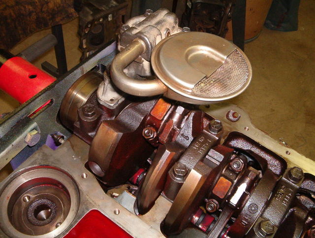
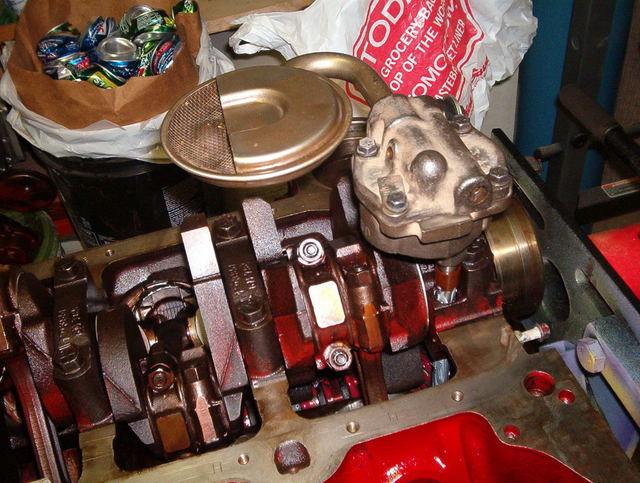
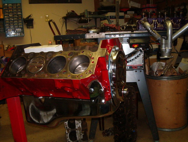
Now you can install the oilpump and pick-up tube and the oil pump drive onto the engine. I took the oilpump apart and cleaned it up before installing it. I also packed the oil pump gears with assembly grease before I put it back together. If you don't feel comfortable taking the oilpump apart you can buy a new one for about $20.00
I installed the oilpan that I bought on ebay for $25.00 with several bolts so no dirt gets into the lower half of the engine.
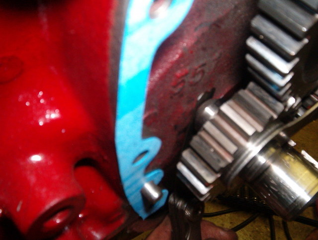
Now you want to install the crank gear on the crankshaft. You can use a large socket to tap the crank gear on.
Then you can lube up the camshaft with the assembly grease. I used the grease that came with the edelbrock cam kit. If you don't they say it voids the warranty.
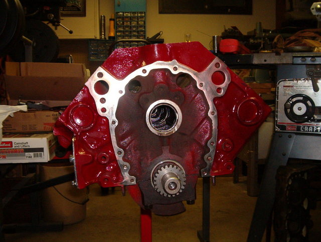
Now you can install the camshaft into the block. Becarefull not to knick the bearings on your way in. Just take it nice and easy. It might help if you use 3 long bolt and thread them into the front of the camshaft to help you balance the camshaft while installing it.
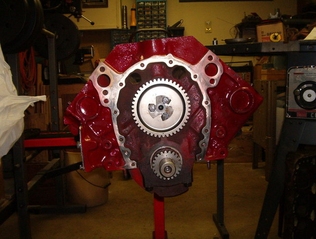
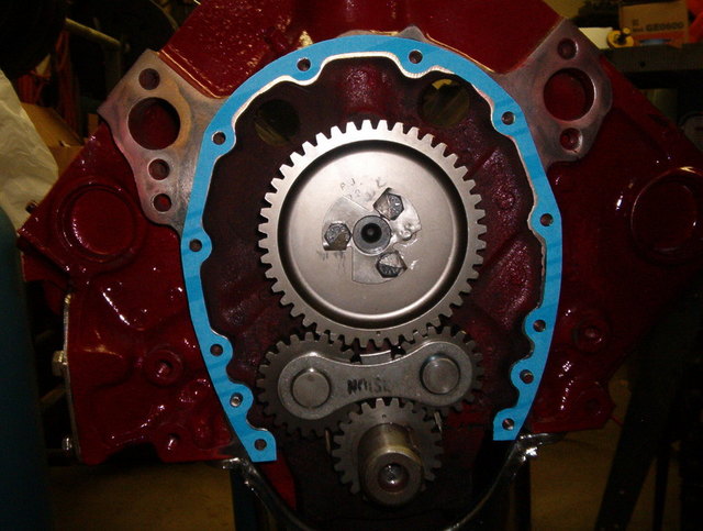
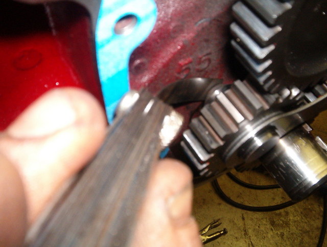
Install your camshaft sprocket:
Make sure you line up your timing marks, dot to dot. Slide the idler gears in place and torque the camshaft sprocket bolts to 20 ft lbs.
Install the timing cover gasket to the block. I use 3M weatherstrip adhesive to make the gasket stick to the block.
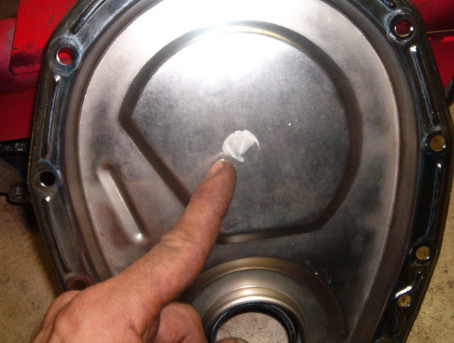
On a gear drive setup there is no timing chain to hold the camshaft in place so it does not walk out of the block. Therefore you need to get a cam button. The cam button slides in the front of the camshaft and pushes against the timing cover to hold the camshaft in place. Add some assembly grease to the cam button and install the timing cover.
Now remove the timing cover and the grease should leave a mark on the timing cover if the button does not have to be shimmed.
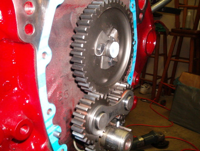
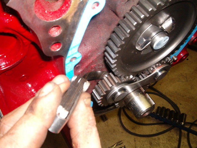
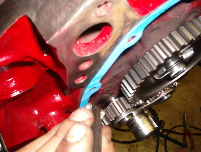
We now have to check the clearance on the floating idler gears. The idler gears also get held in place by the timing cover.Now slide the idler gears out about 1/4 inch and then reinstall the timing cover.
Remove the timing cover again and check for clearance behind the idler gear. You should have .015 of an inch clearance in between the block and the rear shaft of the left side of the gear.
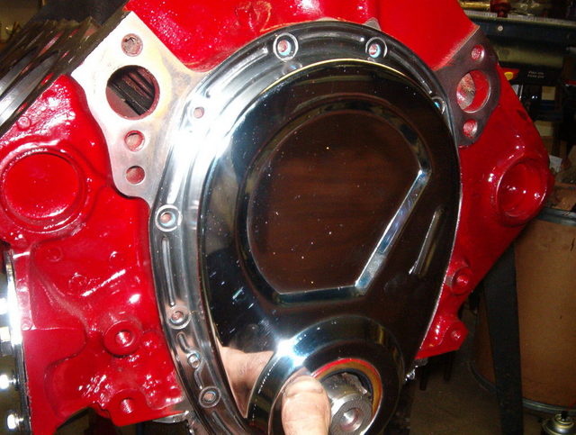
If the clearance is good you can reinstall the timing cover and torque bolts to 8 ft lbs. If the clearance is not enough you have to grind some material off the rear shaft of the left gear to get the clearance to .015 of a inch. In this case the clearance is good, so I installed a new crank seal in the timing cover and applied some assembly grease to the timing gears and reinstalled the cover onto the engine.
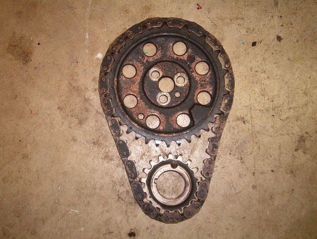
You can see how much more durable and accurate the gear drive is compared to the stock timing chain.
Wow! Great thread Craig, I appreciate the detail you go into in a step by step fashion. You make everything black and white (or maybe red and chrome). Thanks for taking the time to build this thread and also for sidestepping the flames so admirably.
With the pistons out and new rings, I would have expected you to do some weighing and balancing the piston assemblies, but, from what I've read you haven't done that. You have a reason, of course, and maybe you can explain the relative merits.
Arn
IP: Logged
09:27 AM
tjm4fun Member
Posts: 3781 From: Long Island, NY USA Registered: Feb 2006
nice writeup. since you have written this with the novice in mind, just a couple of things for their bag o tricks when assembling and checking. when checking the piston bore, do it before the crank is installed, so you can use a piston to square up the ring at the various points in the bore for the checks. the ring MUST be square for a true measurement. when doing the final install of the piston, put a 1 ft lenght of 3/8 rubber hose on the rod studs to help guide it over the crank bosses without worry of knicking it. If you have done bolts, use some wooden dowels in place of the studs with a small piece of hose at the base to guide the end over the crank. install the studs in the rods after they are in place. Clevite77 is one of the best assembly lubes for all bearing surfaces. sticky, yet will not harden and block the oil flow. (looks suspiciously like the lube that came with your cam, cause that;s what cmae with mine, and it was the exact color and consistency of the stuff in my bottle I used for the rest of the stuff) for the cylinder walls, wet a clean rag with regular oil and wipe it down, just enough for a film there for the install. the wd40 is fine for the ring compressor, light and won't cake the rings. in a pinch, good ol vaseline works great to pack the oilpump gears with for the initial install.
just a few old time things a novice can use, costs nothing and can save some damage during the asembly.
As for the painting the valley, it does help, but what helps more is chamfering the return holes on the heads and the valley, and making sure there is no restriction thru the head gasket, the hole in the gasket is often smaller than the returns. the most oil tends to get trapped in the head area on a high rpm motor.
IP: Logged
09:53 AM
fiero go fast Member
Posts: 1728 From: Royersford, PA Registered: Apr 2002
A few quick questions, are most torque specs for internals the same between stock engines (302, 305, 327,350, etc etc)?
Secondly, is the main purpose for filing the rings just to get your clearances closer within spec? For instance, buying an overside ring, and then filing it to what is needed.
Great thread, keep up the great work with the detail and such. Plus for you.
Thanks, Matt
IP: Logged
01:05 PM
luvin_my_fiero Member
Posts: 437 From: sneads ferry,nc usa Registered: Feb 2005
one thing i would have done is tack weld the pick up tube onto the oil pump. that bit me in the ass one time on a 350 and ever since,mine all get tack welded. mine was a tight fit when assembled and everything but im telling you from experience, they can still come loose.
though already installed i usually wouldnt recommend using a gear drive. Though it sounds cool, it actually shortens engine life by inducing harmonics into the valvetrain and motor, hence why you never really see any racer running them, kind of a show-car cool sound thing anymore.
The 305 heads will need quite a bit of work to make use of that cam, definately need bowl work and chamber clean up. Heads are the power, you can have the most expensive bottom end and the best cam in the world but it wont mean anything without good flowing heads. Also screw in rocker studs should be a must, the increased lift and spring pressure with that cam can rip the studs right out.
I have seen build ups with the 205 producing 300hp or more, its entirely possible, it just easier with a 350. bad thing with the 305 is the long stroke/ small bore is low rpm power, even with the reduced weight its just not that great of a combo for rpm but good as hell for low rpm torque. But the HO 305 is the way to go if building it because of the flat-top pistons netting a higher compression ratio. with the right parts and combo you can do 300hp out of a 305
------------------ Fiero- mild 2.9 160hp Caprice- wild 383 500hp --Adam-- ASE Certified Technician IM AOL: FieroGT5speed
[This message has been edited by GTFiero1 (edited 12-17-2007).]
IP: Logged
04:26 PM
fiero88v8 Member
Posts: 59 From: Nfld., Canada Registered: Mar 2005
I think you are doing a splendid job on the rebuild as well as the step by step walk through. If anyone doesnt like what your doing or are being negative about your "very professional job and attitude", well.....Im sure they know what they can do. keep it goin.its very interesting
IP: Logged
09:56 PM
PFF
System Bot
prostreet505 Member
Posts: 426 From: Wind Lake, WI 53185 Registered: May 2007
though already installed i usually wouldnt recommend using a gear drive. Though it sounds cool, it actually shortens engine life by inducing harmonics into the valvetrain and motor, hence why you never really see any racer running them, kind of a show-car cool sound thing anymore.
The 305 heads will need quite a bit of work to make use of that cam, definately need bowl work and chamber clean up. Heads are the power, you can have the most expensive bottom end and the best cam in the world but it wont mean anything without good flowing heads. Also screw in rocker studs should be a must, the increased lift and spring pressure with that cam can rip the studs right out.
I have seen build ups with the 205 producing 300hp or more, its entirely possible, it just easier with a 350. bad thing with the 305 is the long stroke/ small bore is low rpm power, even with the reduced weight its just not that great of a combo for rpm but good as hell for low rpm torque. But the HO 305 is the way to go if building it because of the flat-top pistons netting a higher compression ratio. with the right parts and combo you can do 300hp out of a 305
Ummmm Okay,
For starters, I will not need screw in studs. The stock studs will work perfectly fine along with the stock springs. Per edelbrocks website they say that you should use the sure seat valve springs or the stock valve springs with this cam and lifter set up. Trust me I used this set-up before, And the gear drive. " Show car sounds cool thing"?? I have never heard of it shortening engine life and valve train. A gear drive set-up is the most dead on accurate timing set-up you can get that is good up to 8000 rpm. A gear drive has no chain to stretch under heavy acceleration which intern keeps your timing dead on.
The 305 is not a low end torque engine it is an upper rpm band engine, and has the same stroke as a 350 just a smaller bore. This engine is the L69 engine code which makes it the 305 HO
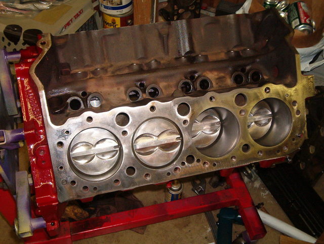
As for the heads, they are going to be ported and polished and they do not need alot of work. The 86 305 HO heads flow pretty well to begin with, but since everbody has been anxious about the heads I'll show a couple of pictures of the work so far.
No more pictures of the heads untill I have them done. Then I will go through the step by step process.
Craig
IP: Logged
11:26 PM
prostreet505 Member
Posts: 426 From: Wind Lake, WI 53185 Registered: May 2007
A few quick questions, are most torque specs for internals the same between stock engines (302, 305, 327,350, etc etc)?
Secondly, is the main purpose for filing the rings just to get your clearances closer within spec? For instance, buying an overside ring, and then filing it to what is needed.
Great thread, keep up the great work with the detail and such. Plus for you.
Thanks, Matt
The torque specs may be close on certain engines, but I would still double check your torque specs with a manual for the year of the engine. Your right on target about your file to fit ring question. Thanks for the compliment.
Craig
IP: Logged
11:32 PM
prostreet505 Member
Posts: 426 From: Wind Lake, WI 53185 Registered: May 2007
With the pistons out and new rings, I would have expected you to do some weighing and balancing the piston assemblies, but, from what I've read you haven't done that. You have a reason, of course, and maybe you can explain the relative merits.
Arn
Good question Arn. I didn't want to get into any balancing or blueprinting of the engine, because that can start to get very involved and tricky. I mean we are talking about grams coming off a piston to make them equal. If a person does not have an accurate way to measure this it can cause alot of problems. Plus I want to keep this build under $2000.00 You know as well as I do that I could go on and on about the internals of the engine to make it better, but along with that comes the price tag.
Craig
IP: Logged
11:42 PM
prostreet505 Member
Posts: 426 From: Wind Lake, WI 53185 Registered: May 2007
one thing i would have done is tack weld the pick up tube onto the oil pump. that bit me in the ass one time on a 350 and ever since,mine all get tack welded. mine was a tight fit when assembled and everything but im telling you from experience, they can still come loose.
Good thing to keep in mind. I never had that happen to me yet. But there is always a first. Thanks for the tip
IP: Logged
11:44 PM
CTFieroGT87 Member
Posts: 2520 From: Royal Oak, MI Registered: Oct 2002
Nothing more reliable than a good gear drive, especially at that rpm. Current tensioners might be good, but man can that chain wriggle like a snake at those speeds!
nice writeup. since you have written this with the novice in mind, just a couple of things for their bag o tricks when assembling and checking. when checking the piston bore, do it before the crank is installed, so you can use a piston to square up the ring at the various points in the bore for the checks. the ring MUST be square for a true measurement. when doing the final install of the piston, put a 1 ft lenght of 3/8 rubber hose on the rod studs to help guide it over the crank bosses without worry of knicking it. If you have done bolts, use some wooden dowels in place of the studs with a small piece of hose at the base to guide the end over the crank. install the studs in the rods after they are in place. Clevite77 is one of the best assembly lubes for all bearing surfaces. sticky, yet will not harden and block the oil flow. (looks suspiciously like the lube that came with your cam, cause that;s what cmae with mine, and it was the exact color and consistency of the stuff in my bottle I used for the rest of the stuff) for the cylinder walls, wet a clean rag with regular oil and wipe it down, just enough for a film there for the install. the wd40 is fine for the ring compressor, light and won't cake the rings. in a pinch, good ol vaseline works great to pack the oilpump gears with for the initial install.
just a few old time things a novice can use, costs nothing and can save some damage during the asembly.
As for the painting the valley, it does help, but what helps more is chamfering the return holes on the heads and the valley, and making sure there is no restriction thru the head gasket, the hole in the gasket is often smaller than the returns. the most oil tends to get trapped in the head area on a high rpm motor.
I agree with everthing you have added except the vaseline in the oil pump. I have ran into the vaseline getting into the oil filter and restricting it. I'm not saying the method is wrong because tons of people use this method with no harm done. But vaseline does not break down as easy as assembly grease does. Thanks for the input.
Craig
IP: Logged
11:56 PM
Dec 18th, 2007
flames4me Member
Posts: 915 From: Woodbury MN / Hammond WI Registered: Jun 2005
hey I have a quick question for anybody, can you bolt on a big block oil pump for better oiling? I have heard of people putting BB oil pumps in their small blocks but is it a direct fit, or is there something else that has to be done? thanks
IP: Logged
03:57 PM
Alex4mula Member
Posts: 7410 From: Canton, MI US Registered: Dec 1999
My dad has one of the last 400 crate engines ever built installed in a '75 Jaguar and currently running under a TPI intake manifold. He installed a double roller timing chain when the engine was brand new. It now has over 300,000 miles on it and will burn the tires in the Jag as long as you hold your foot down...
I'm not convinced that there's anything wrong with a timing chain that compromises its durability for a streetable engine. Its accuracy is defined by stretch, which will be minimal with near stock valve spring loads.
IOW, I think that the gear drive is overkill and that the increased noise will be a compromise that is not offset by measurably better performance.
That type of gear drive tries to pull the right bank gear through the mesh between the crank and cam gears. This puts more lateral loading on the cam snout than you might think. Is it as much as a chain? Who knows? The torque transmitted is the same either way.
I think the best type of gear drive is one with a single fixed idler, but one of those would be out of budget for this build...


 ).
).