After a few changes along the way, I am now moving into the next phase of my Lambo build. Originally I was planning on doing a Murcielago build, but this has now evolved into an Aventador build. Both great looking cars, but I must admit the Aventador is a few levels above the Murcielago. There are more aftermarket parts available for the Murcielago, but since this build will undoubtedly take quite a few years, I imagine reproduction parts will become available as time goes on.
This project has been divided into three parts:
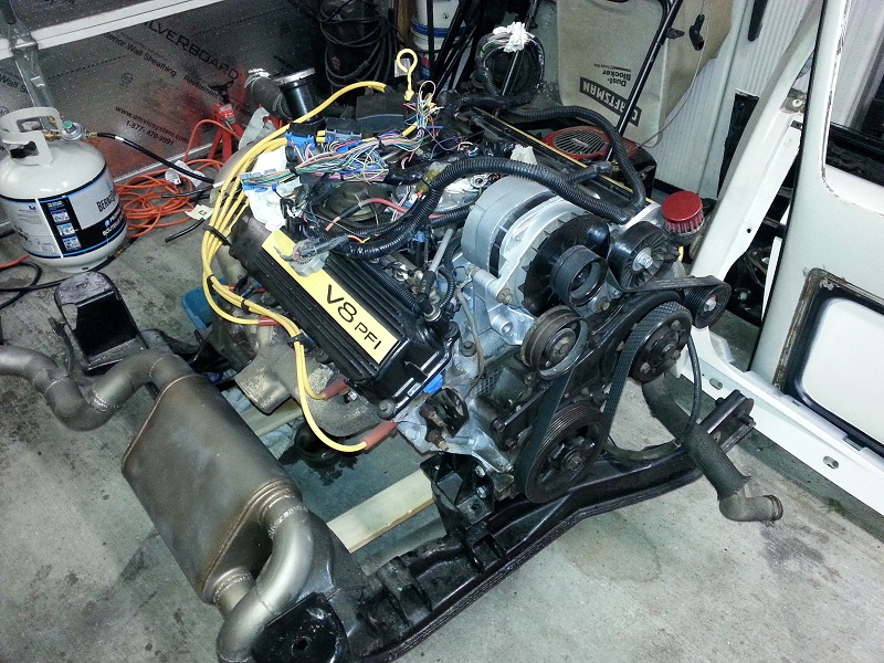
1) Initial engine swap. I just couldn't leave the Iron Duke in this, so I decided to start the project by installing a 4.9L V8. This ensured that I would at least have a little horsepower once the body kit was completed. It actually also helped me learn more about the Fiero since this is the first one I've owned.
2) The body kit. This is the main part of the build and the focus of this thread. I am planning on keeping the build as close to the real Aventador as I can, but reserve the right for some artistic license when required.
3) Longitudinal engine swap. Once the body kit is finished, I plan on taking advantage of the 12.8" stretch. I plan on building a new cradle for the engine, and getting the entire engine build running before actually installing it. I'm expecting the engine build to take quite a while and I don't want the car out of action longer than it has to be. Once the engine/tranny are up and running then I'll do the install during the winter while the car is parked. Ideally I'll be looking at installing a 760Li V12. Though the exact engine choice will be confirmed once I finish the body kit and can get accurate measurements.
Here is the donor car, with freshly installed 4.9L V8.
...and the teardown begins...
[This message has been edited by Neils88 (edited 05-21-2015).]
Looking forward to the build. If and when you get rid of your 4.9L I'll be more than happy to take it off your hands
Not a problem...would you like me to install it for you too?
Actually, I haven't decided what I'll be doing with it. Since it will be on the cradle and complete (everything from the suspension, all the way to the computer)...it should make for a quick weekend swap for any future projects. I might make it available for someone else to enjoy or keep it for my next project.
Made a little progress today. Managed to get the passenger door off, both rocker panels and both front fenders. For anyone who hasn't removed any of these parts, be aware that the rocker panels and two points on the bottom of each fender are all held on with aluminum rivets. Easiest way to remove them was to drill them out.
Glad to see that there is no rust to deal with. Even the trunk is completely solid.
I know...most people will shake their heads at me for that, but my goal with that phase will be a full engine build. I'm expecting that part to actually take at least a few years in itself. Since it'll be built on another cradle and won't go into the car until it is absolutely ready to go in, I can spend most of that interim time driving and enjoying the car with the 4.9. The engine build project is also something I've really wanted to do. Another thing to note, since the engine is really always on display in an Aventador, it deserves to have a great looking longitudinal engine
quote
Originally posted by gen2muchwork:
I enjoyed your 4.9 swap thread. I'm looking forward to this one.
Spent the last few days removing the front bumper and the front roof panel. Someone is coming to pick up all the panels this weekend, so I'm being somewhat careful not to damage anything. I've also removed the seats, seatbelts, interior trim and the roof liner (required in order to remove the roof panel).
I used a heat gun and small flat screwdriver to gently remove the adhesive under the A-piller panels. I found it was soft, but not too tacky. It just takes a while to slowly remove the adhesive while resisting the urge to "pry" the A-pillars off with the screwdriver.
Tomorrow I'll work on the rear roof / fender panel. Not sure yet how that one comes off. You learn a lot by stripping the car down to the space-frame!
Today was a late day getting started, so the only thing on my agenda was getting the rear roof panel off (is there a better name for that part?). No issues taking it off. Like anything, you have to take the first time slowly and work around it methodically locating all the points where something is still connected (like the fuel door release cable).
Next, I'll finish stripping the front part of the car, including the headlights, bumper, radiator etc. Then I'll finish emptying the interior. Finally, I'll be pulling the engine and I'll be ready for the stretch.
My garage is insulated, but without heat it gets as cold as it is outside very quickly. If you have to deal with a cold garage, I recommend getting one of these indoor propane heaters. I picked this one up on sale at Lowes for $100. 15,000-60,000 BTU. It can warm up my two car garage in about 5 minutes! I should have bought one last year. I've been using it all week + weekends, and still haven't used up the first tank of propane (which I can get filled at Costco for $10). So pretty cost effective for quick heat.
I finished removing a majority of the interior, including the full dash. I may actually replace the HVAC system with something more modern so I can introduce some automation (i.e. buttons instead of the stock sliding bars for control). I've also labeled all the wires/connectors so that it'll be a little easier to hook up the new controls. There will be lots of new stuff going in too.
The next four pics show the condition of the floor on both the drivers side and the passengers side. Everything looks to be in great condition.
...as good as everything is, there is this one spot that I'll have to investigate. From a quick check, it appears only to be on the surface in that one spot and it looks completely solid underneath.
The front end is now stripped of the bumper, the lights, the rad fan and the rad support. I'll be draining the system and pulling the engine very soon...
It's important to label all wiring harness connectors so I have a fighting chance to hook up the new components.
I had some issues with the back glass. Originally I had planned to save it since even though I didn't need it for the build, I figured someone could use it. However, after a day and a half of trying to remove it I finally gave up and decided to break it to get it out. While I had decided to break it to remove it, I had forgotten what happens to safety glass when it breaks...took me another few hours cleaning up glass from the engine, from inside the car, from under the car...and from all around the car. When safety glass breaks, it leaves no doubt in your mind that it is broken.
I had better luck with the windshield. Danyel suggested using rubbing alcohol on the urethane to soften it. Between that and a utility knife, I was able to quickly cut the windshield out. That's actually the first time I've ever picked up a windshield...a lot lighter than I expected.
I'm still waiting for the panels and interior to be picked up...I'm going to be a little bit on hold until they are out of the garage. I was hoping to start the stretch by this weekend, but I still have to remove the engine. I'll get it ready to go (drained, unbolted, etc) that way I should be able to pull it in a relatively short time.
I wanted to change the steering wheel and come up with something that would ultimately look more like the stock Aventador steering wheel. I managed to pick up a 2006 Pontiac G6 steering column / steering wheel to the local pick-n-pull for $25. Great price for a wheel / column with a number of key features. First, it is already leather wrapped. It's in pretty good shape, but I will most likely get it re-wrapped so it will be freshened up and colour matched to the interior. Secondly, this wheel has quite a few buttons that are for the most part generically labelled. This will perfect for me to decide what I want to connect them to (lot's of fun ideas there ...this will all come together later in the build). Also another key thing...the two sets of wires from the airbag are perfect for me to re-purpose into paddle shifter wires. I'll be doing a little surgery to install the paddles on the backside of the steering wheel. Having the two sets of wires saves me a ton of effort. Lastly, this column comes with Electronic Power Steering (EPS). I had been thinking of adding power steering due to the ultimate size of the front tires. If I keep them true to the Aventador, the fronts will be 19x9 (255/35 ZR 19)...which obviously won't be fun at slower speeds, so power steering will help. The great thing about EPS is almost everything is right there on the steering column. I will need to do a number of things to get the EPS running. The control module unfortunately sits a little low and will likely get in the way of my feet, so this will have to be moved. I will also need to create a circuit that will convert the vehicle speed into readable GMLAN serial data. The controller requires this data to vary the amount of power steering dependant on the vehicle speed (more assist at low speeds, less at higher speeds).
I've removed the ignition / steering lock mechanism. This will make my life a little easier for integrating the new steering column. The car will be utilizing an RFID starting system, with start button. The steering lock is removed since there is no key used once you climb into the car. I could change this at a later date and install a solenoid operated steering lock...but that will be something to develop later. I will have to add about 3 1/2" to the length of the column, and will have to adapt the end to safely secure to the U-joint. Likely I'll use the bottom 4" of the stock Fiero column and integrate it with a piece of the G6 U-joint to make an extension / adaptor.
With the airbag removed, I will make a custom fiberglass center plate that will be leather wrapped with the Lamborghini logo. I will also make sure the horn mechanism is still functional.
I wrote earlier that this column came out of a 2006 Pontiac G6, since that was what was written on the side of the car at the "Kenny U-Pull" where I get my parts. However, I'm beginning to think they mislabelled the car and it was actually a 2006 Chevy Cobalt, since the column matches Cobalt column pics online and is a slightly different than the G6 column.
I finally finished the mechanical portion of the install. I must say, I really love the look of the new steering wheel. I had to change the rear support bracket since it uses a single long bolt that is used as a pivot point for the tilt steering function. The support is located at the same location as the two rear support bolts are on the Fiero. In order to get as much rear height as possible, I cut away a section of the dash frame and welded in a new raised support beam. The bolt then feeds through two supports welded to the beam.
The Fiero column and the Cobalt column have different steering U-joint connections and, conveniently, the Cobalt column is 3.75" shorter. This made it easy to create a small adapter that fit over the end of the Cobalt shaft and into the existing Fiero U-joint connection. I simply welded the Cobalt U-joint connector to a small section of the Fiero shaft that I had cut off. (Just need to dress it a little, and paint it.)
The wheel feels great and works well from lock to lock. Next steps are to make the necessary wiring connections for the lights, wipers, etc. The power steering will take a little more effort. I'll save that discussion for later.
Quick change of gears....someone came and picked up most of the panels, lights, etc. from the Fiero that were blocking space in the garage. Now that I finally have some room to work it's time to get the stretch done. The body kit should be finished by the middle of next week, so hopefully I'll receive it within the next couple weeks. Unfortunately the body kit will probably take up most of the free space I have so it's important to get the cradle and the subframe stretched as soon as I can. The kit wheelbase is 105.25", which is about an inch less than the real Aventador. This means the total stretch on the Fiero will be 11.85".
This afternoon I managed to get the engine disconnected, so hopefully I'll be able to drop the engine tomorrow and get the cradle and subframe cuts made. I won't buy any metal stock until I get some exact measurements of the frame rails, after the cuts are made.
Got around to pulling the engine. I also took the axles and suspension off the cradle. Both will have to be replaced for widetrack suspension. I also removed all remaining obstacles around the area where the subframe will be cut (clutch / brake lines, vacuum line, fuel vent tank).
With the cradle stripped down so that it could lay flat, I built a small jig to hold the front cradle mounts at the same distance and height. This will ensure that correct alignment is maintained when I weld in the metal inserts.
[This message has been edited by Neils88 (edited 03-23-2015).]
This is the moment where you know you are committed...
I'm going to finally strip off that old insulation on the back of the firewall. Not sure if I'll reinsulate or use the aluminum shield that others have done. I think now is also a good time to replace all of the rear 28 year old brake lines. They are starting to show their age.
Added to my favorites ..... will be doing the same stretch (8in though) to mine after the summer fiero season .... keep the pics and info coming. regards Danyel
First part of the stretch is finished. It is important to make scribed reference marks prior to making the cuts. Also, remember that the stretch is with respect to the center of the front cradle mount holes. If you change the angle of the mount after the cut (which can make it easier to weld in the insert piece), remember that scribe marks on the top or bottom of the cradle may no longer give accurate stretch measurements. This is the one part where you need to measure multiple times, both before you tack weld the inserts and after. Ensure the stretch lengths are correct and equally important, make sure diagonal measurements are the same.
Ok...time to get some better ventilation in the garage for when I'm welding....
The engine cradle rails and the upper frames are relatively simple since they are all just straight beams. The main issues for the stretch involve the lower frame rails. They lie at a slight angle. When cut and separated, the frame rails can no longer use a straight beam if you want the beam to sit inside the rail at least several inches. The best solution is to weld up inserts with angled ends:
You'll still need a little force to get them into place. I used a 6000 lb ratcheting tie down strap...in conjunction with some spirited hits from the hammer to encourage the lower rails to get to the right position. Don't forget...lots of scribe marks before you cut the rails and measure, measure, measure!!!
The drivers side inserts are starting to look more finished. I will be adding an angled support post at a later date once I get a better idea of the exact positions of some of the mechanicals in that area.
The rails are now finally complete for the stretch. I was able to keep the same feel as the stock rails and just extend it. You won't be able to see them once the body is on, but I still wanted them to be as seamless as possible. I'll leave the sheet metal open for now. Once I mount the dual radiators I'll be able to see better what I should do with the sheet metal to give the best function and appearance. Same with the angled support braces. I need the radiators and body panels to determine what the best configuration is for strength and functionality.
I never mentioned anything about the welding. Welding inserts can be a little tough since the inserts are likely to be 1/8" while the spaceframe uses 16 gauge sheet metal. The spaceframe uses sheet metal stamped into shape and welded with other stamped pieces creating a structurally strong boxed frame. There is a bit of a trick to weld 1/8" to 16 gauge (about 1/16") metal. Set the heat and feed as you would normally for welding 1/8" steel. Start the welding on the 1/8" metal and then push the bead over onto the 16 gauge momentarily. If you do it right the molten metal wave will wash over the light gauge metal, and there will be sufficient heat in it to melt and weld to the lighter gauge metal. Weld small lengths at a time, no more the 1/4 - 1/2". Too much heat and you'll blow holes through the light gauge metal...then you get to play "chase the hole" (Anyone who has tried to weld light gauge metal will know what I mean.) Pausing every 1/4-1/2" for the bead to stop glowing will help ensure that it doesn't build up too much heat in the light gauge. There are a number of good YouTube videos showing how to do this. Practice lots before trying to weld the spaceframe for the first time.
Another trick (I learned this one from Steve ) is to clamp a copper pipe behind the light gauge metal where you are going to weld. It will help draw heat away from the weld location and help limit blow-though. Most areas of the spaceframe are tough to get a pipe into though so this method won't help too much unfortunately.
I've been taking a little bit of time to work on some of the programming that's required, while I'm waiting for the body kit to be delivered. I plan on using a number of computers / microprocessors to handle many of the functions of the car. Here's a list of "modules" I'll be using:
DDM - (Dash Display Module). I'm using a PICO ITX for control of the dash display. The PICO ITX is a full computer system that is the size of a pack of cards. I can run a compressed version of Windows XP or Windows 7, stripped down with just relevant functions installed to improve performance. The system has 1 GB of RAM, runs at 1 GHz, has four USB ports and even an HDMI output. My goal is to replicate the real Aventador dash fairly closely. (There is a link to a screen capture video below)
DCM - (Dash Control Module). I'm using an Arduino Uno for connecting all sensor data (VSS, RPM, Oil pressure, Fuel level, etc.) to the DDM through one of its USB ports. The Arduinos are great small, fast running microprocessors that is perfect for reading and outputting both analog or digital signals to and from various sensors and equipment. Some signals will require some sort of processing before being sampled by the microprocessor. Analog signals are converted to a 10 bit integer value (0 - 1023), while digital signals are stored as a simple boolean value (true / false).
SCM - (Steering-wheel Control Module). This module will handle all controls from the steering wheel buttons, plus light and wiper stalks. Functions include: wipers, lights, cruise control, stereo control and dash interface. I'll be using an Arduino Mega to connect to the steering wheel functions. The Mega is similiar to the Uno. But whereas the Uno has 6 Analog and 14 digital I/O ports, the Mega has 16 Analog and 54 digital ports.
GMLAN. This module uses an Arduino Uno with an attached CAN shield to allow the creation of a GMLAN, as is normally used to communicate with various devices on a GM car. I'll need this to communicate with the power steering system that is installed. I'll talk about this setup at a later date.
BCM - (Body Control Module). This module also uses an Uno and interfaces with all of the various body components of the car, such as the active spoiler and vents, interior lights, door locks and door position sensors, etc. Two of the Arduinos will also run the smaller LCD displays that are normally seen to the sides and slightly forward of the main 10" dash display. The screens will be tied together with a replica Aventador trim molding.
These are the microprocessors and the PICO ITX computer:
I've been steadily adding all car functions to a spreadsheet to keep track of all wiring, port #s, resistance values and corresponding 10 bit integer values. An excerpt of the spreadsheet:
This is a video of my "prototype" dash display. It is running on a regular laptop, so obviously when it is running on the 10" LCD display you'll only have the black portion of the display. Unfortunately, the screen capture program only records at about 5-8 frames per second, so the video is very choppy. But you'll get the idea of what it should look like. I run through a number of functions, and turn on a "demo" mode that cycles all the main data through their range of values. I also have it display some random warning symbols, along with all the different modes.
[This message has been edited by Neils88 (edited 04-12-2015).]
One thing I forgot to mention with respect to the on board microprocessors...
I also have a 6 DoF (Degree of Freedom) sensor that will be used to give me real time performance data. The sensor is easily connected to any of the Arduino microprocessors (as shown below). The 3D accelerometer will enable me to display 0 to 60 times, braking times & distances, cornering g's, etc, etc. I plan to use one of the two smaller LCD displays on the side of dash display to display these kinds of stats. The sensor also includes a 3 axis gyroscope for even more interesting data. I'll probably set up the system to record the data so that it can be downloaded later so I can view and process the data further. Also will be really handy if I'm ever in an accident...might be able to submit the "blackbox" data as evidence. ...unless of course it was my fault...
I'd be really interested to know how you handle the VSS signal. I've been trying to build a digital speedo since like forever. First with a PIC microprocessor and lately with an Arduino. In both cases I cannot get a clean square wave out of the VSS. I get loads of spurious spikes (even on a seemingly 'clean' signal) that cause additional triggering of the square wave. The result is that the wave period is all over the place making it hard to get any sort of steady signal, even from a stead square wave.
------------------ Anything I might say is probably worth what you paid for it, so treat it accordingly!
I'd be really interested to know how you handle the VSS signal. I've been trying to build a digital speedo since like forever. First with a PIC microprocessor and lately with an Arduino. In both cases I cannot get a clean square wave out of the VSS. I get loads of spurious spikes (even on a seemingly 'clean' signal) that cause additional triggering of the square wave. The result is that the wave period is all over the place making it hard to get any sort of steady signal, even from a stead square wave.
There are a few ways to do it, but I'll likely have to play around a bit to confirm what works best. I will probably first try using a zero crossing detector. I've also read that you can use the built in comparator in the Arduino. I skimmed some example code for this but it didn't jump out as being intuitive, so it probably won't be my first choice. I know the VSS isn't a nice clean signal, so I will definitely need some good filtering. I'll definitely detail what I end up doing.
Edit: Might also be able to use a FFT (Fast Fourier Transform) algorithm as a last resort...
Edit (2): After a little more research, it's looking like the Arduino comparator will probably be the best way of measuring the frequency. Of course, I can use the processed signal from the ECM rather than raw VSS data since I am using the stock 4.9 ECM. The processed signal is already converted to a square wave. I'll just have to filter the harmonics.
[This message has been edited by Neils88 (edited 04-13-2015).]
I did but I'm no electronics engineer, mostly guesswork and cribbing other peoples circuits although can do digital stuff ok. I just seems to get a lot of spikes from the vss itself and they of course got converted into extra square wave pulses that the Arduino saw and counted. Anyway, don't want to hijack your thread and I await your solutions with interest!
------------------ Anything I might say is probably worth what you paid for it, so treat it accordingly!
An issue has cropped up with my plans to use my Pico ITX board. I really love the Pico ITX...a computer the size of a deck of cards, capable of running Windows...how can you not like that. Unfortunately, I was getting ready to load a version of my dash program onto it, and suddenly it no longer wanted to boot up. I must have fried it, or maybe the PicoPSU (power supply unit). Cool little power supply. The whole thing actually fits inside the plug-in. Tiny! Cool or not...the PicoITX doesn't want to boot up anymore.
I started playing with installing the dash program onto another computer with nothing but a Windows 7 operating system and discovered that even though I'm just using GDI graphics, I am pushing the limits of the processor and the graphics card (my laptop that I do all my programming on has an i7 processor with a decent GeForce graphics card so it can handle most of what I throw at it....well above the specs of many computers). I suddenly realized that the 1GHz PicoITX would likely not be able to handle the program without running at a really slow frame rate. Anything less than around 15-20 frames per second will look choppy and ruin the visual presentation of the dash. I suspect that the PicoITX is out as an option (I still want to fix mine, because it's a fun system to use...but not the best for this application.) I am now looking at systems that are designed specifically for automotive applications. I will likely switch to a MiniITX system, which has much more power available while still keeping the relatively small profile that I need to fit the unit behind the dash. I'll have my choice of i3 - i7 processors, and a multitude of options. More to follow...
This is the MiniITX case for automotive use...a "car-puter". This is a perfect size for installing behind the dash...
What graphics packages are you using for the dials etc. I played around with some stuff many years ago but I am no graphics programmer and it was really hard work. I figured there must be a myriad packages to handle all that stuff now.


 ...this will all come together later in the build). Also another key thing...the two sets of wires from the airbag are perfect for me to re-purpose into paddle shifter wires. I'll be doing a little surgery to install the paddles on the backside of the steering wheel. Having the two sets of wires saves me a ton of effort. Lastly, this column comes with Electronic Power Steering (EPS). I had been thinking of adding power steering due to the ultimate size of the front tires. If I keep them true to the Aventador, the fronts will be 19x9 (255/35 ZR 19)...which obviously won't be fun at slower speeds, so power steering will help. The great thing about EPS is almost everything is right there on the steering column. I will need to do a number of things to get the EPS running. The control module unfortunately sits a little low and will likely get in the way of my feet, so this will have to be moved. I will also need to create a circuit that will convert the vehicle speed into readable GMLAN serial data. The controller requires this data to vary the amount of power steering dependant on the vehicle speed (more assist at low speeds, less at higher speeds).


 Cool little power supply. The whole thing actually fits inside the plug-in. Tiny! Cool or not...the PicoITX doesn't want to boot up anymore.


