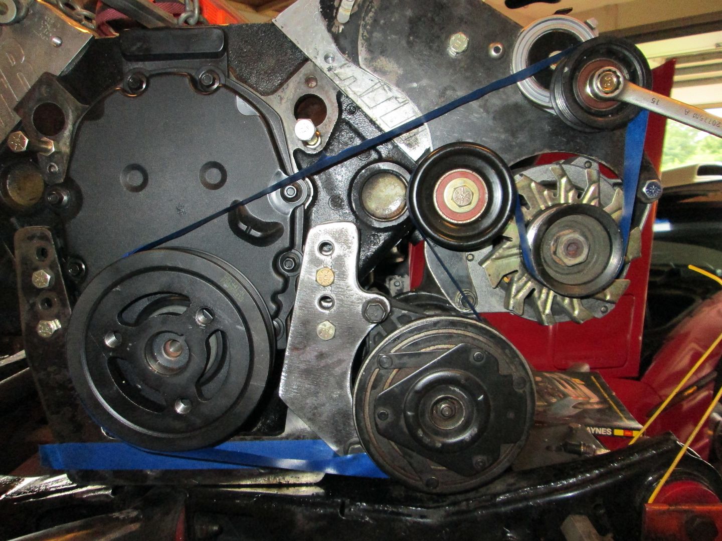
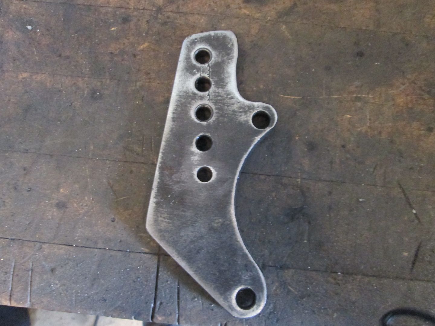
Only significant difference with this serpentine conversion vs. the first one was the Alternator bracket is steel on this car and was aluminum on the first one. The aluminum one also had a couple of extra holes and I used one of those extra holes for the idler pulley. The steel one didn't have any extra holes, so I picked a good spot for the pulley and drilled the hole.
This bolt hole needs to be countersunk:
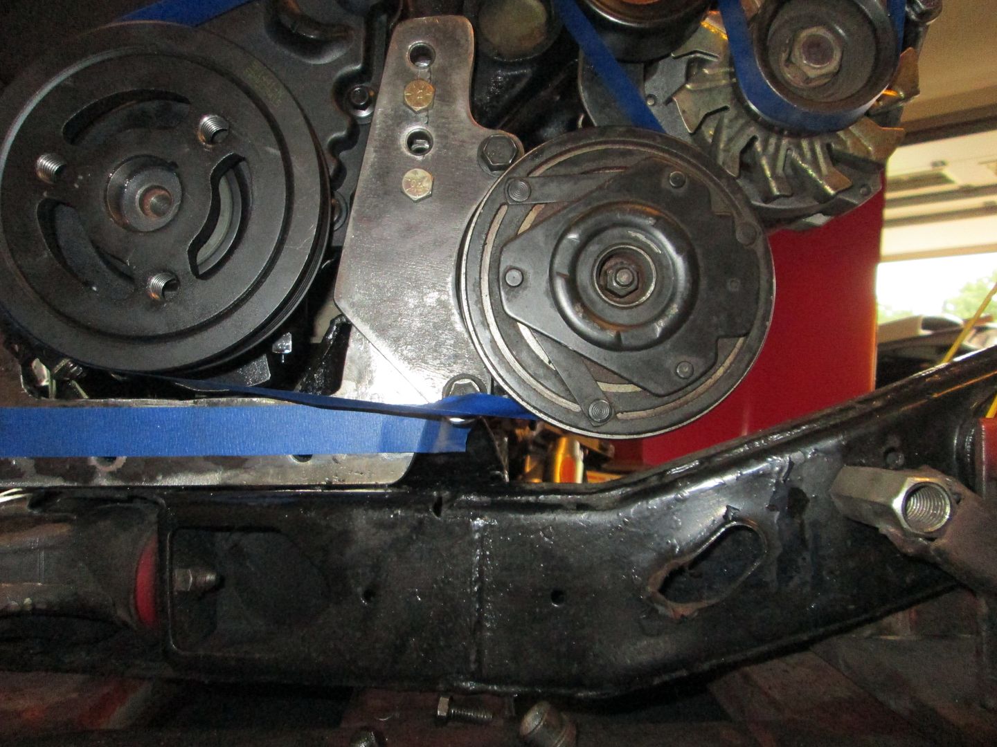
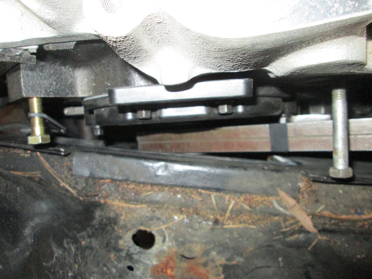
I will likely have to drill another hole in the AC bracket to allow it to be shifted up 1 bolt hole for clearance to the cradle once the Archie engine bracket is trimmed down.
I still need to machine the aluminum spacers for the AC bracket and the Alternator bracket, right now washers are stacked to the approximate (+/- 1/32") height. Once I do the test fit and confirm proper clearances, I will go back and make the rear support braces for the AC and Alternator to reduce the possibility for deflection under acceleration.
I'm also oddly happy that the bracket was steel and not aluminum. In my mind I think it'll hold up better (less bending/deflection), worth the weight difference to me.
A few more mods were done to get the engine very close to the 8" mark.
Drilled a 5th hole in the AC bracket so the compressor could be shifted upwards for clearance:
Cut 1/2" off the bottom of the Archie engine mount, welded up the remains of the original 2 mounting holes and drilled 2 new ones 3/4" in from the bottom and sides in the corners. I will likely trim off the top of the engine mount and A/C mount where the extra holes are.
Cut a new piece of angle for the backside and drilled 1 hole in it. I will drill the other side once all the mounts have been fabbed and tacked into place.
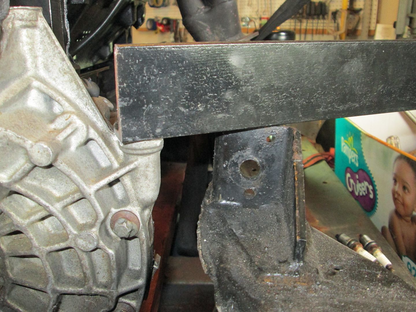
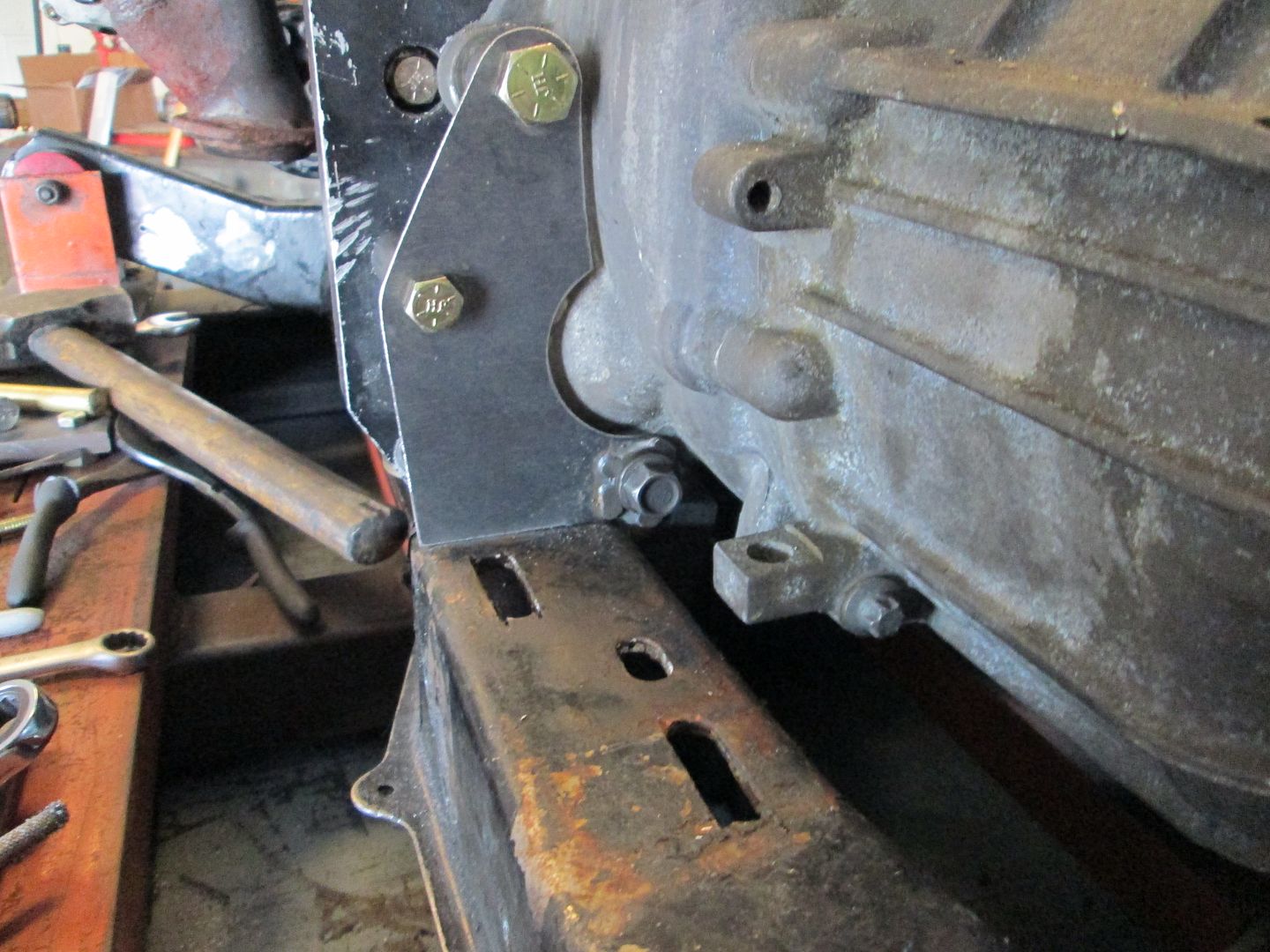
I fabbed up some temp support mounts on the transmission side so the drivetrain can sit level on the cradle and still be able to be shifted front/back and side to side during the test fit. Once the test fit is done and optimal engine placement is determined, I will fab up the real transmission mounts.
Very good chance the drivetrain and cradle will be back in the car on Sunday for the test fit to determine optimal engine placement.
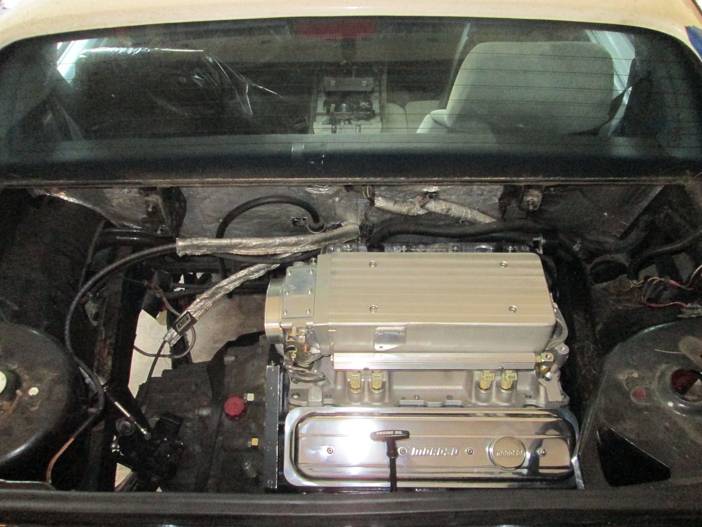
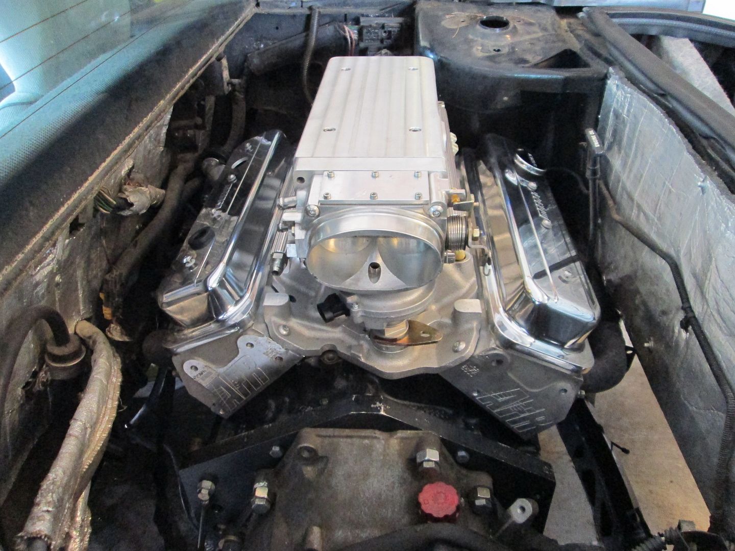
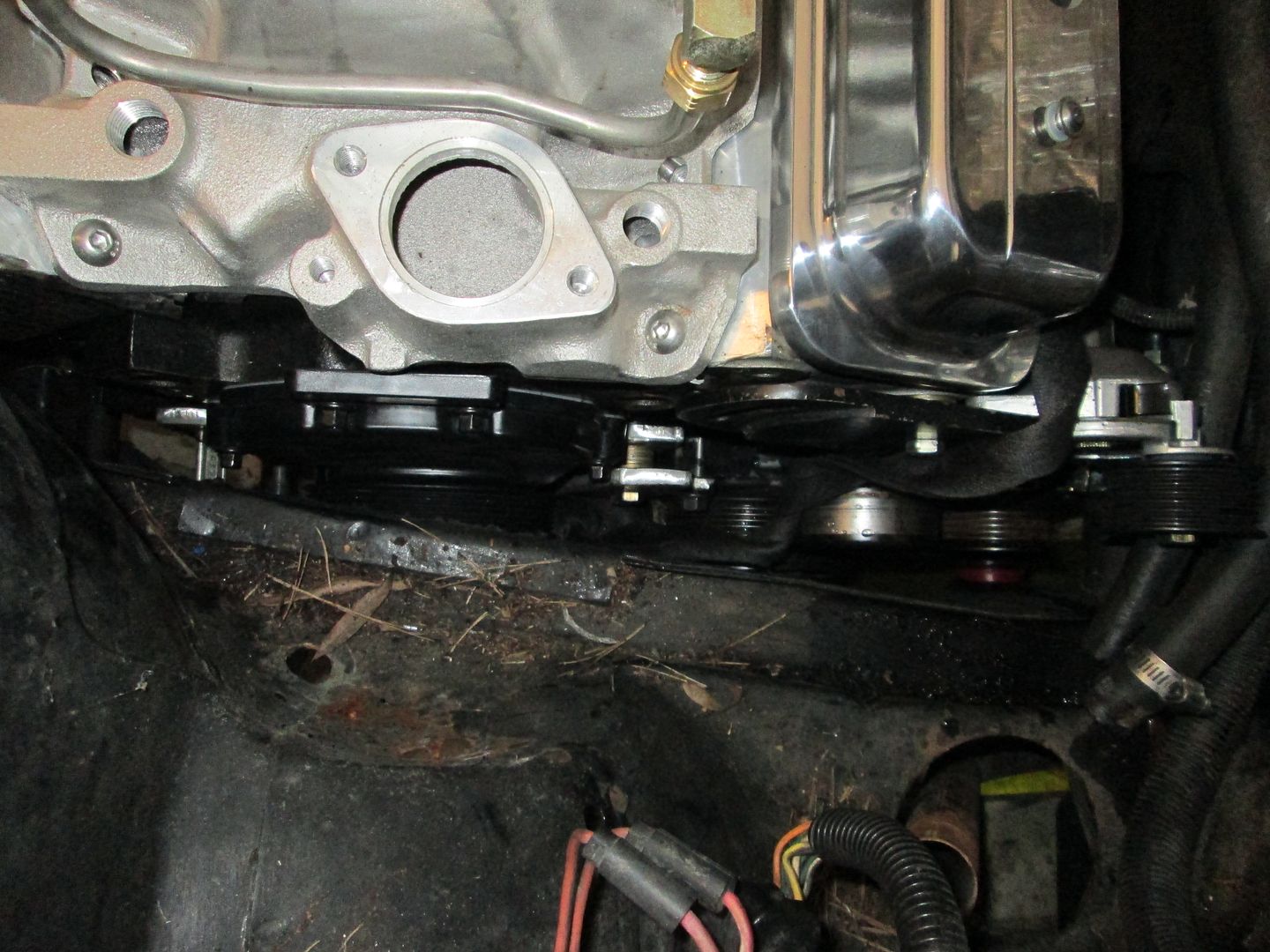
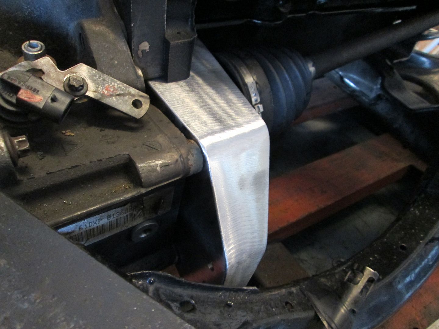
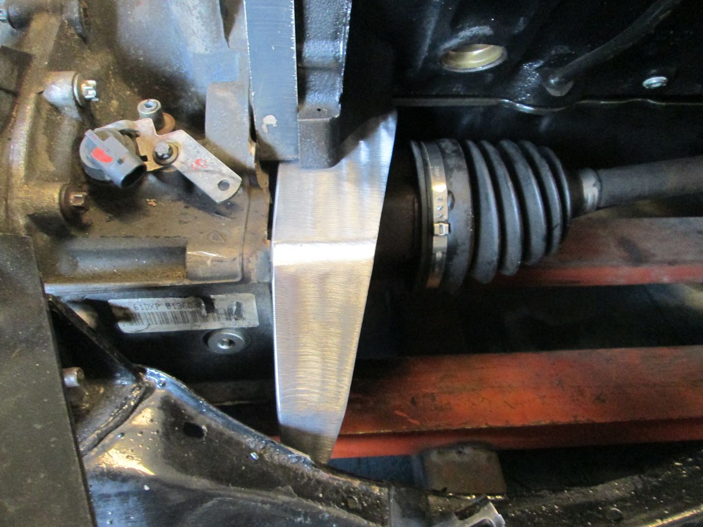
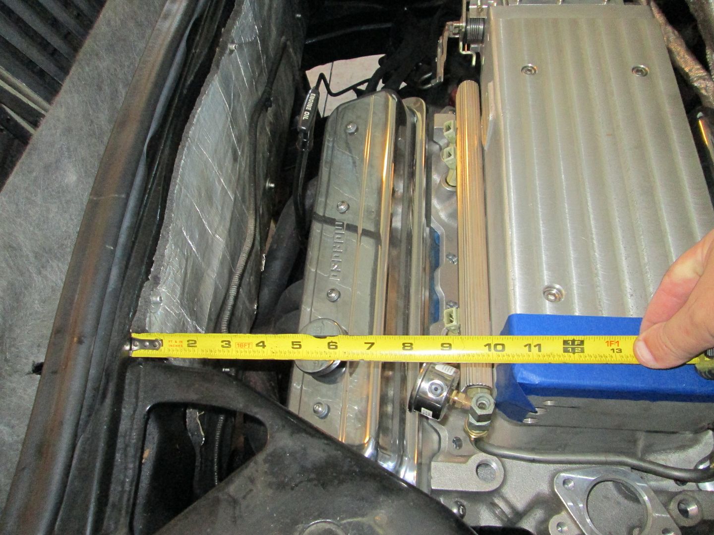
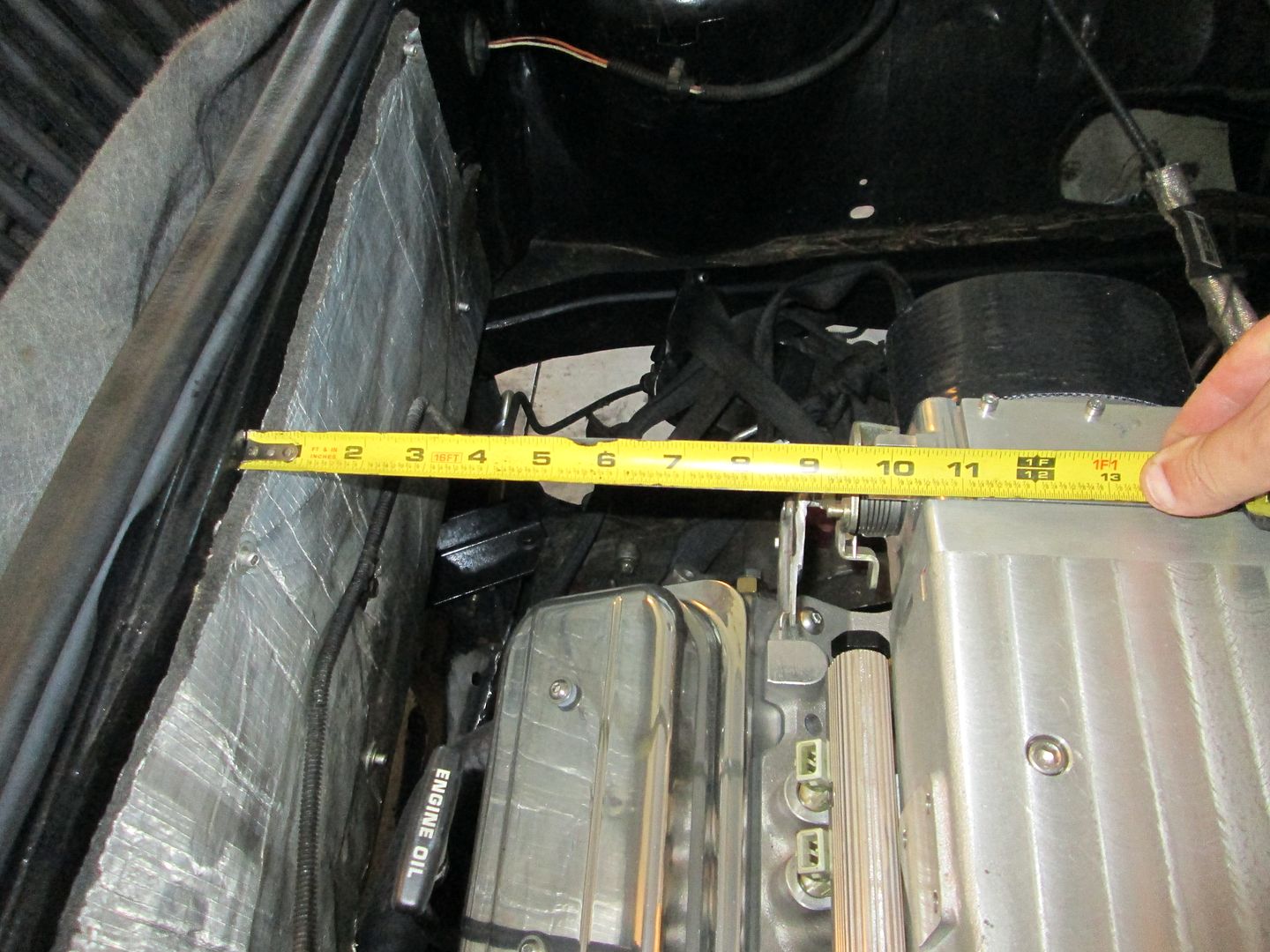
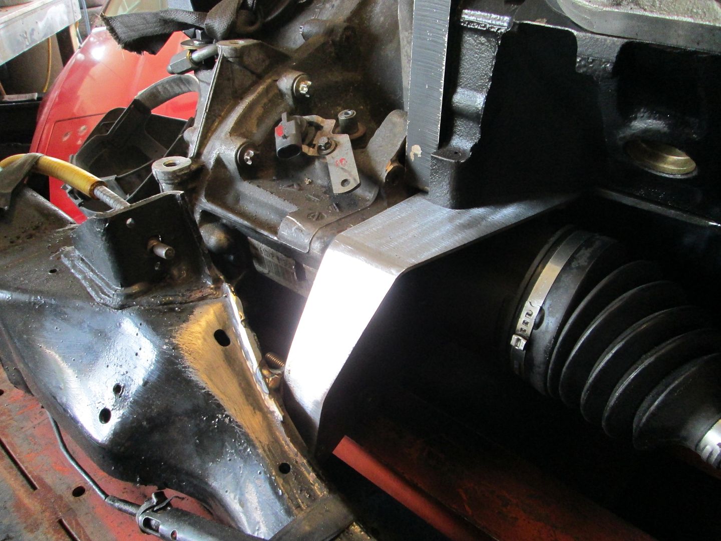
Drivetrain was put back in for a test fit today. Here are a couple of pictures of what the engine will look like with its new valve covers.
I moved the engine around some, but there isn't much available room with it in its lowered state. One of the potential interference issues is the transmission with the lower A-arm at full compression. I will install the strut w/o a spring and cycle the suspension to full compression to see if the lower a-arm needs a slight notch.
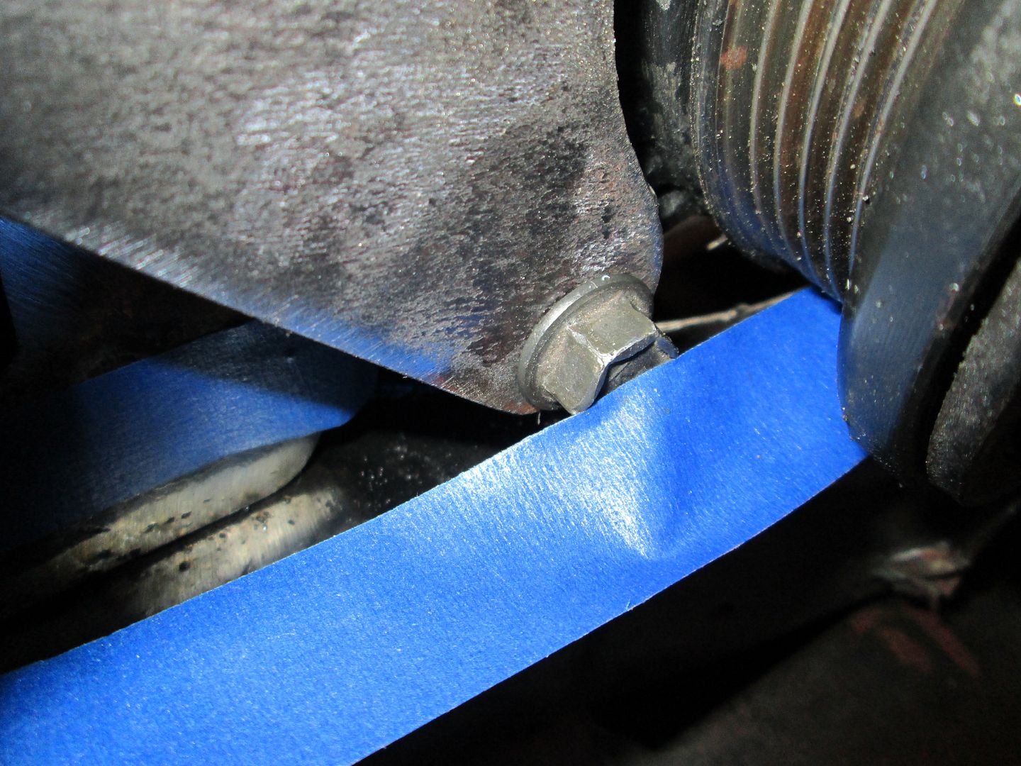
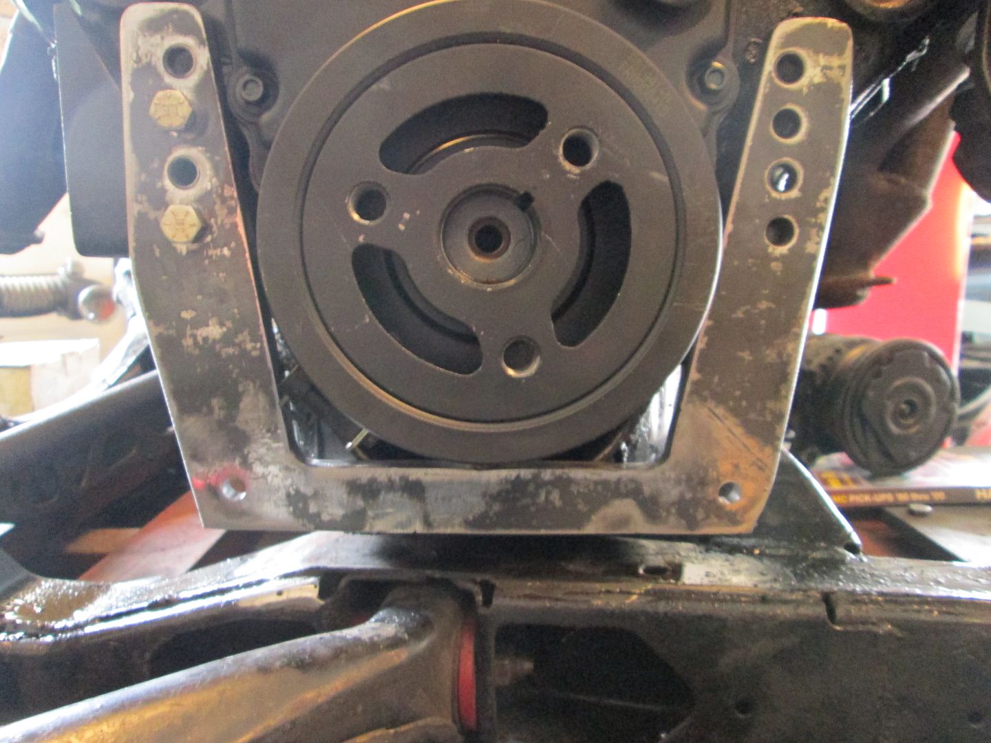
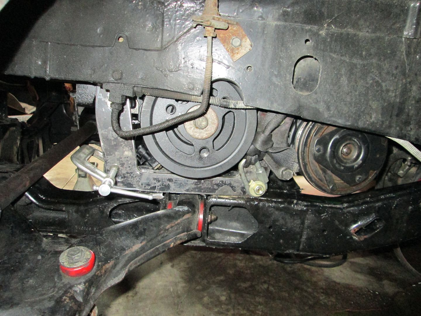
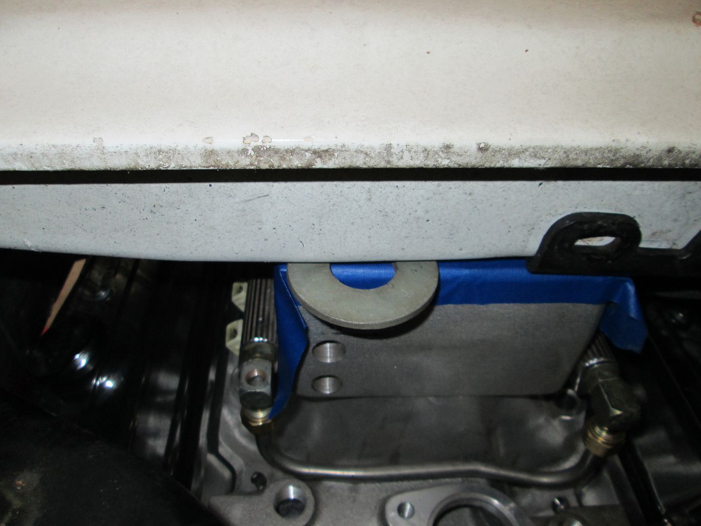
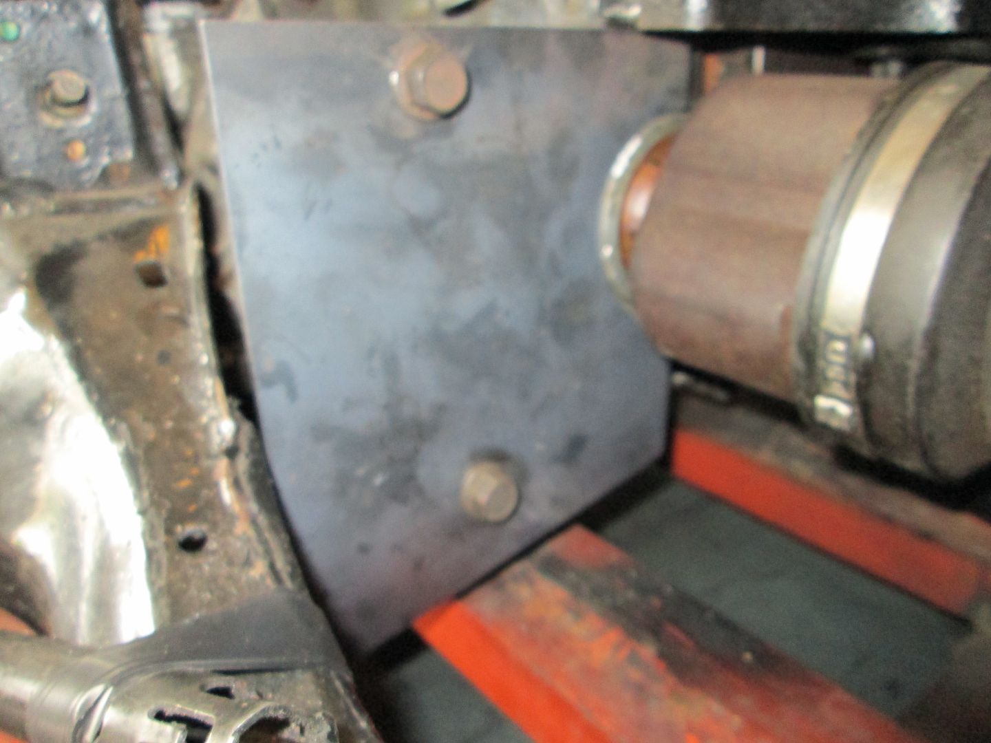
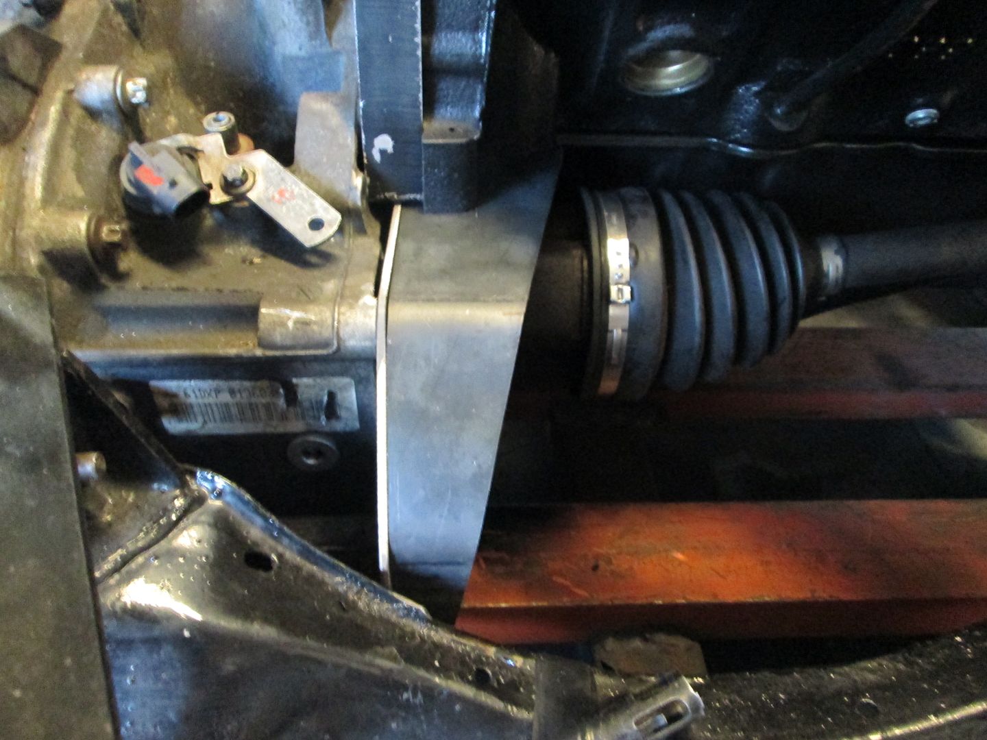
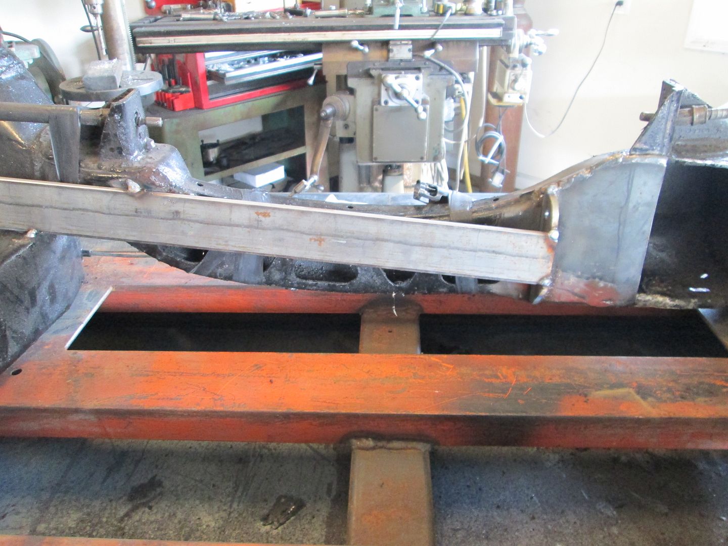
The previous installation had the balancer bolt pretty much in the center of the circular notch in the frame rail, so this picture shows how much lower the drivetrain is now (as well as how much further to the rear it had to go for alternator clearance to the double firewall panel (in the raised position, the alternator can be over the top of the double firewall panel.
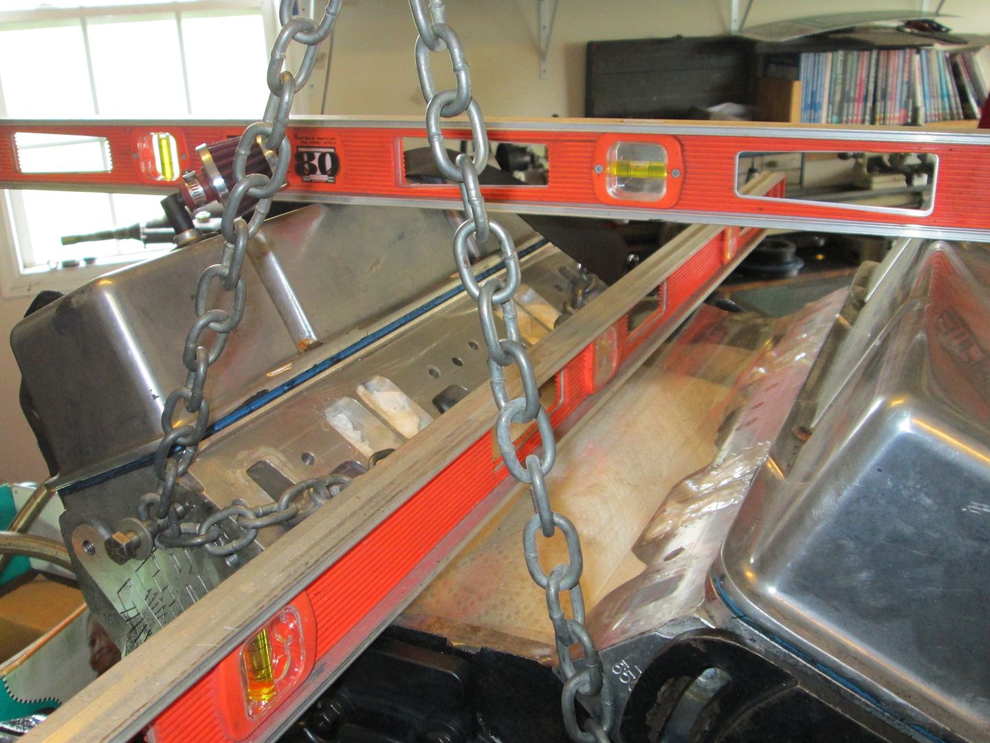
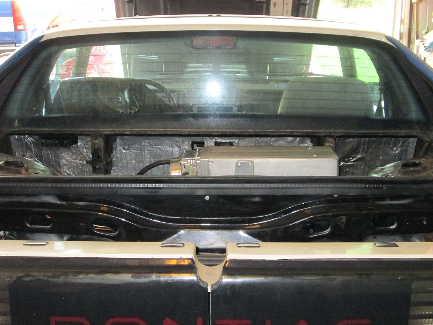
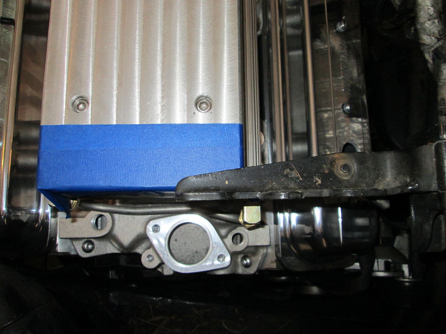
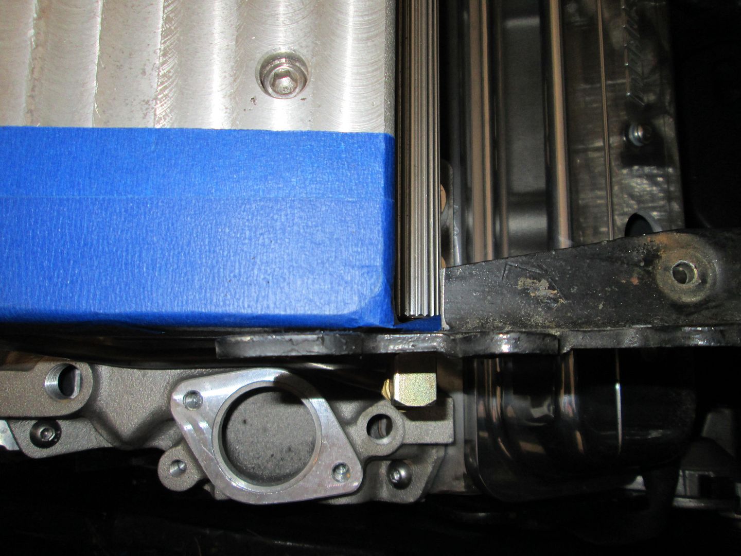
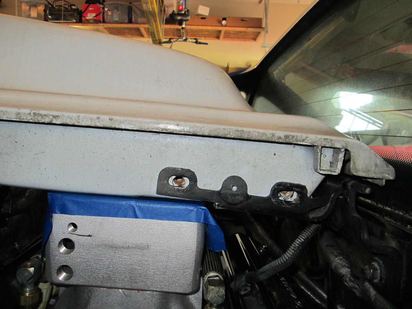
All the lowering was to try to get the intake under the support rail of the GT decklid. Here is a shot with only the hinge. This will need to be notched:
I slid the fastback decklid into place, but it is resting on the hinge which is resting on the intake. Notice the black sharpie mark on the intake, that was where the bottom of the decklid used to come:
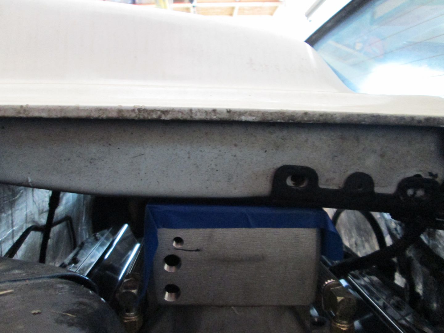
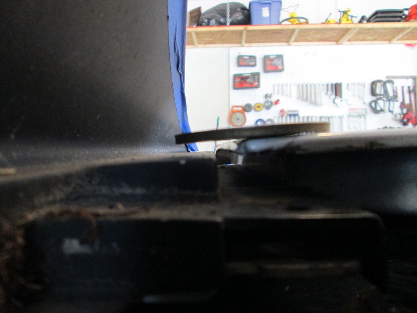
Here I slid a washer under the decklid checking for available room:
Notched the hinge:
Decklid back on. Still need about 1/4" more clearance. So I will eventually have to trim the decklid support some, but it will be very minor.
There are a few more things I want to check and then it will come back out to start fabbing the transmission mounts and filling in the notched sections of the cradle.
Thank you for the update and all the pictures. It's neat that in retrospect we can see things that you thought of to start with. For example, it appears you must have marked the decklid -to-intake relation when you had first taken off my old intake and set on the new one to see where things sat before you pulled the engine. I know I wouldn't have thought of that.
Last summer I drained and refilled the transmission fluid, so I hope I'm correctly remembering this -- the drain plug for that transmission used to sit parallel to the cradle, there was just enough room to slide a ratchet up there to loosen it, then unscrewing it by hand. With the repositioning of everything, I'm guessing that plug is now going to be beneath the cradle? Or was it parallel to something else?
Originally posted by Trinten: It's neat that in retrospect we can see things that you thought of to start with. For example, it appears you must have marked the decklid -to-intake relation when you had first taken off my old intake and set on the new one to see where things sat before you pulled the engine.
Yes, preplanning, thinking through the mods, and getting some reference measurements when able results in fewer test fits. Nothing like having to put the drivetrain back in for 1 measurement you overlooked, or having to pull it back out because it doesn't fit... Its one of those things you learn to do after you have done several swaps.
quote
Originally posted by Trinten: the drain plug for that transmission used to sit parallel to the cradle, there was just enough room to slide a ratchet up there to loosen it, then unscrewing it by hand. With the repositioning of everything, I'm guessing that plug is now going to be beneath the cradle? Or was it parallel to something else?
Yeah, the drain plug used to be slightly above the top of the cradle rail, but now it is about 1" above the bottom of the cradle. There is about 1 1/2" between the plug and the differential so you will likely need to use an allen wrench to remove the drain plug.
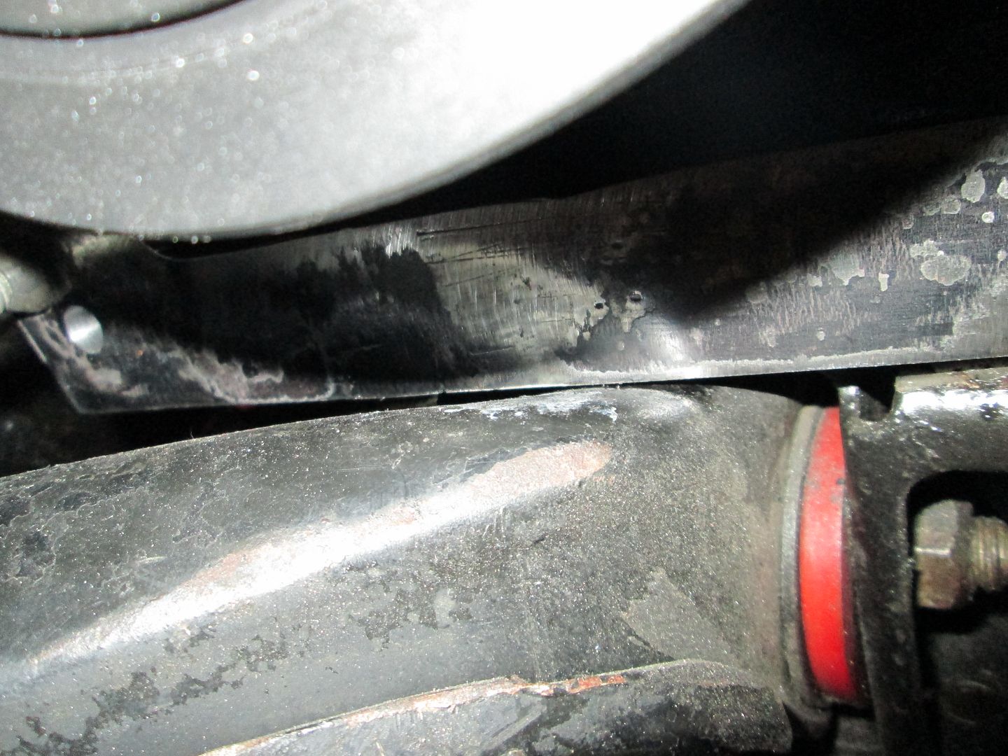
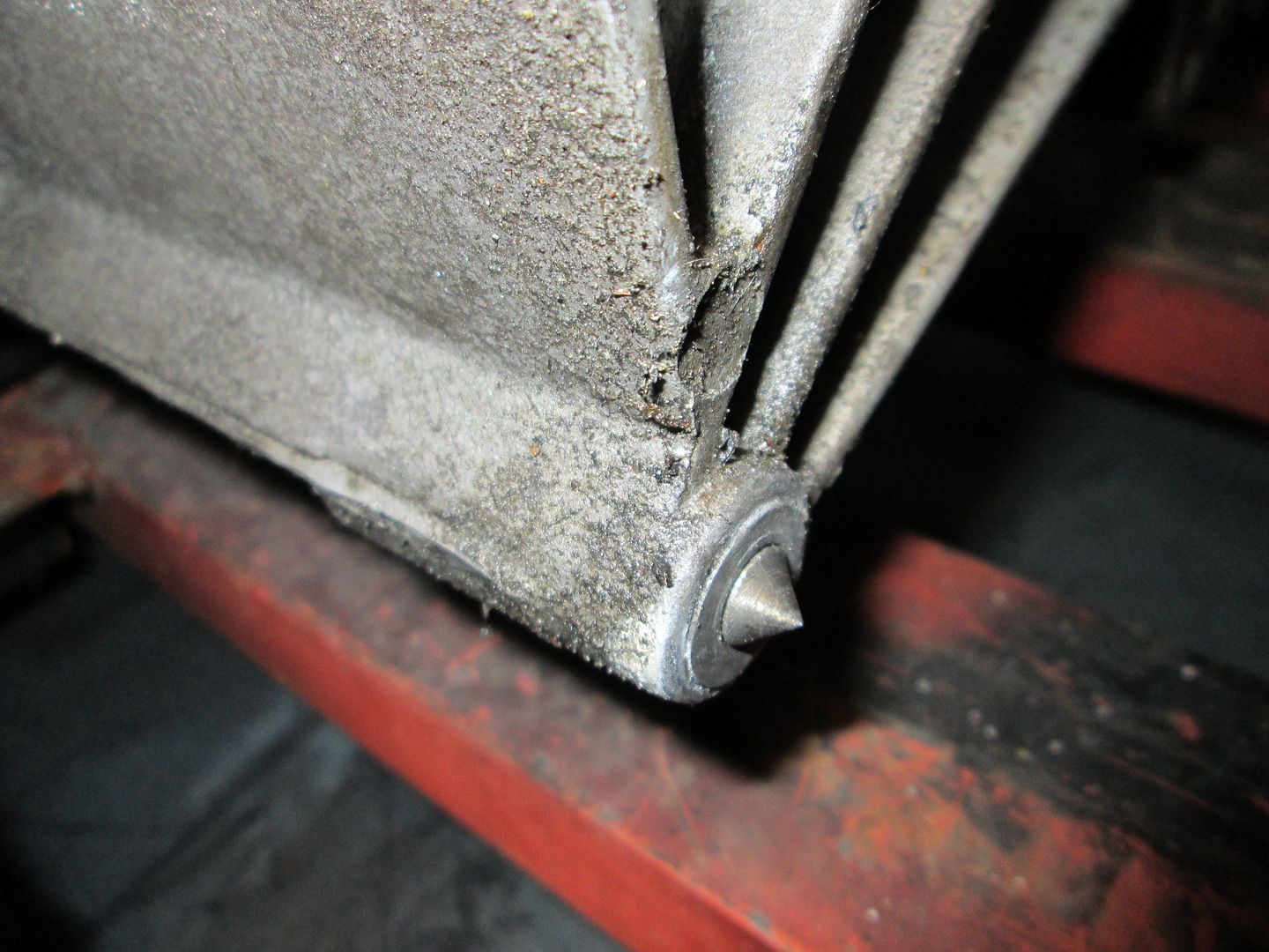
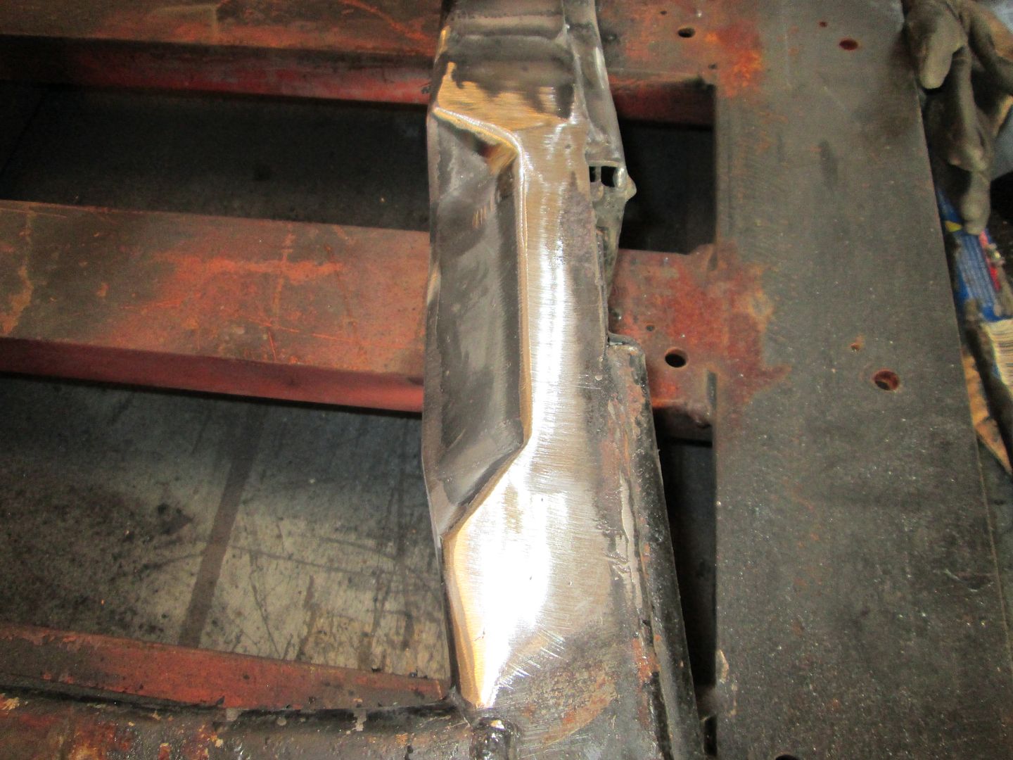
I forgot to share the picture of the bottom of the oil pan. Here is before:
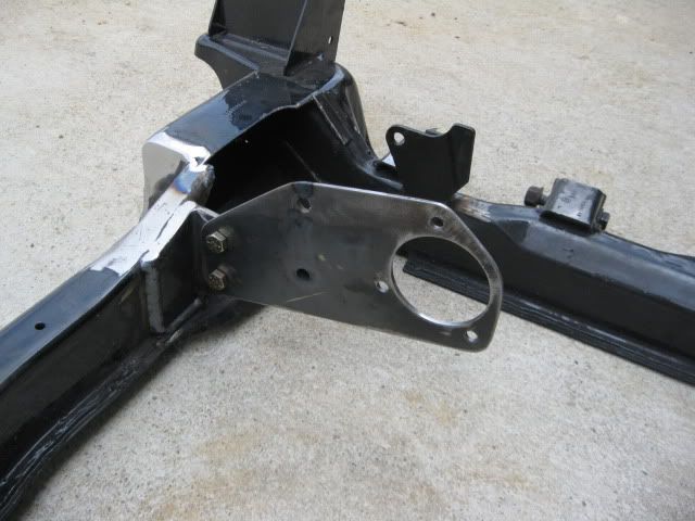
Originally posted by CowsPatoot: One question though...
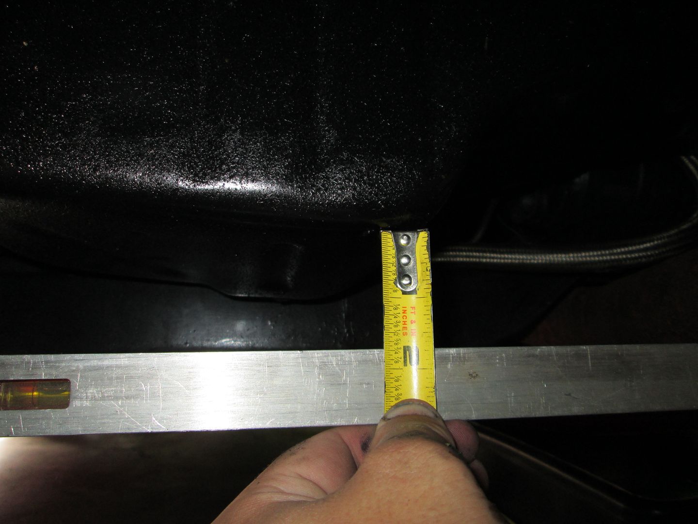
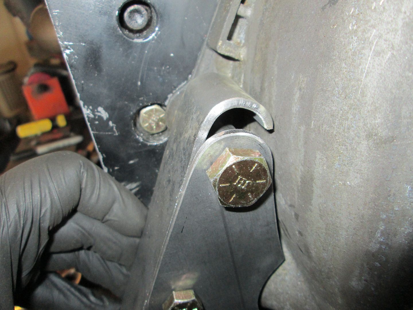
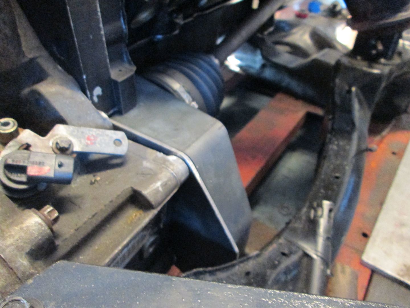
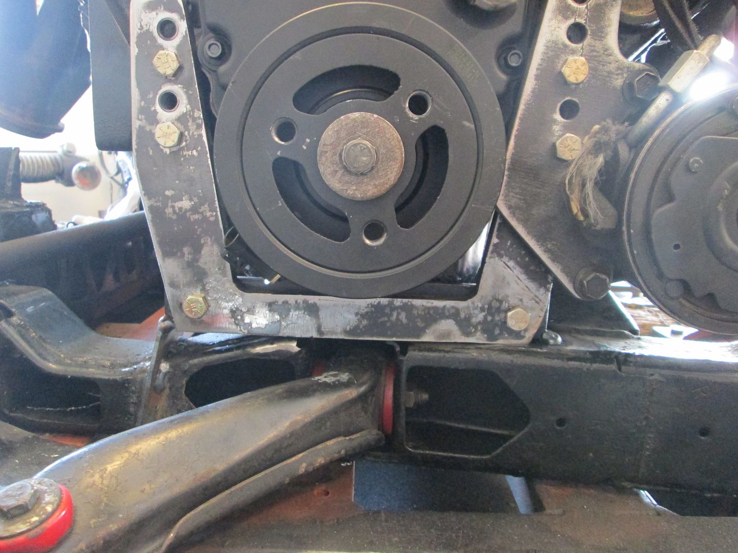
Is the serpentine belt going to clear the circled section of the frame? Hard to see from these angles, but looks like it could be close.
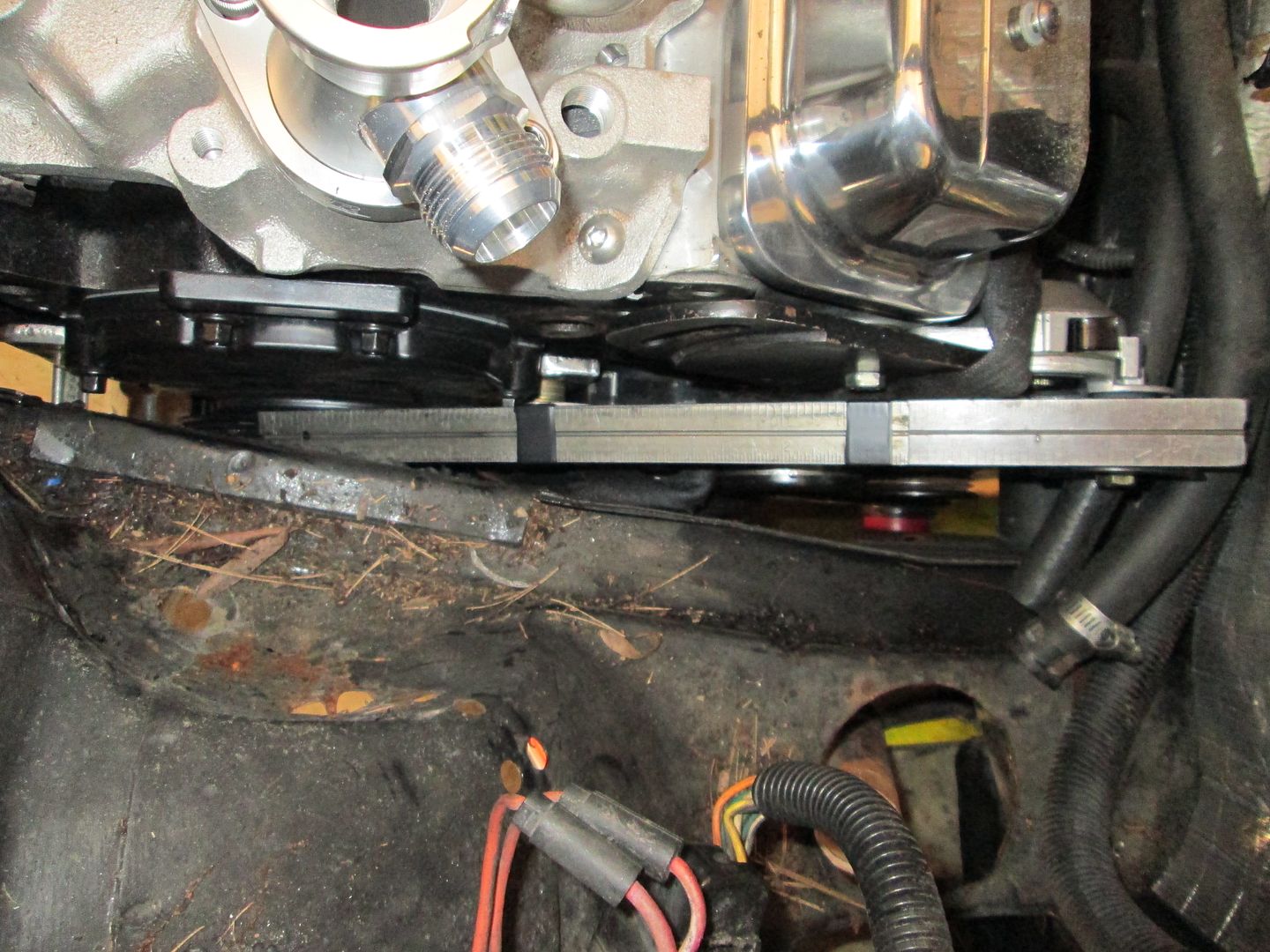
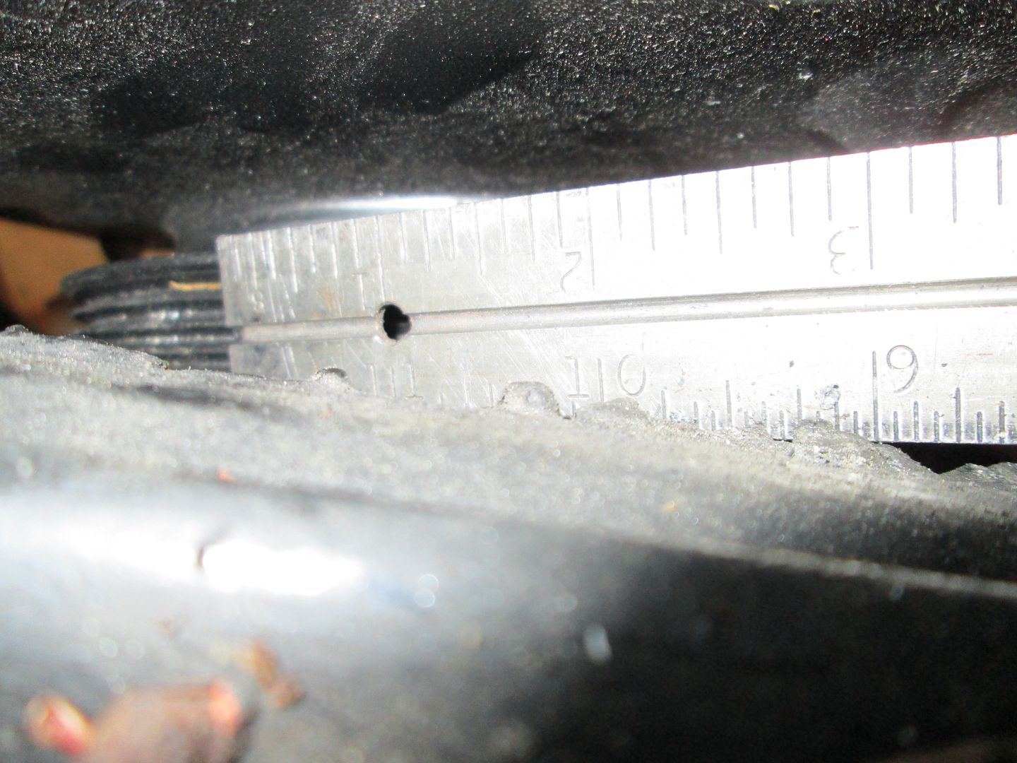
That is one of the many items I am checking with this test fit. I am planning to minimize the notch from its current state, so if I have to raise it slightly for belt clearance I can do that to. Right now the tensioner is unloaded and at its highest point. So I will place a straight edge on the pulleys and scribe the frame rail.
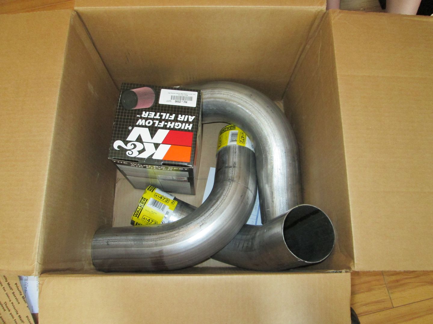
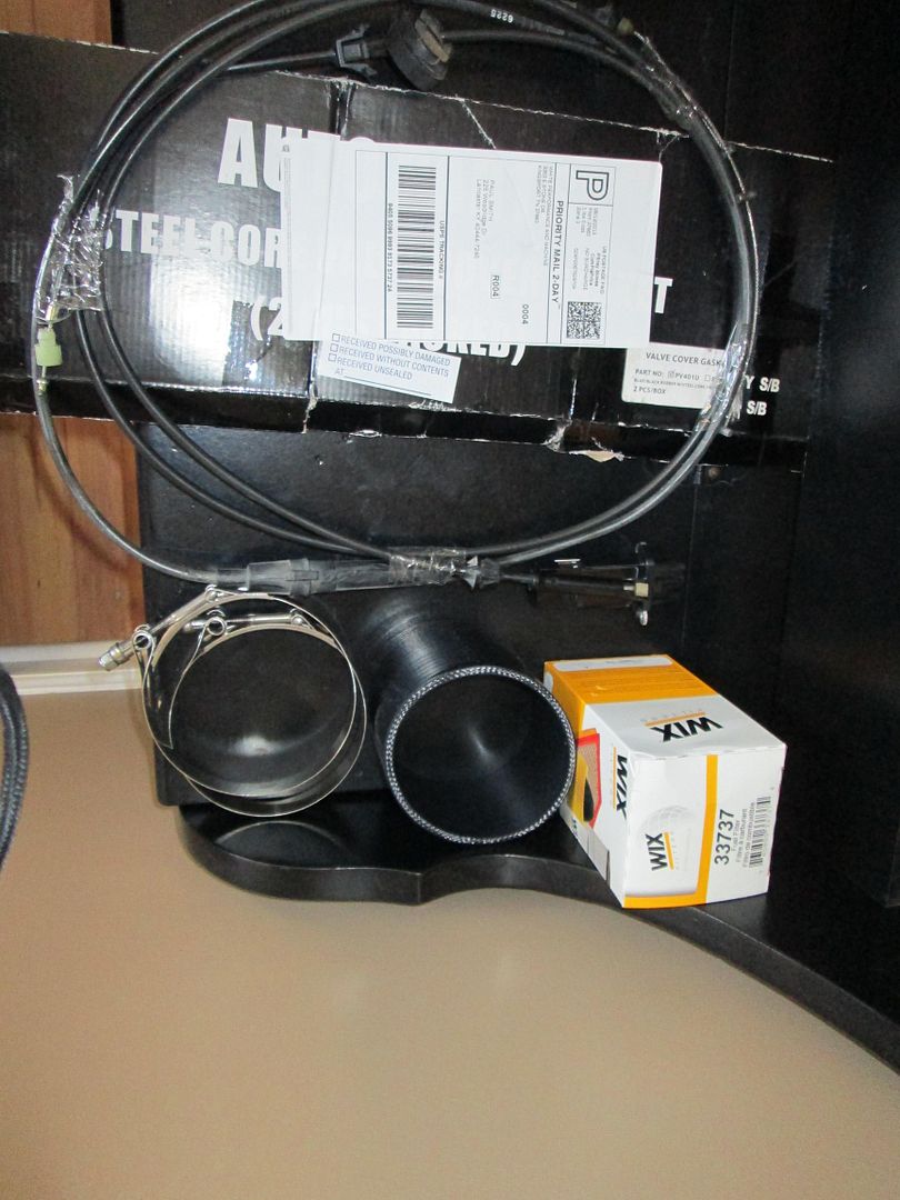
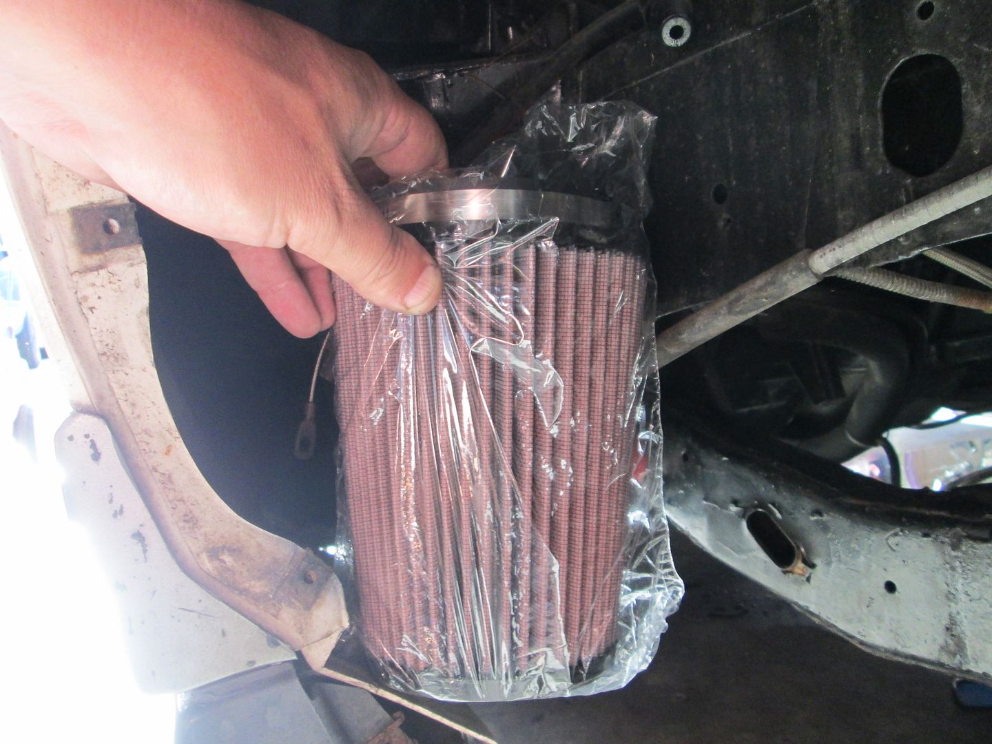
Here are the main parts for the 4" cold air intake:
The silicone coupler, T bolt clamps, 88 4cyl throttle cable, fuel filter, and valve cover gaskets:
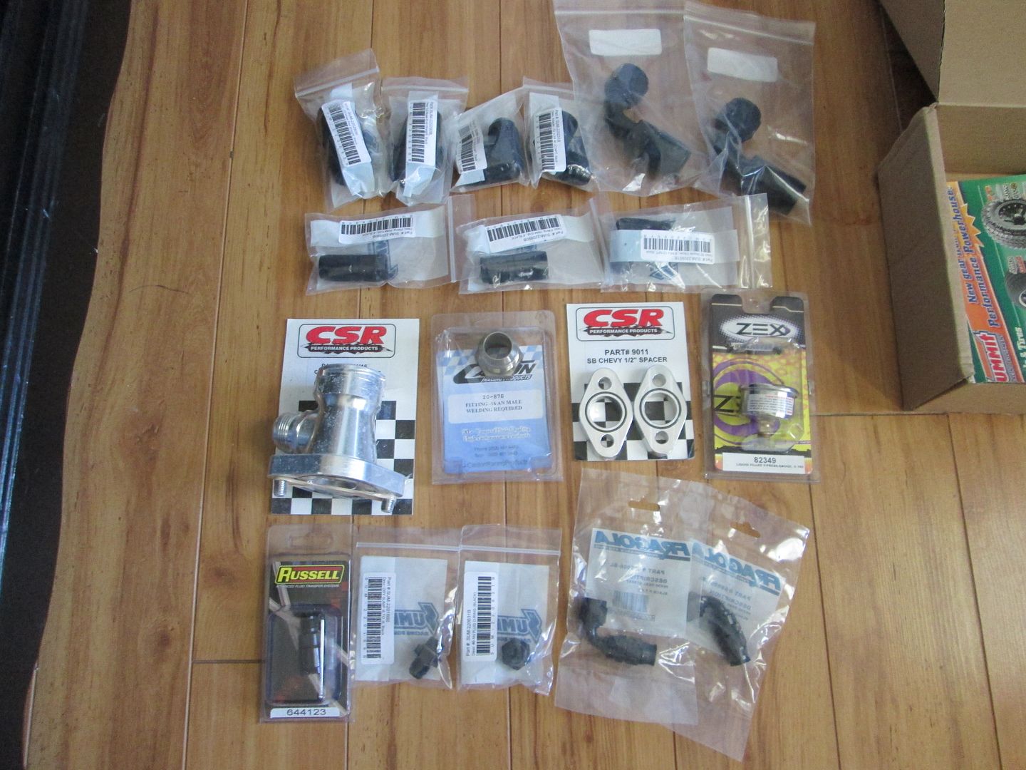
Many of the AN parts - a few are still in route:
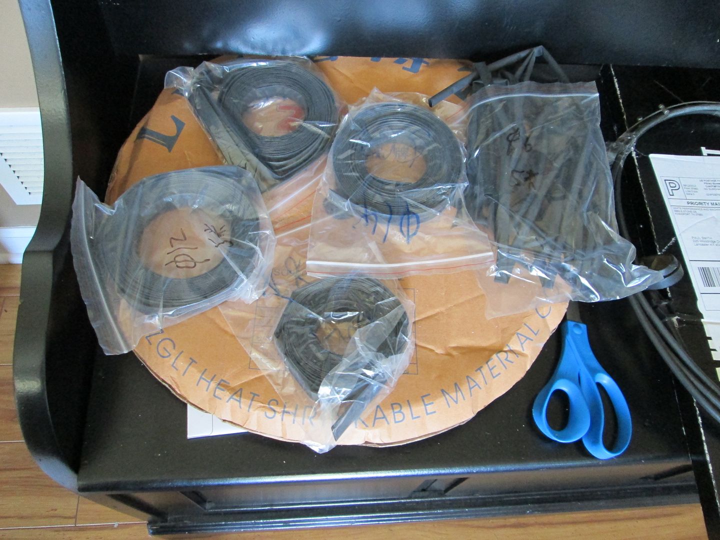
Heat shrink for the harness - this stuff came all the way from China!
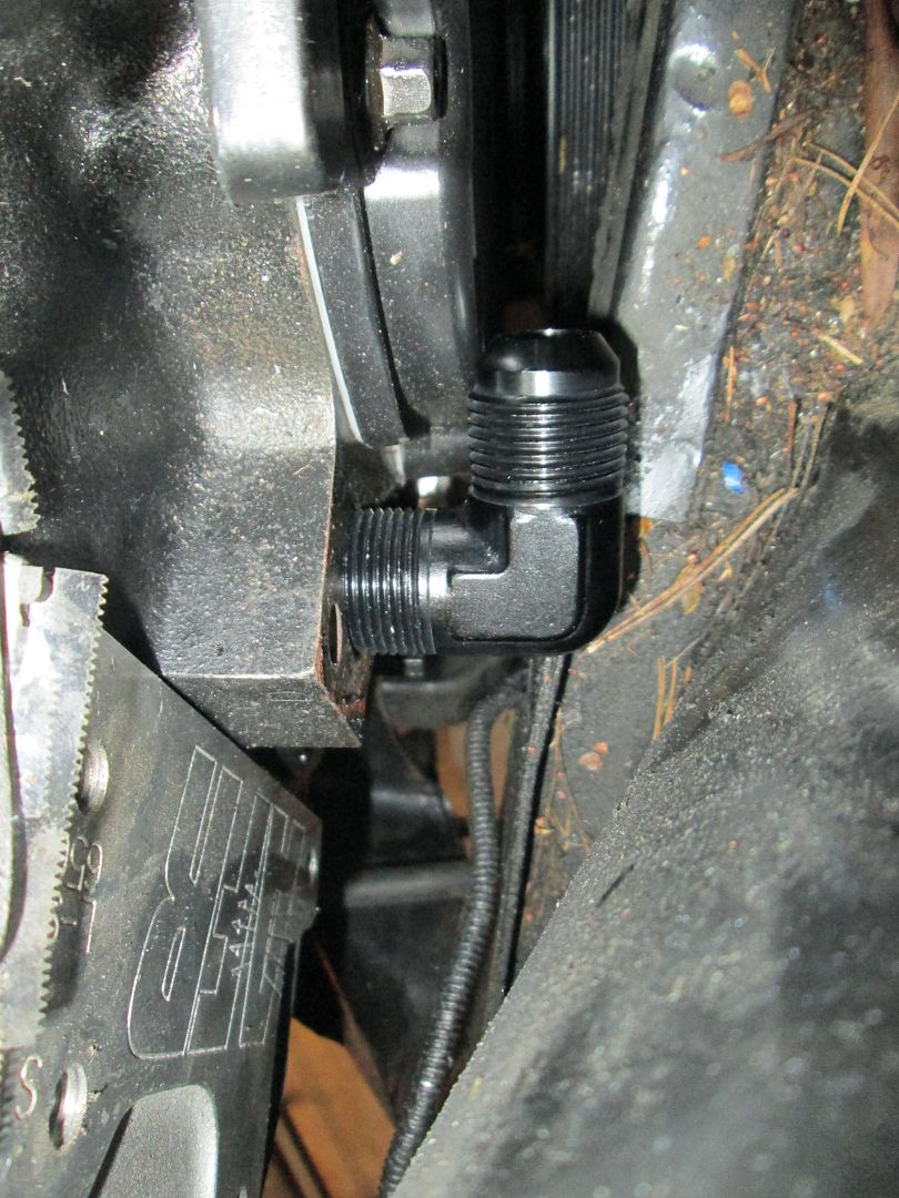
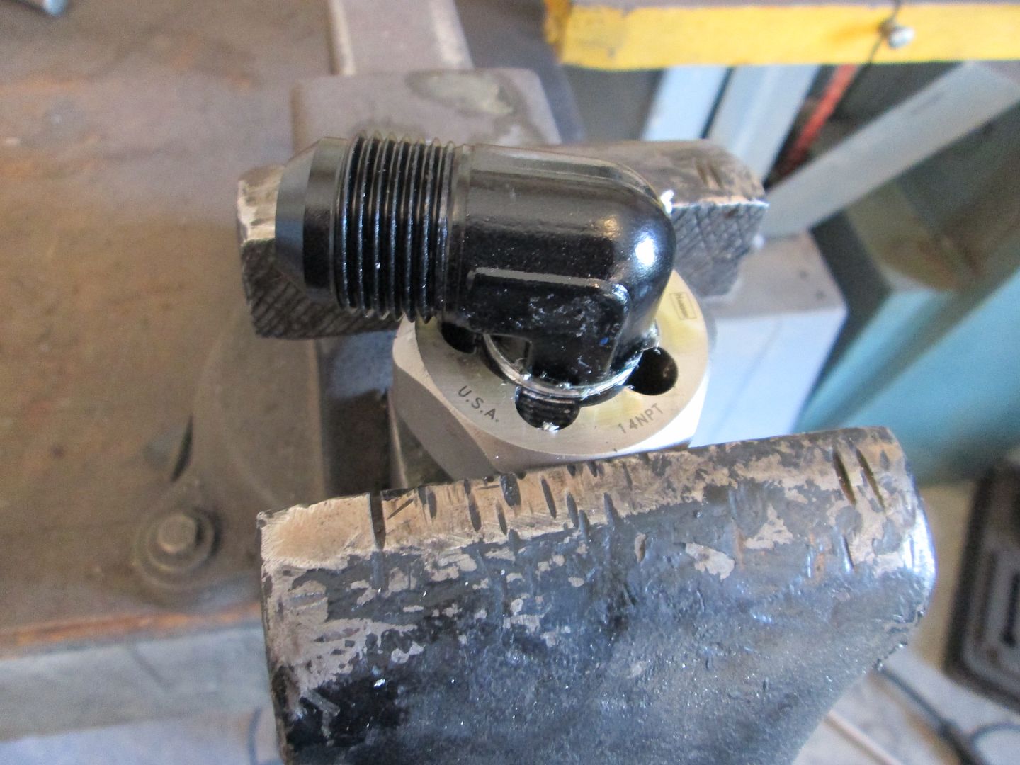
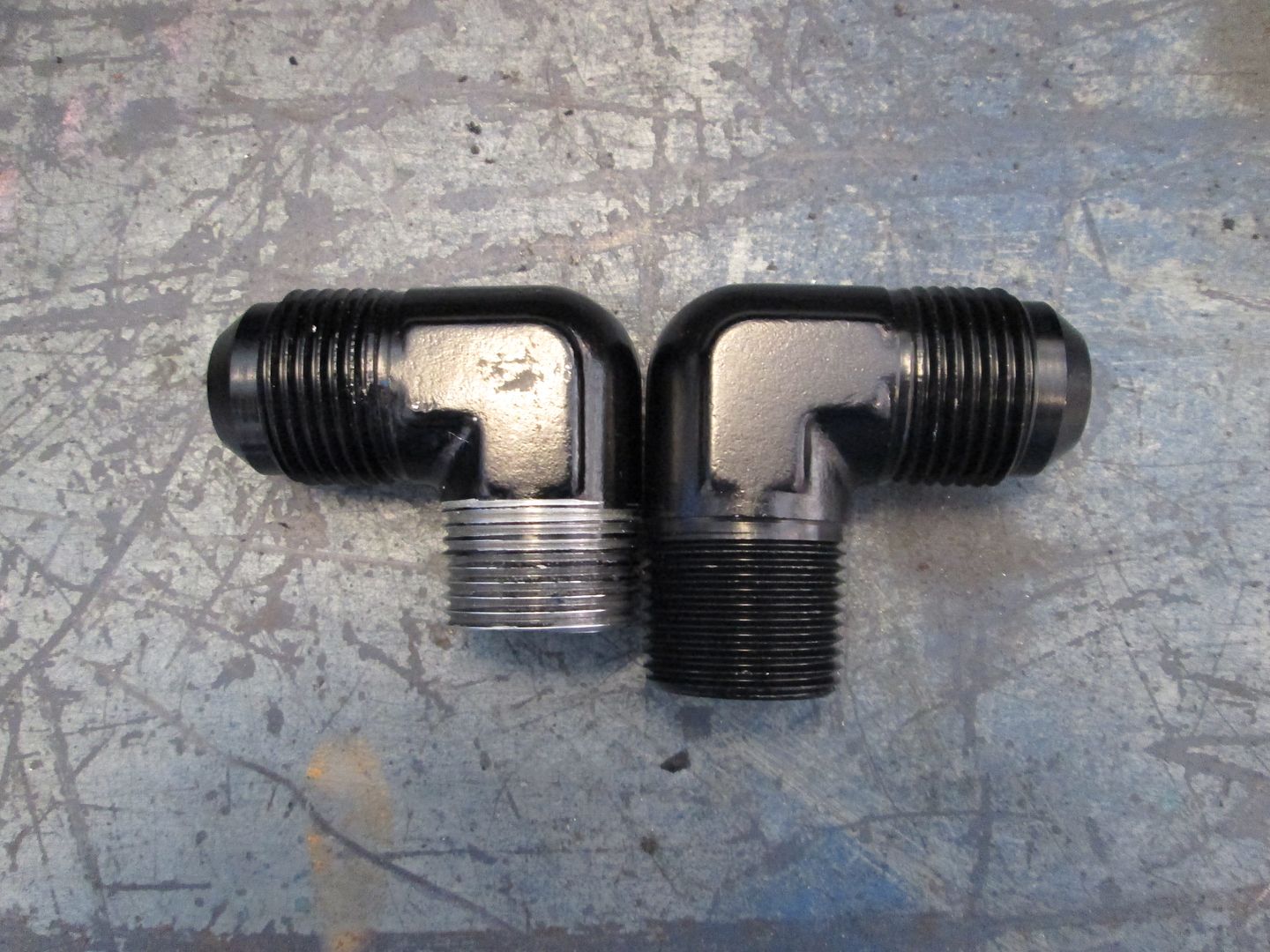
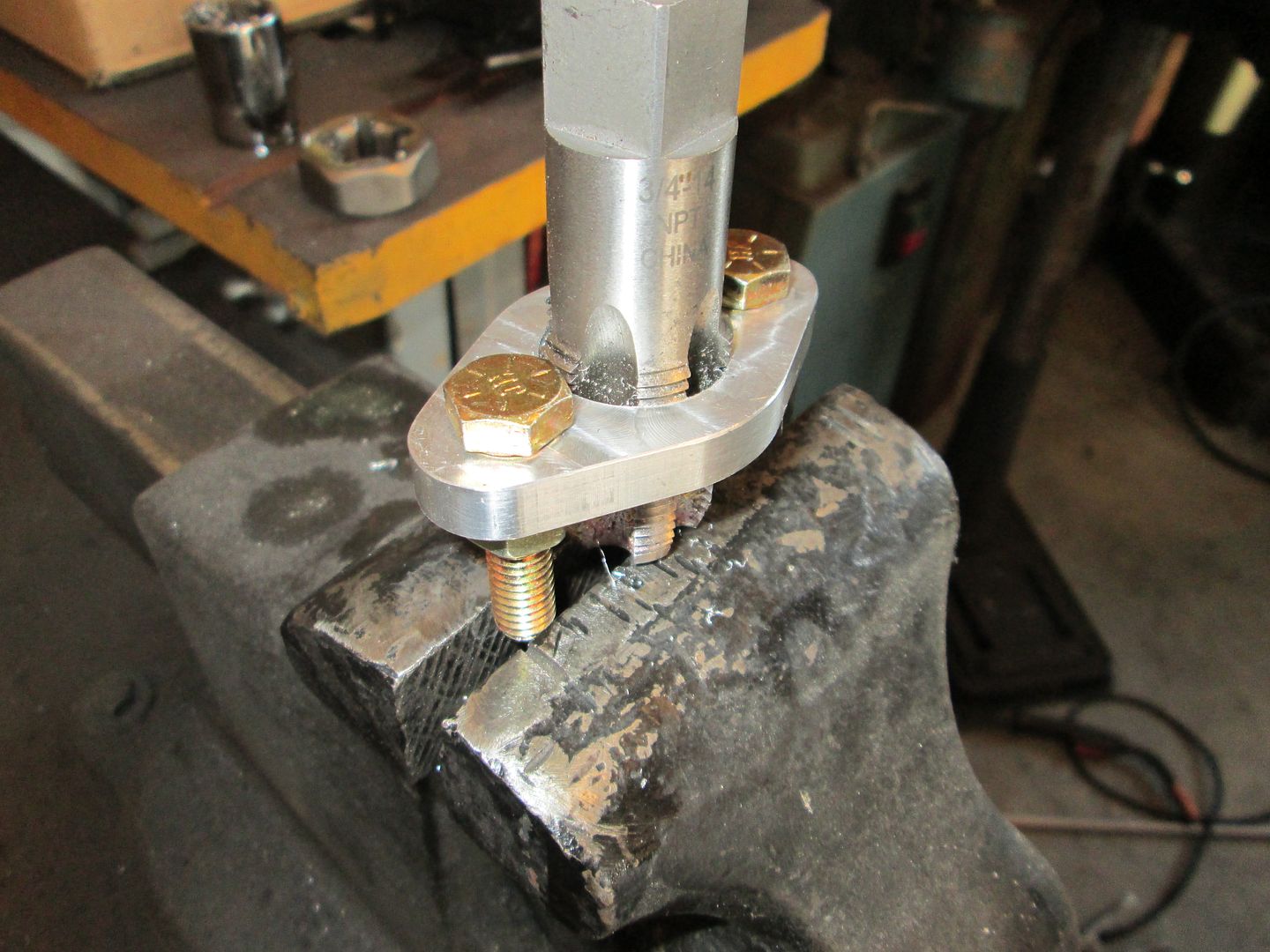
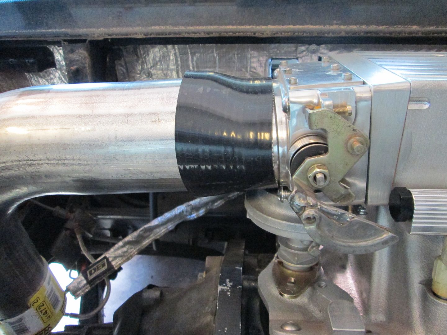
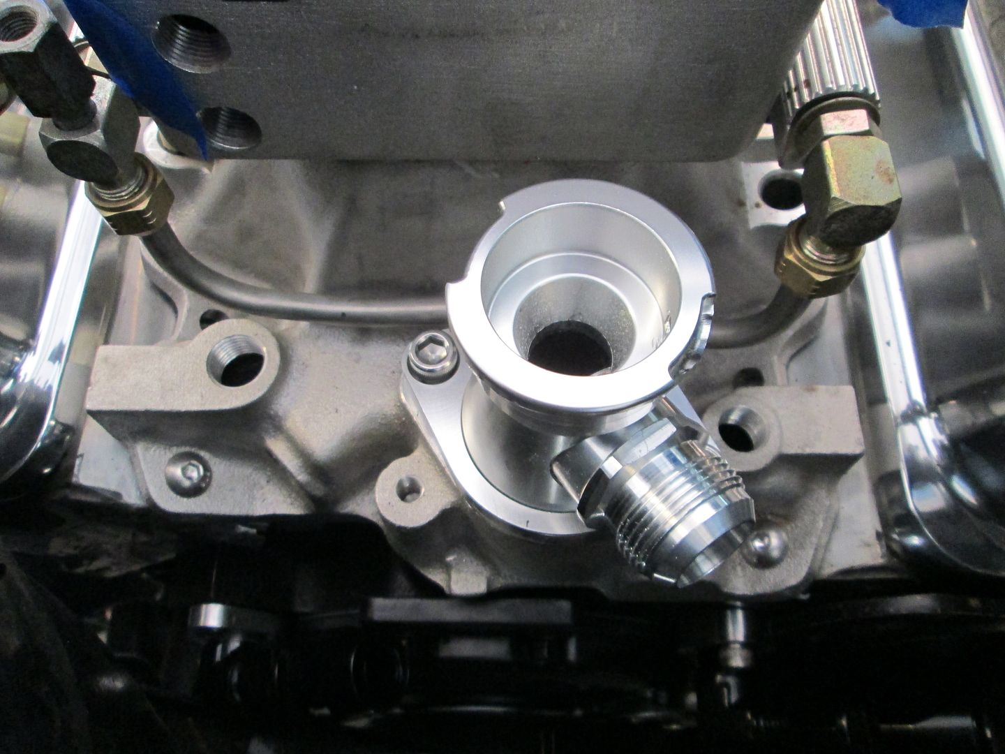
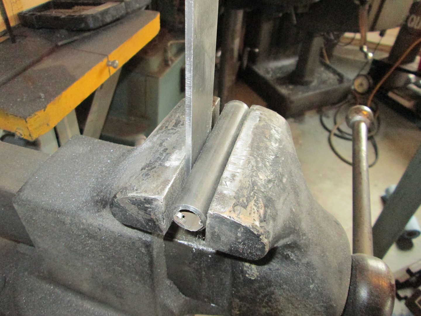
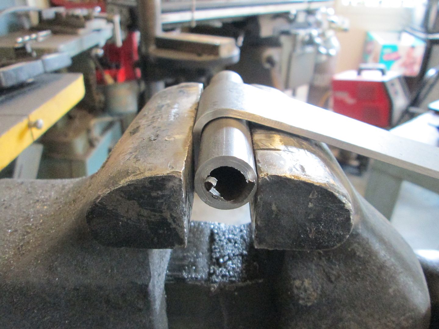
Then I went to work on the mods needed for the coolant hoses at the block. Here is one of the fittings and it clearly needs to be shorter if it is to clear the frame rail:
So I trim the threaded end down and then use a pipe die to extend the threads on the fitting: Its getting closer, just needs to be a little shorter:
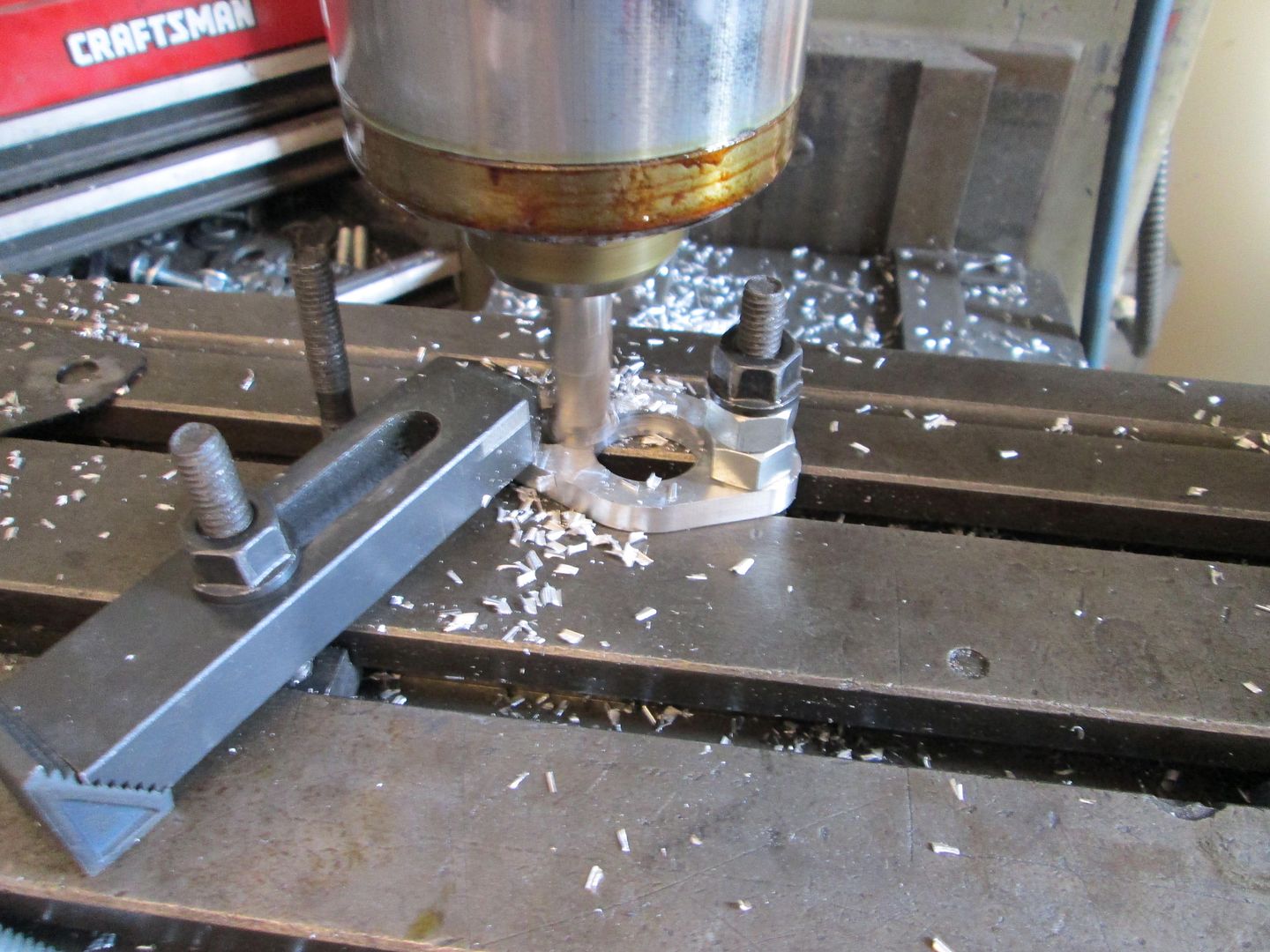
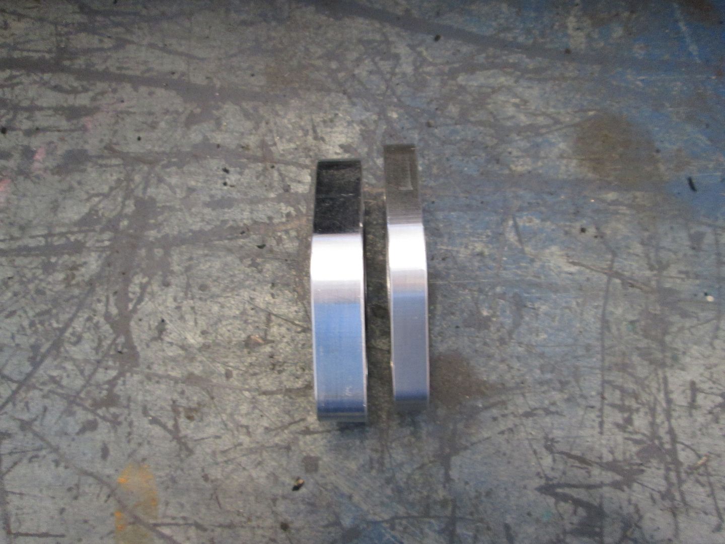
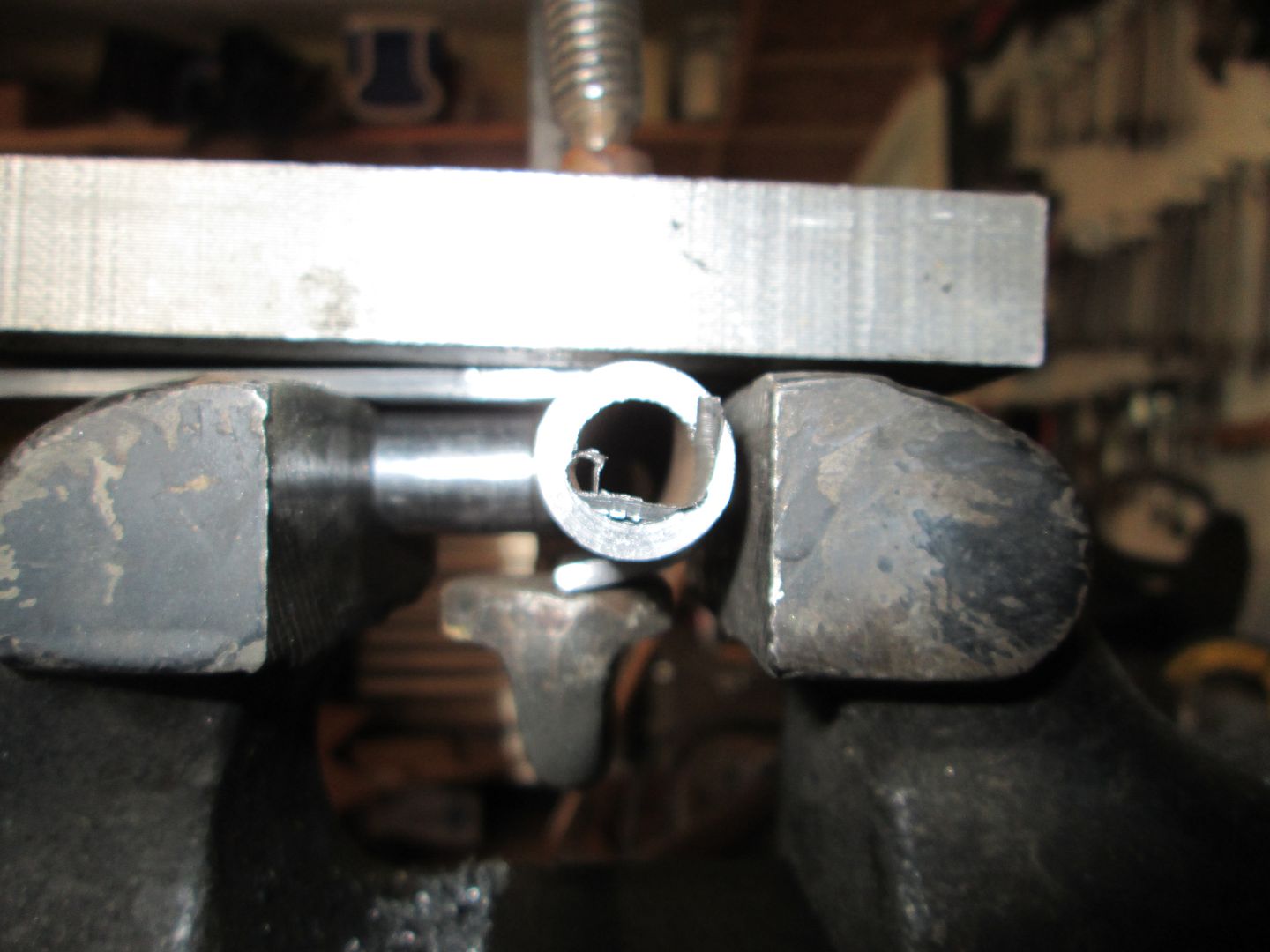
The fitting above will thread into some aluminum plates (water pump spacers), but one of them also needs modified to make it much thinner. So it spends some time on the mill:
Comparison between the two now:
Tap the center hole for the fitting:
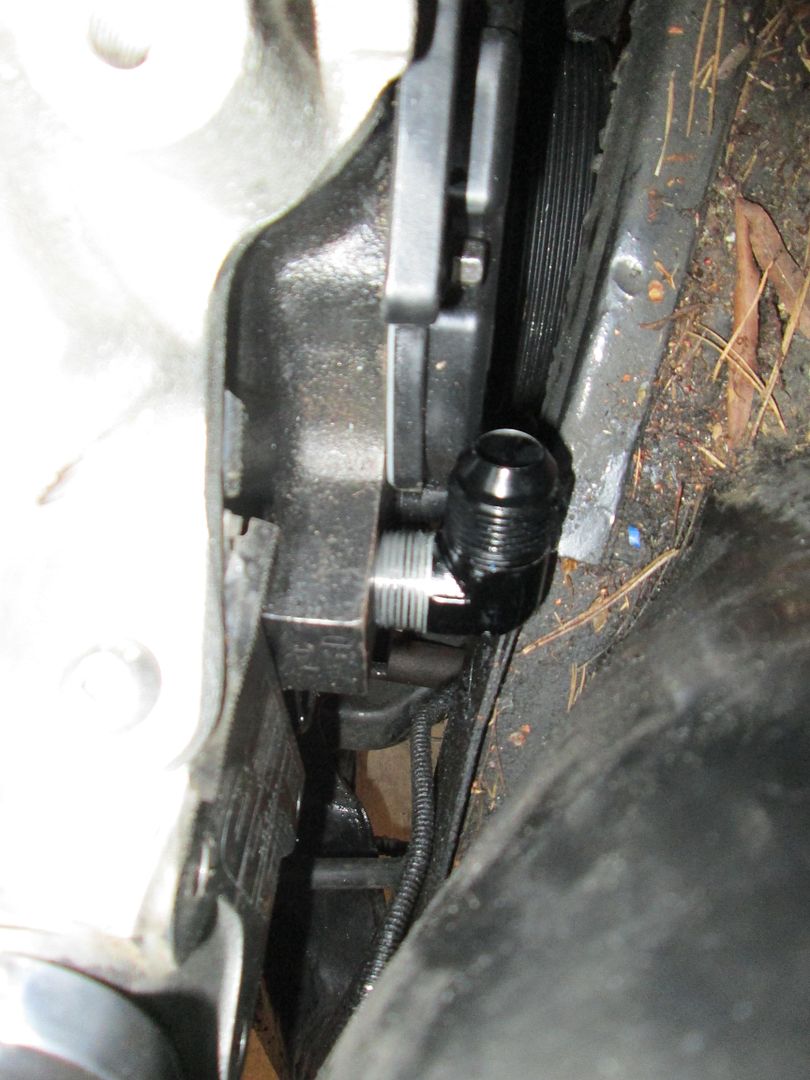
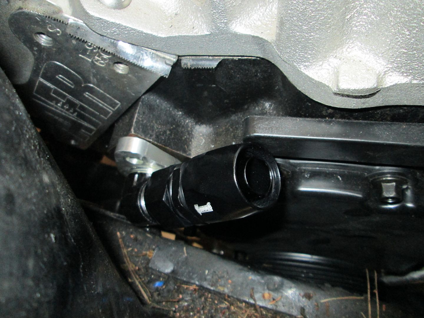
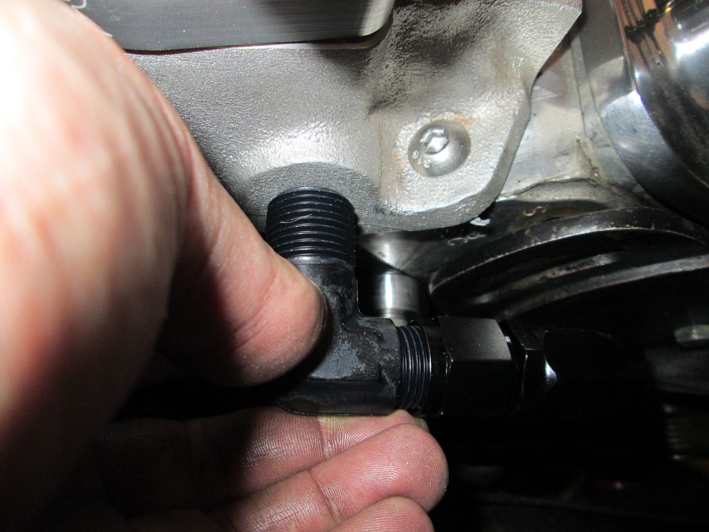
Here the modified fitting is sitting in place with the hose end attached:
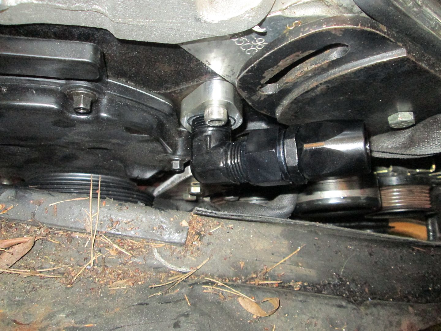
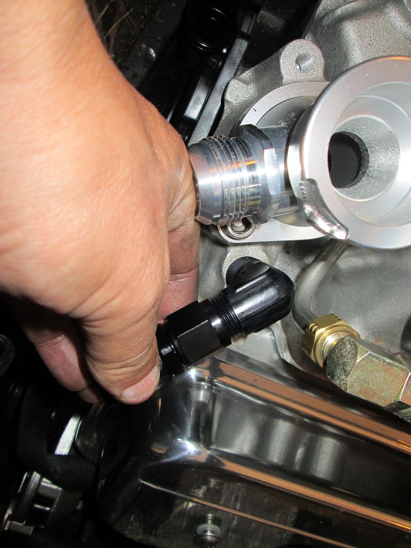
The other one fits with only having to thread the plate:
Here is a mockup of the cold air intake. I will likely oval the tube so the round to oval transition happens in the tube and not the coupler:
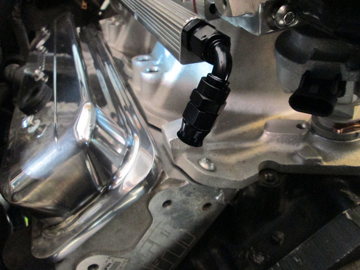
Fuel line fitting:
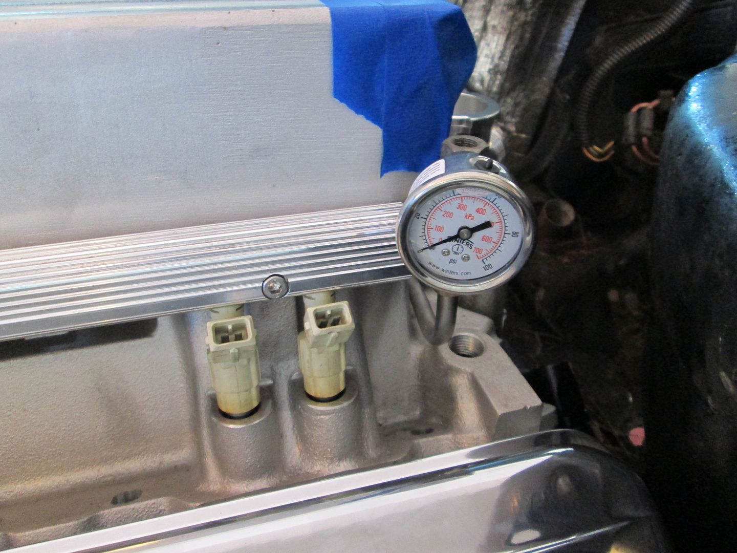
Fuel pressure gauge:
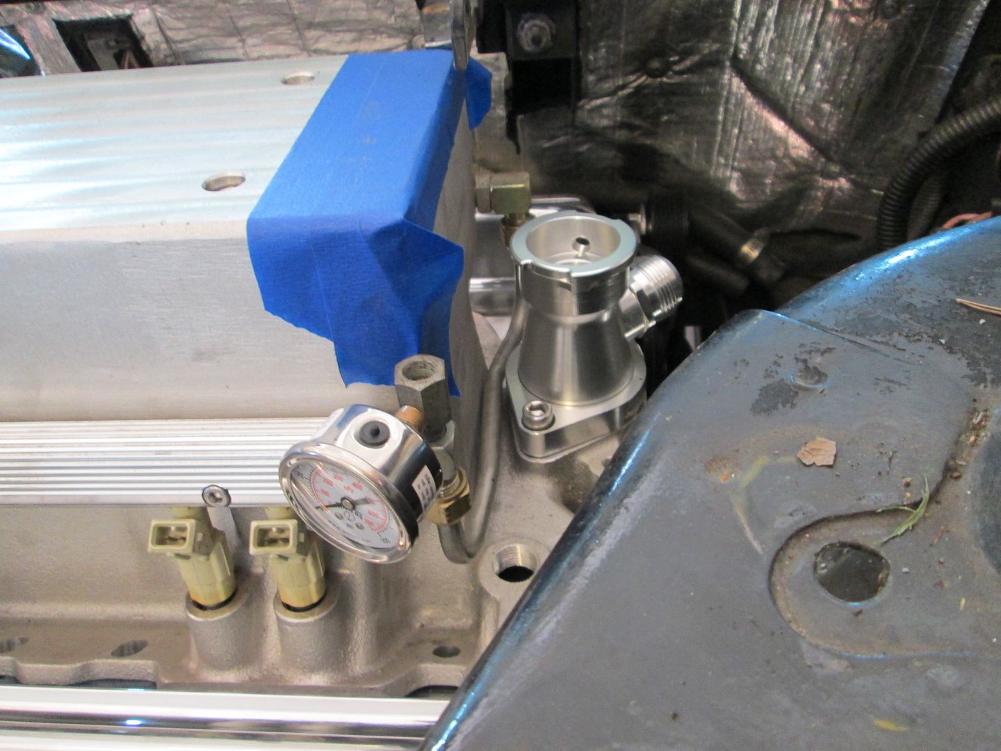
Themostat housing:
The heater hose will either come out here (after I drill/tap a hole):
Or here if I get a smaller fitting (to use the existing hole):
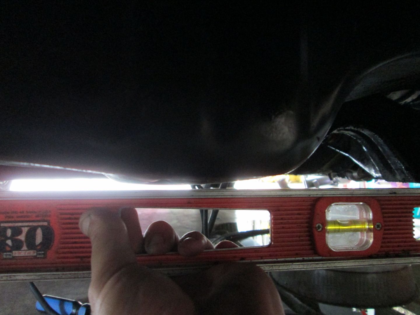
Mockup of the belt clearance... I will need to notch the current notch some (it doesn't go high enough to clear the angled belt:
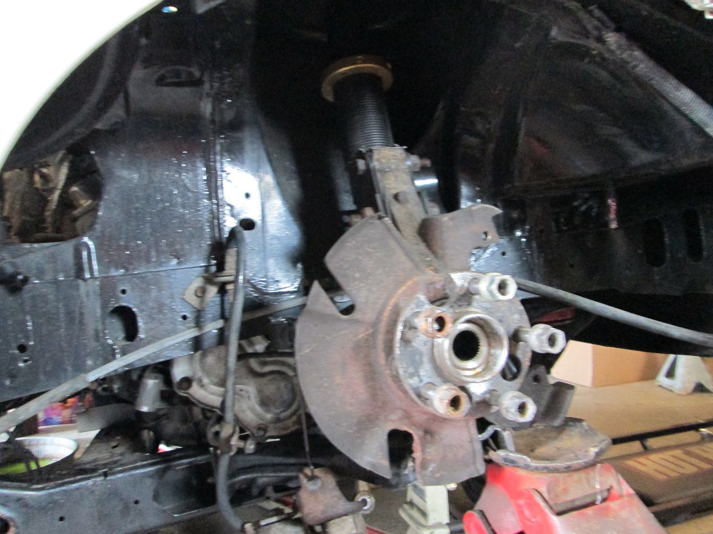
Finished the preliminary engine placement tests today. Removed the spring and put the upright/strut back into position and raised it till the strut bottomed out or it hit something. Good news is that on both sides while clearance is very tight, the strut bottoms out before the lower a-arms make contact with the transmission or the front engine mount. Fully compressed:
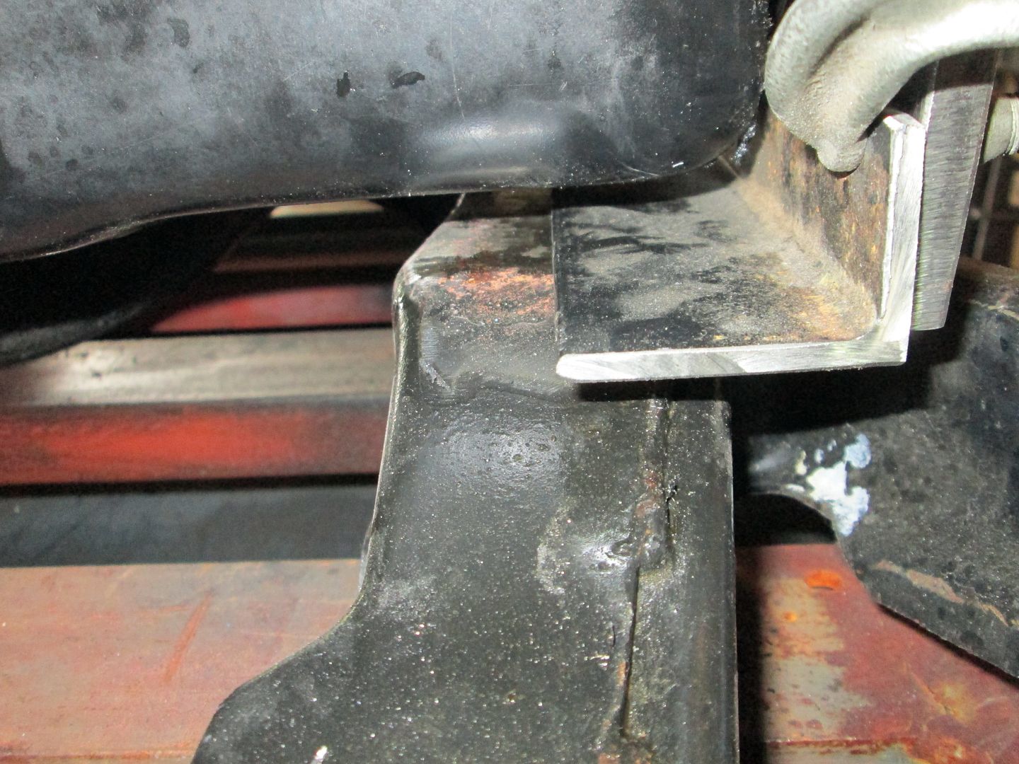
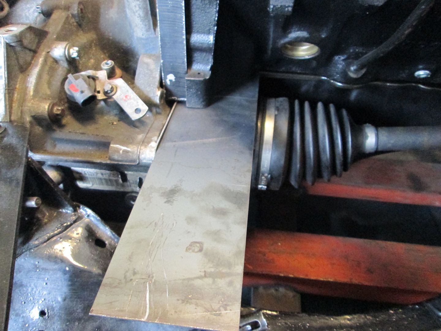
Very small gap between the transmission and the a-arm:
Pretty much the same gap on the passenger side as well (I was able to pass a piece of paper through the gap):
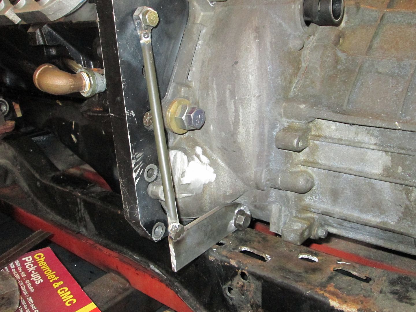
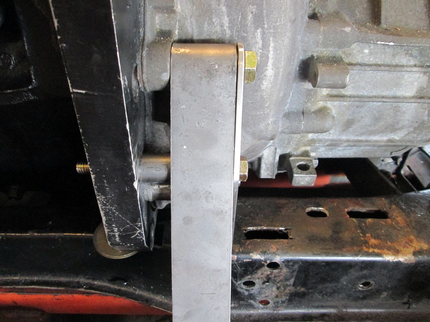
I scribed the location of the mounts on the cradle, so I could replicate the placement. Then it was time to remove the drivetrain and get it back on the fixture. Used the marks to position it and made sure it was square and level in both directions. Once that was done, I started working on the front transmission mount.
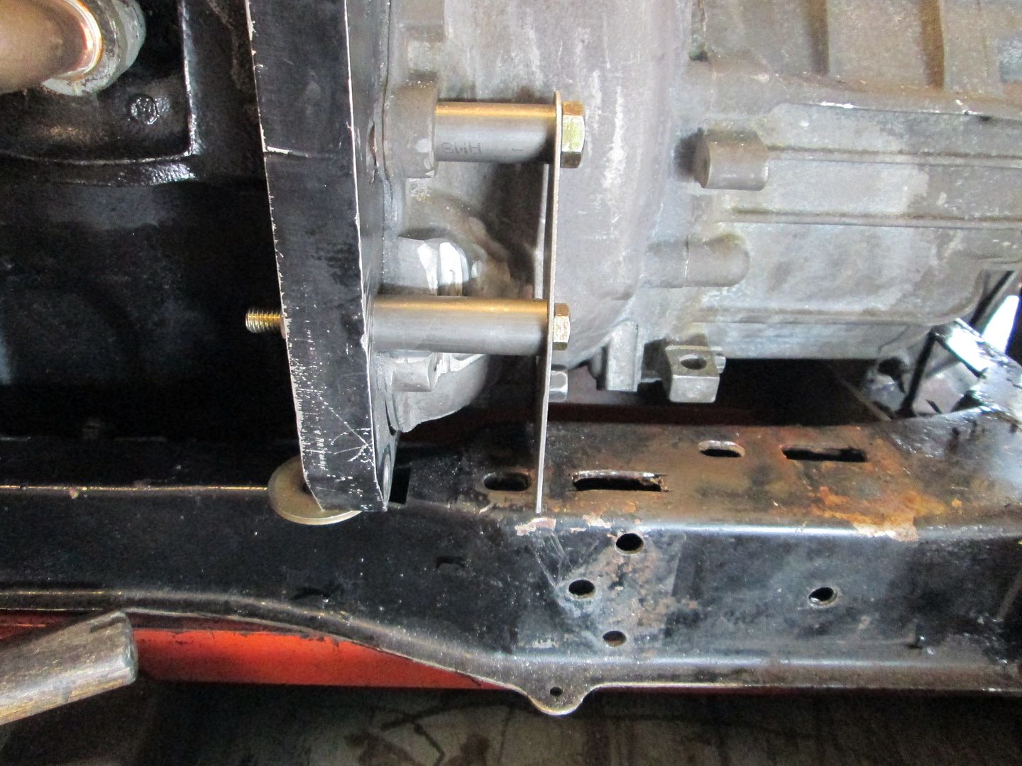
I like to use a minimum of 3 bolt holes for my mounts and decided to use these 3 holes. One is a transmission hole, one is the top starter hole on the Archie adapter plate and the last hole is a bellhousing bolt hole. None of the holes are in the same plane, so I made some spacers from 3/4" tube with 1/8" wall. This is a good fit for the upper bellhousing bolt (now 1/2"), but the started bolt is 3/8" so I turned down a sleeve for an aftermarket sway bar link for a bushing:
Before the starter bolt spacer could be installed, I had to clearance the transmission slightly with my die grinder. This area had been previously clearanced by someone else... I only did the smooth shiny part. This area will be covered by the mount so it will be hidden from view:
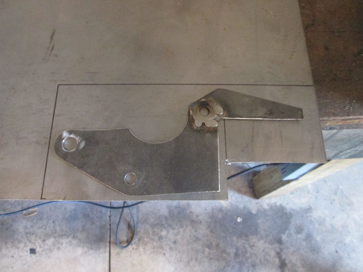
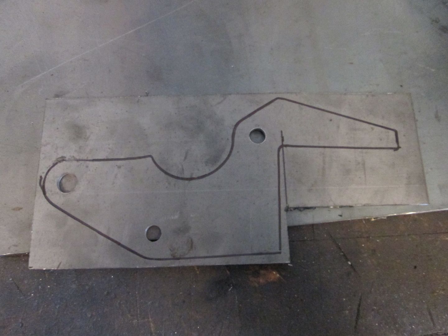
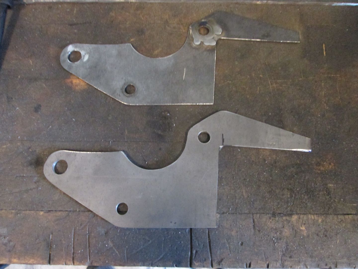
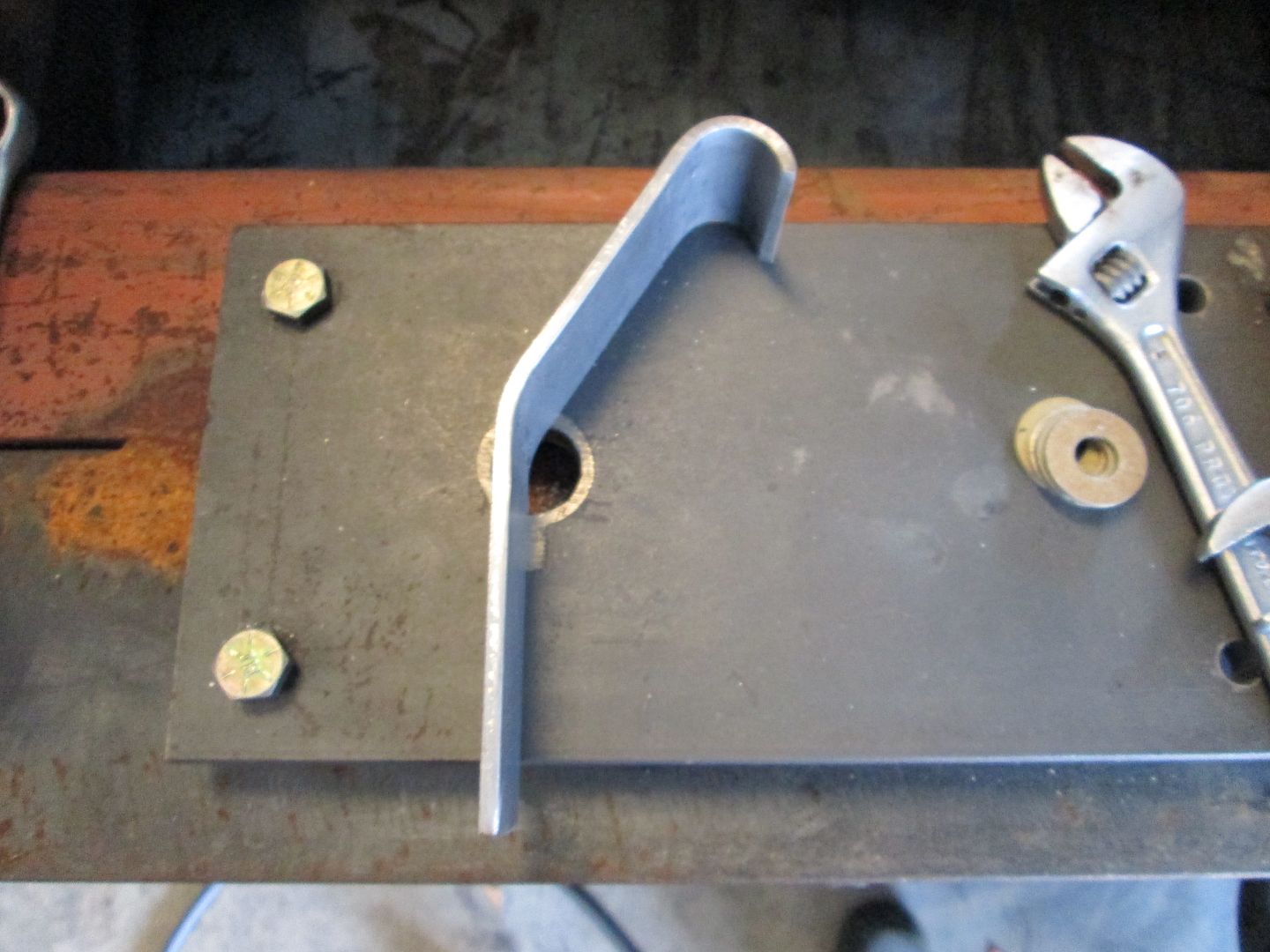
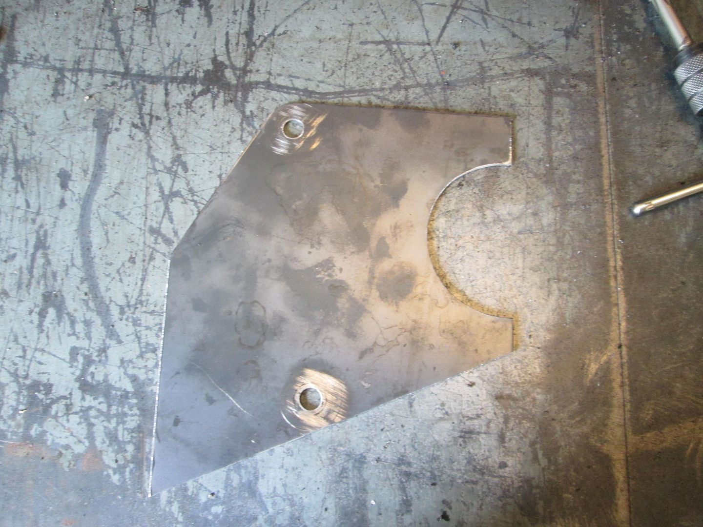
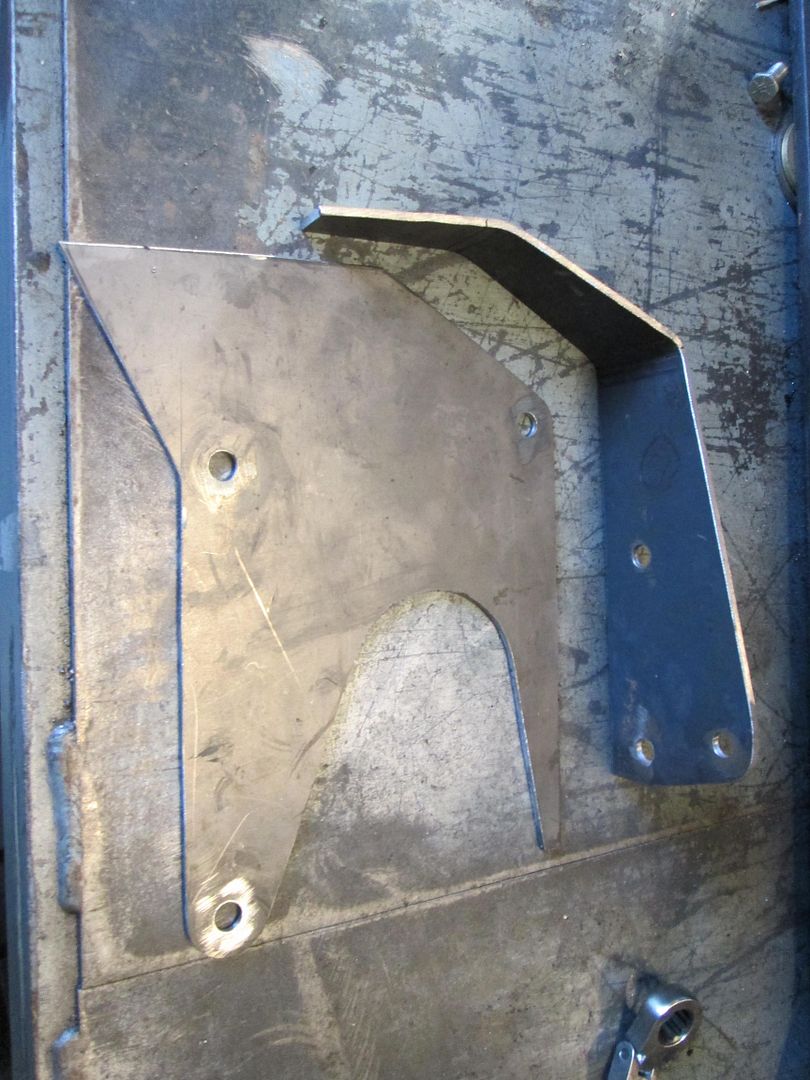
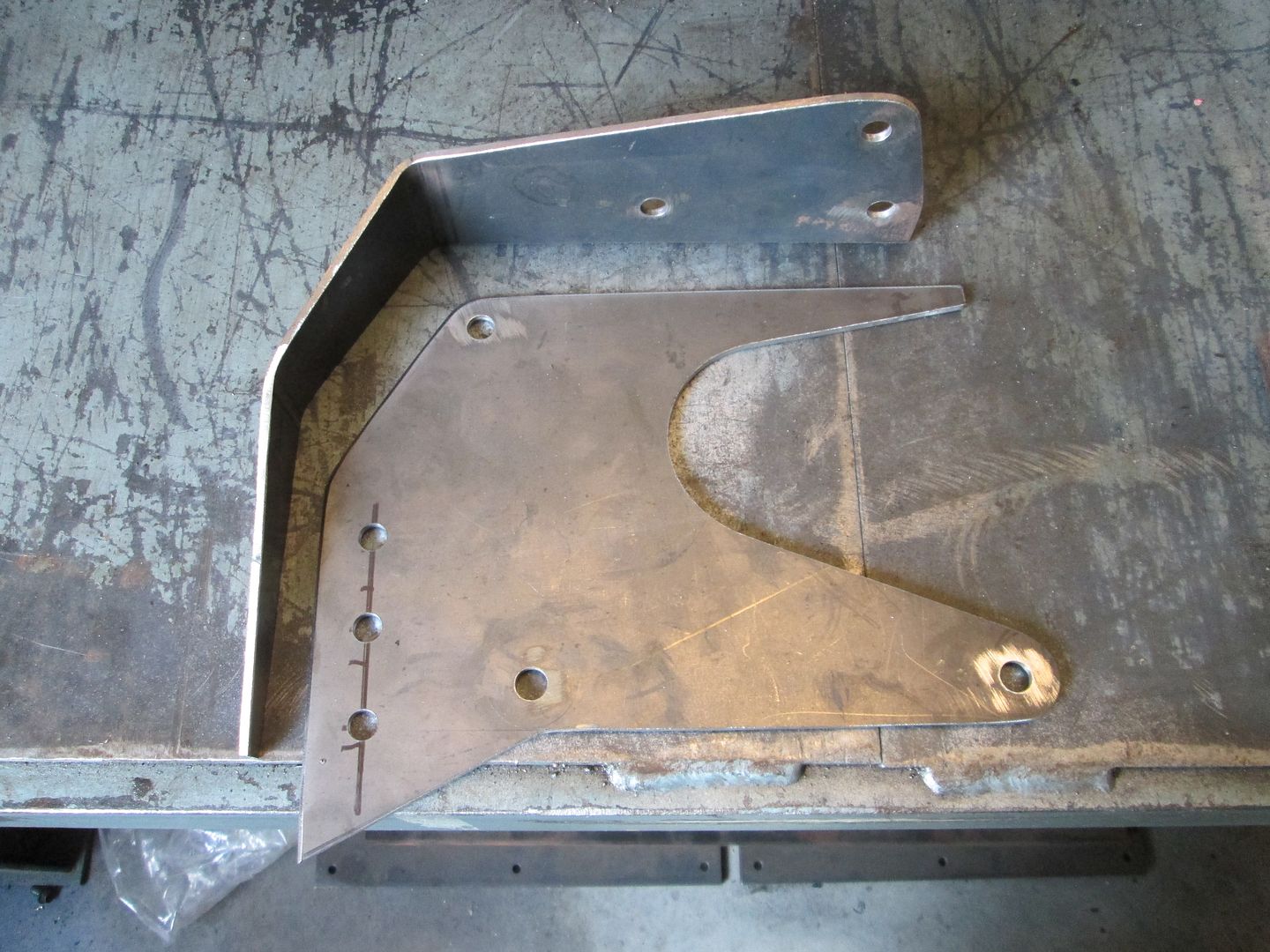
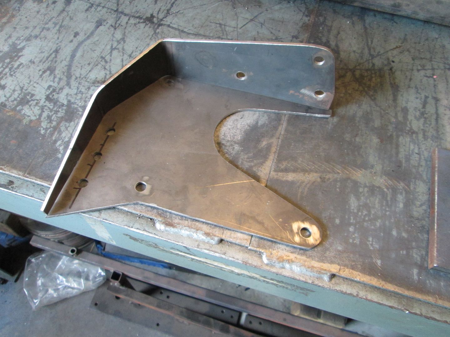
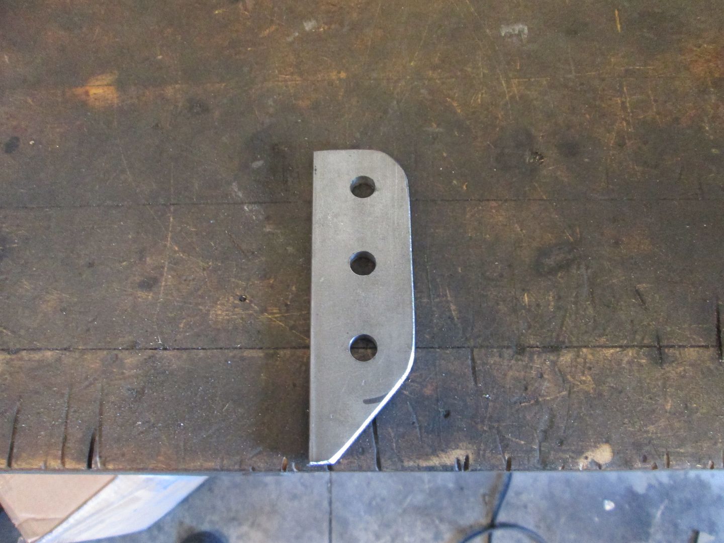
Here is the 16ga template I used for mockup and the spacers. This template will be transferred to 1/8" steel plate and cut to the same shape for the final mount:
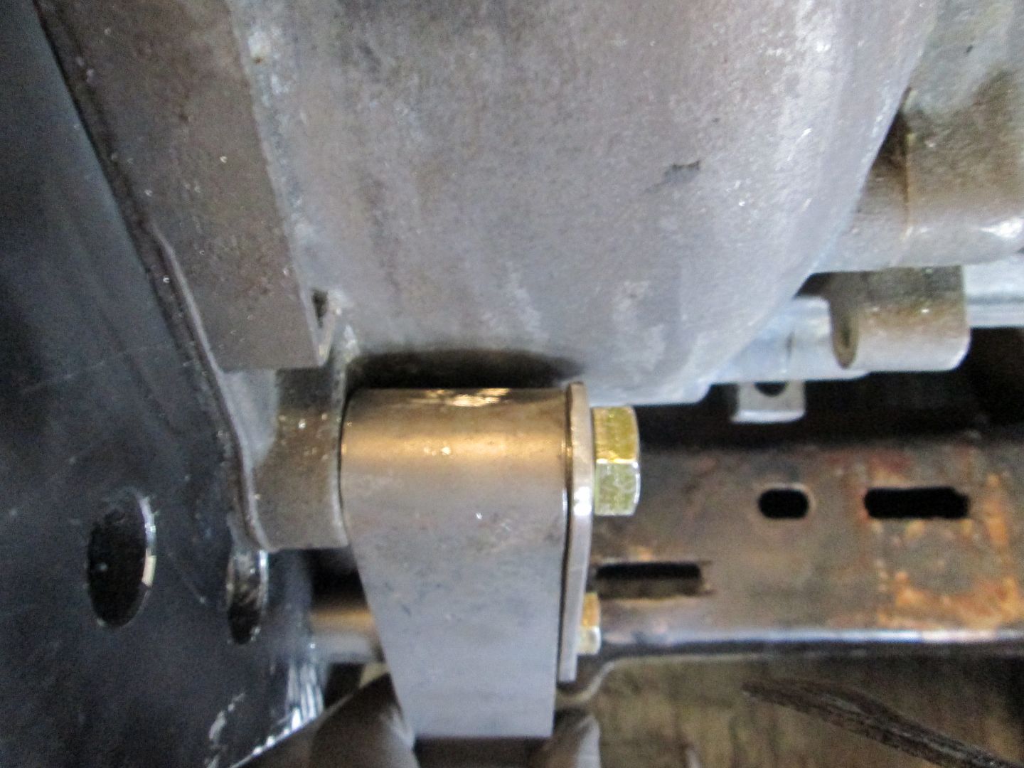
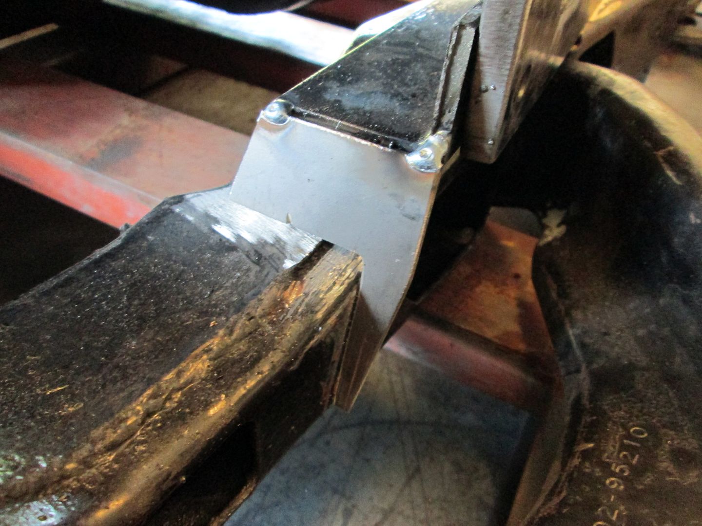
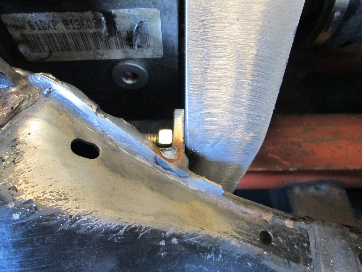
Notice the nice uniform gap between the bracket and the transmission case... I am anal like that:
There will be 1/8" plates that fill the gap between the spacers and down to the cradle. This will triangulate everything and result in a very strong/stiff mount made from 1/8" steel. The added steel plates will also completely hide the previous mods to the transmission case for the previous mounts:
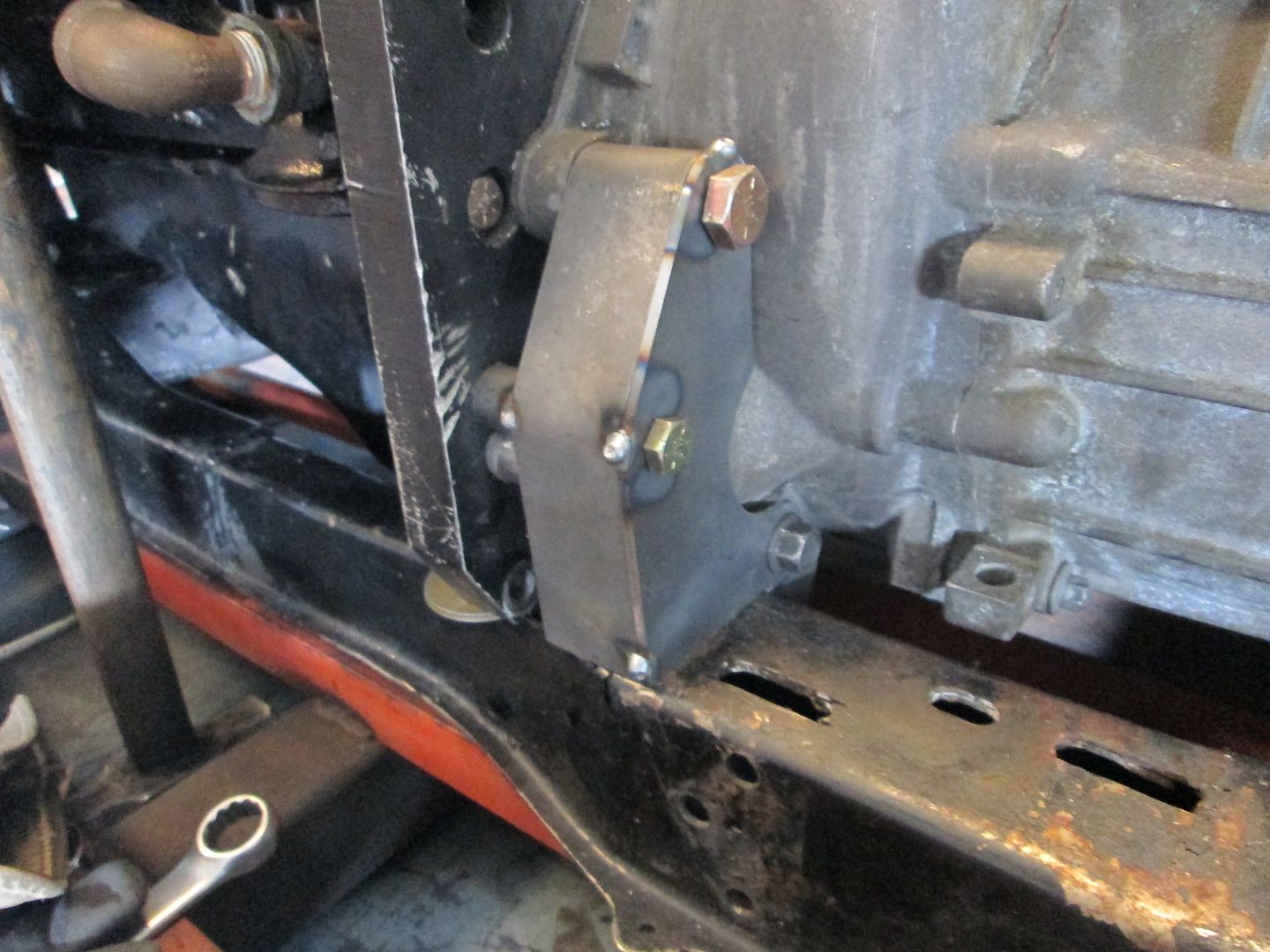
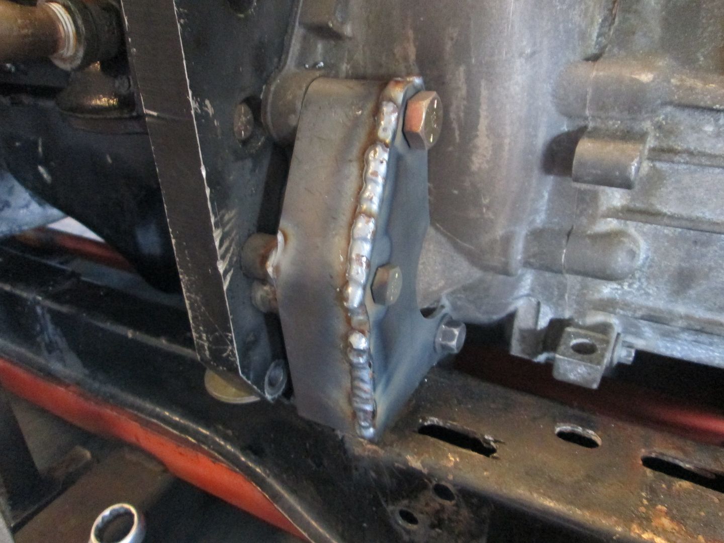
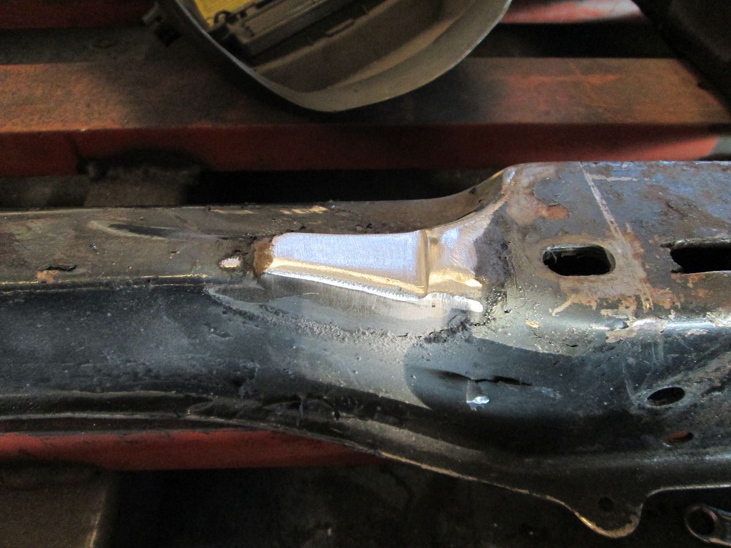
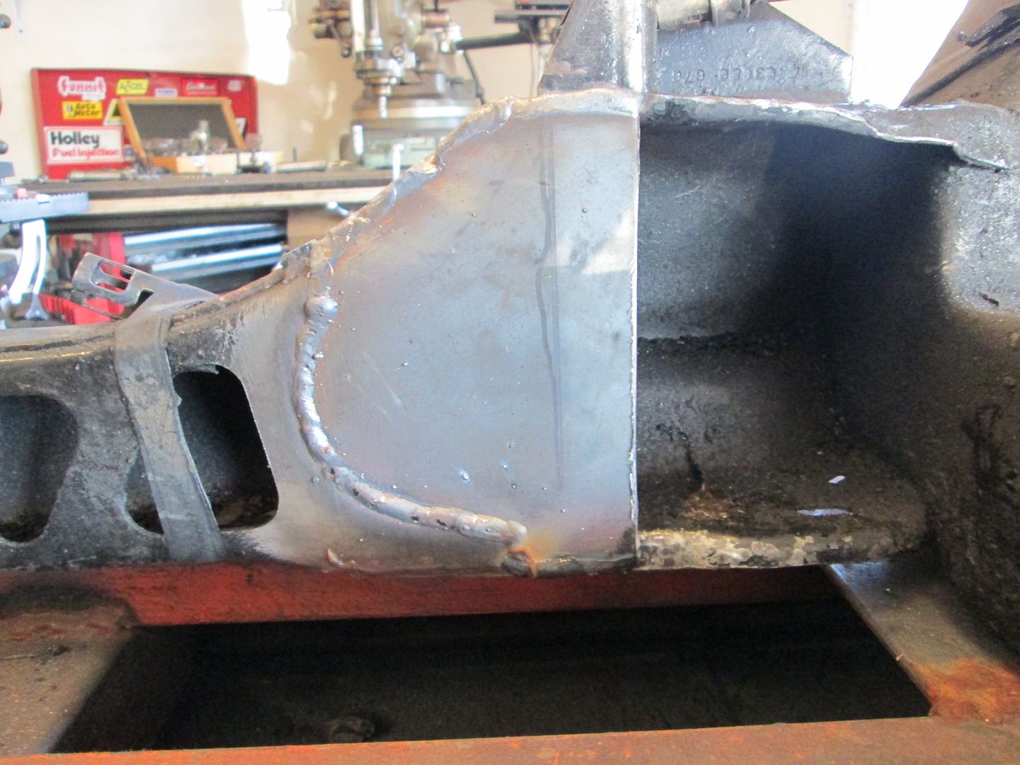
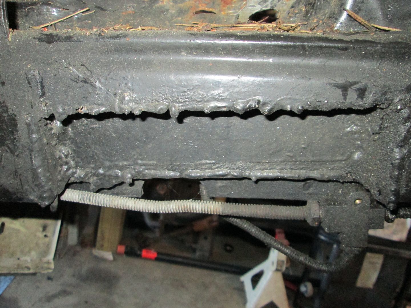
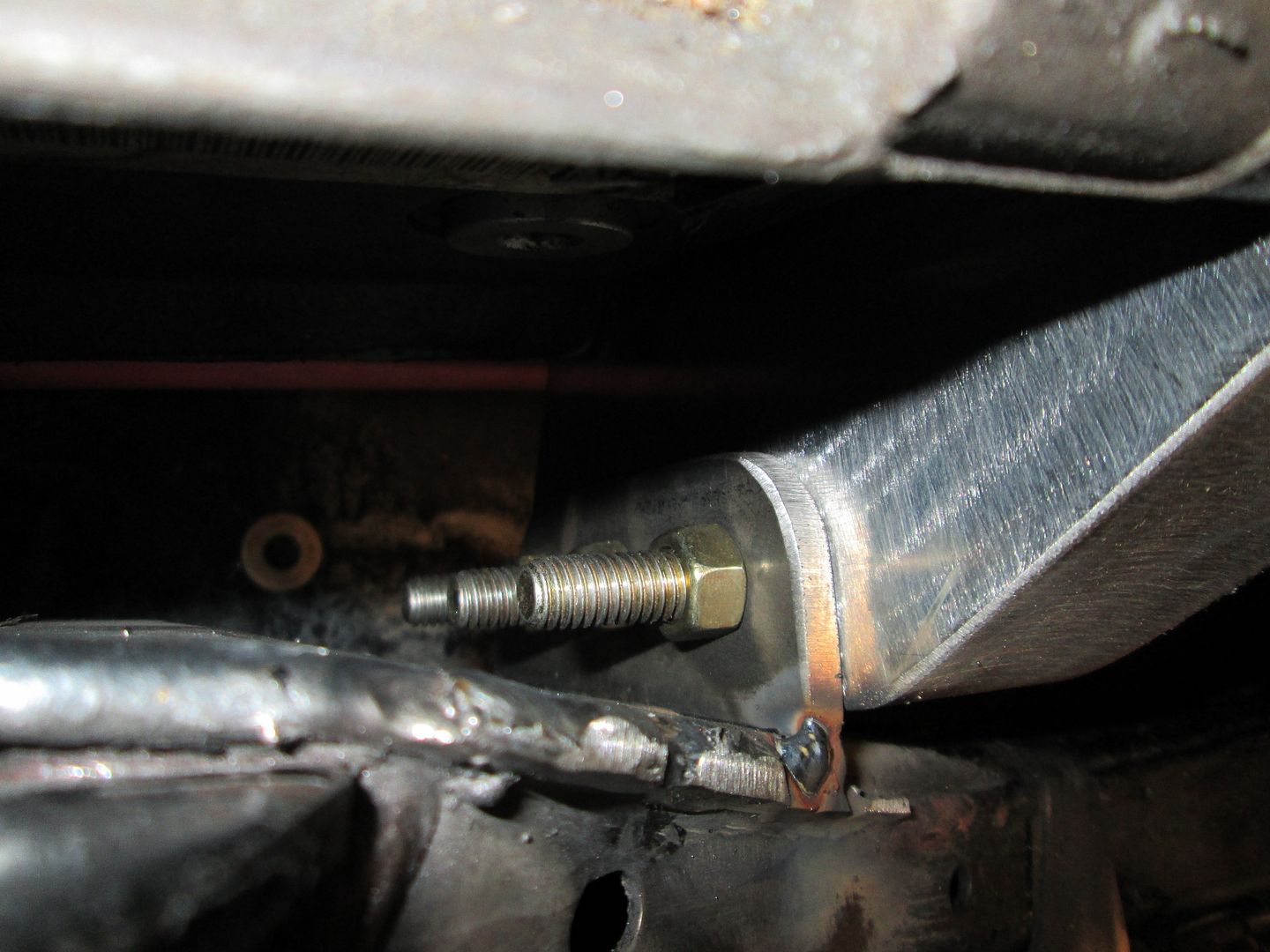
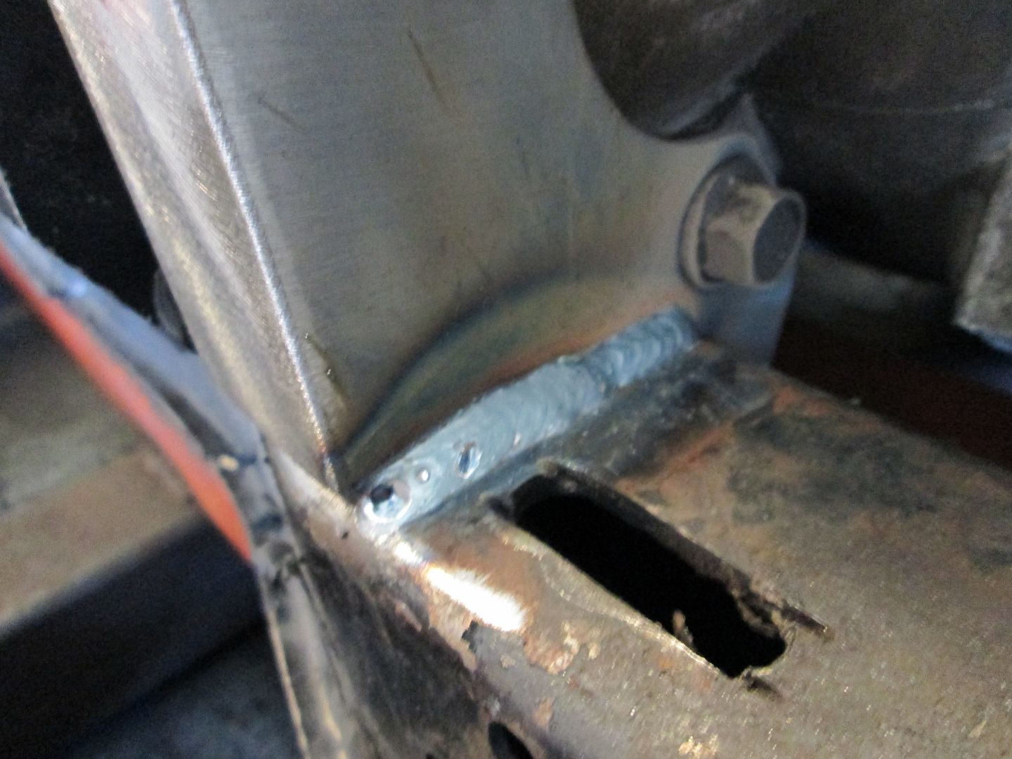
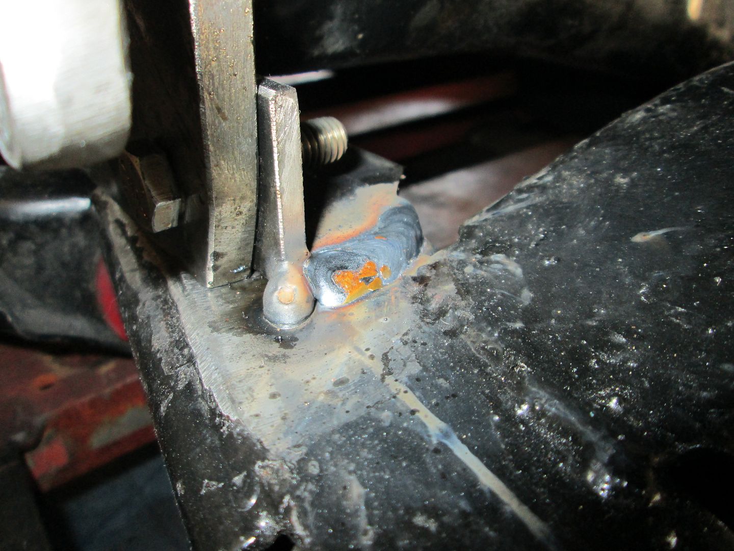
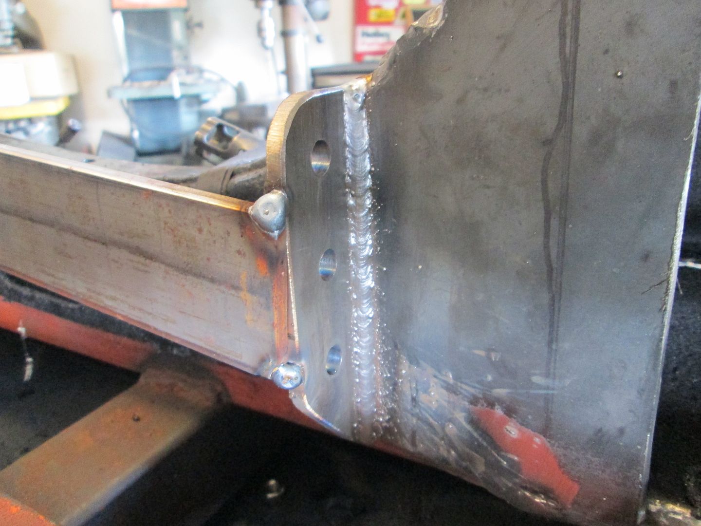
This mount will be welded directly to the front cradle rail to help spread out the load. The previous mount used 2 bolts and the cradle rail is bowed up where the drivetrain torque was too much for the metal around the 2 holes to properly hold. While this mount will be welded to the cradle, there will be a set of bolts for all mounts that secure the drivetrain in the same direction - remove the bolts and the drivetrain can be freely shifted to the passenger side for removal and lifting.
Sunday I hope to get this mount finished in 1/8" steel and start the mockup/template process for the rear one.
Though the discovery of my cradle showing stress from the torque makes me extremely glad about the timing of this project. Nightmares of what could have happened if that broke loose...
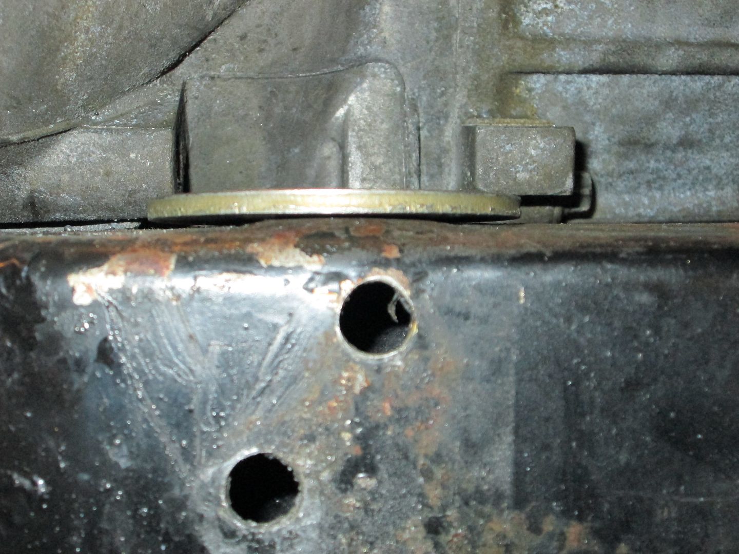
Here is a visual of the bent portion. The washer should be flat, but the center is bulged up where it was trying to pull through the enlarged bolt slot.
Your engine had 381 rwtq, so at the flywheel its pushing about 426 ft-lb (assuming a 12% driveline loss). With the F23 in first gear the axle torque (shared between the two axles) is 6008 ft-lbs... That is A LOT of torque for your mounts to withstand in the event you can hold traction in 1st gear.
For comparison, my LS4/F40 is 325 rwtq, so it is about 364 ft-lb at the flywheel and 4871 ft-lbs at the axles.
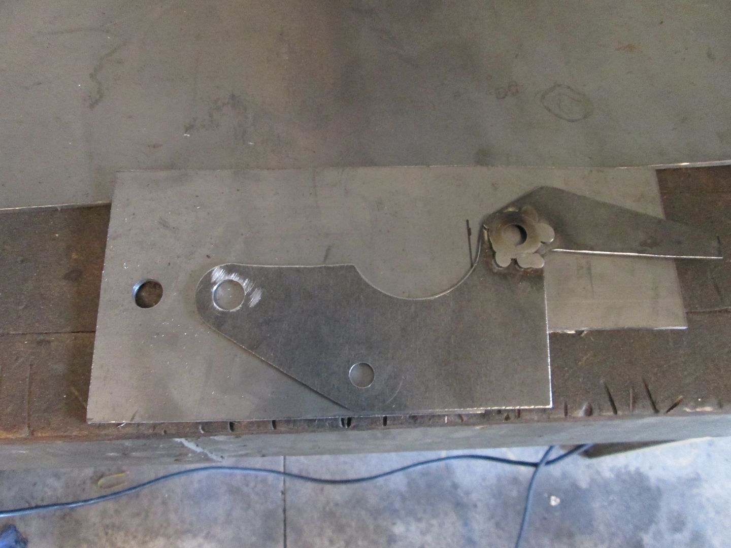
The front tranmission mount is nearly complete (just need to smooth the welds on the outside and finish welding it on the inside) and I thought it would be helpful to show a little bit more of the mount making process.
Starting with the template, I grab some 1/8" sheet and cut out a section of if for the piece I need:
With the template sitting on the steel, I mark the first hole and drill it to the size of the bolt (keep the holes as tight as possible).
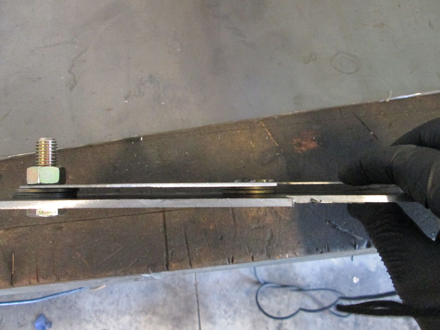
Once the hole it drilled, now tightly bolt the template to the steel plate and use 2 washers to keep the two separated. The separation allows the drill bit to center on the template as it drills the 1/8" plate. Drill another hole.
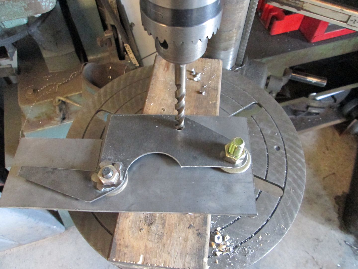
Then add a bolt to the new hole with the needed spacers and drill the next hole. By doing it way you keep the template secure and have a precise transfer of the bolt hole pattern from the template to the steel.
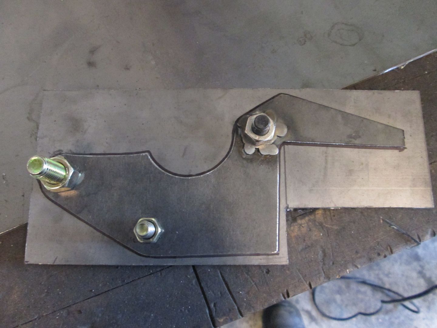
Now remove the spacers and bolt the two back together, then take a sharpie and mark the needed shape.
As you cut the shape out, cut in the middle of the sharpie mark and try to leave a little of the mark for finishing.
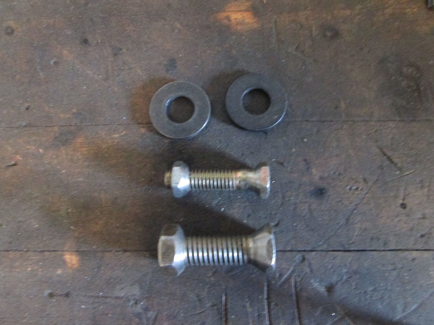
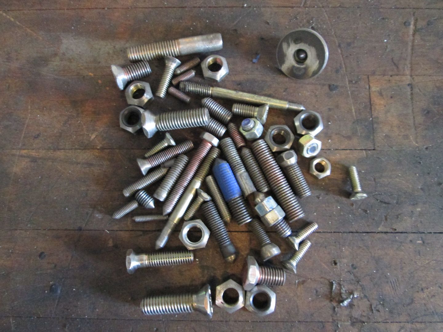
Once the rough cutout is done, bolt the two pieces together again, but now add washers to the holes that have smooth radii. If the washers with the right OD have too large of an ID to center on the hole, chuck up the bolt in the drill press and use the hand held grinder to taper the head or nut so they will self center to larger holes. Here are a bunch of modified bolts I have used over the years. The ones with the point are for transferring hole centers for making the templates, the tapered nuts and heads are for centering washers for shaping in larger holes.
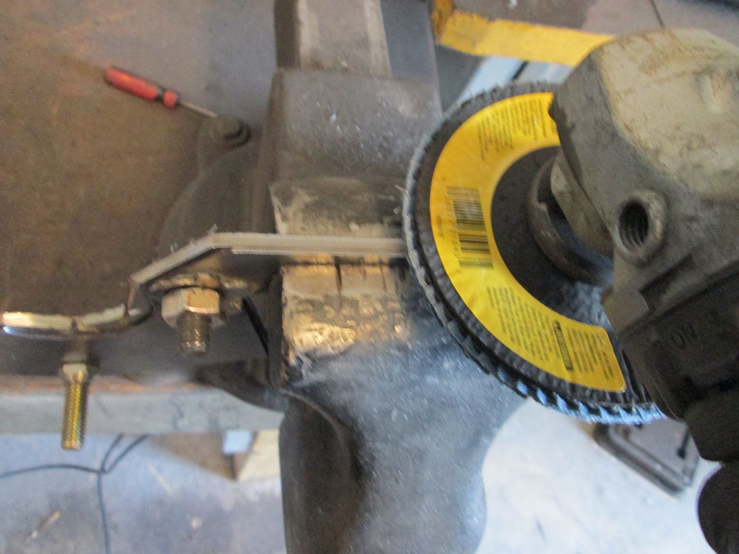
Then use a grinder with a flapper disk (36 grit) and slowly shape the plate to the shape of the template. Go slow you just want to scratch the template surface and the washers are you round the edges. With some work you will now have a copy of the template.
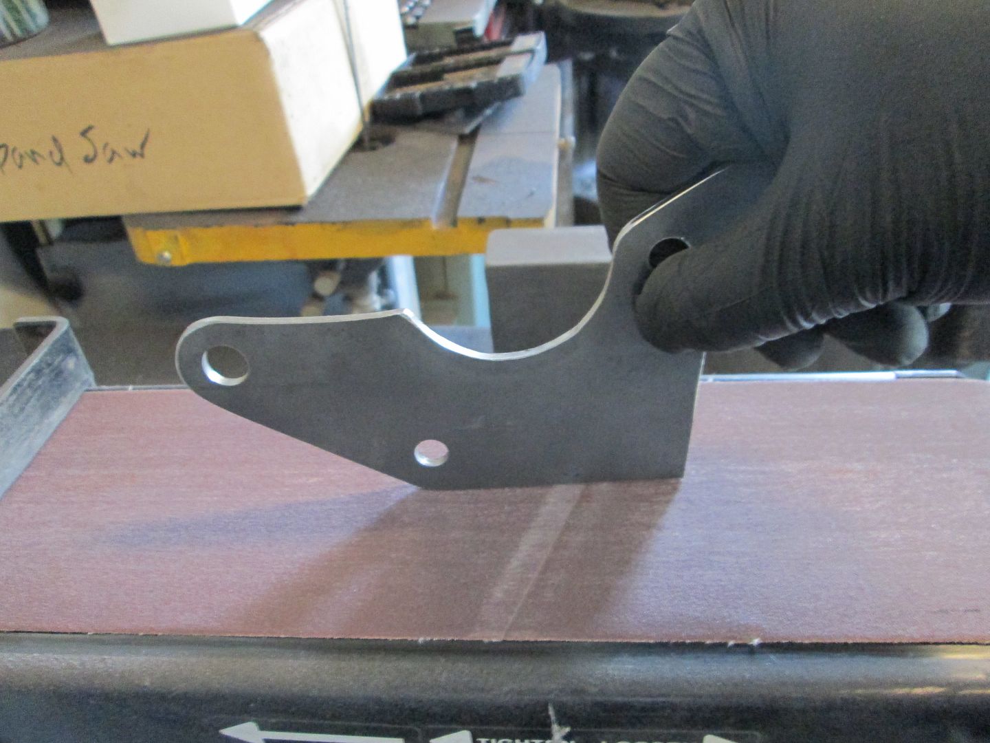
Next I use a belt sander to help flatten any straight surface (but a flat file works as well) and smooth out the edges.
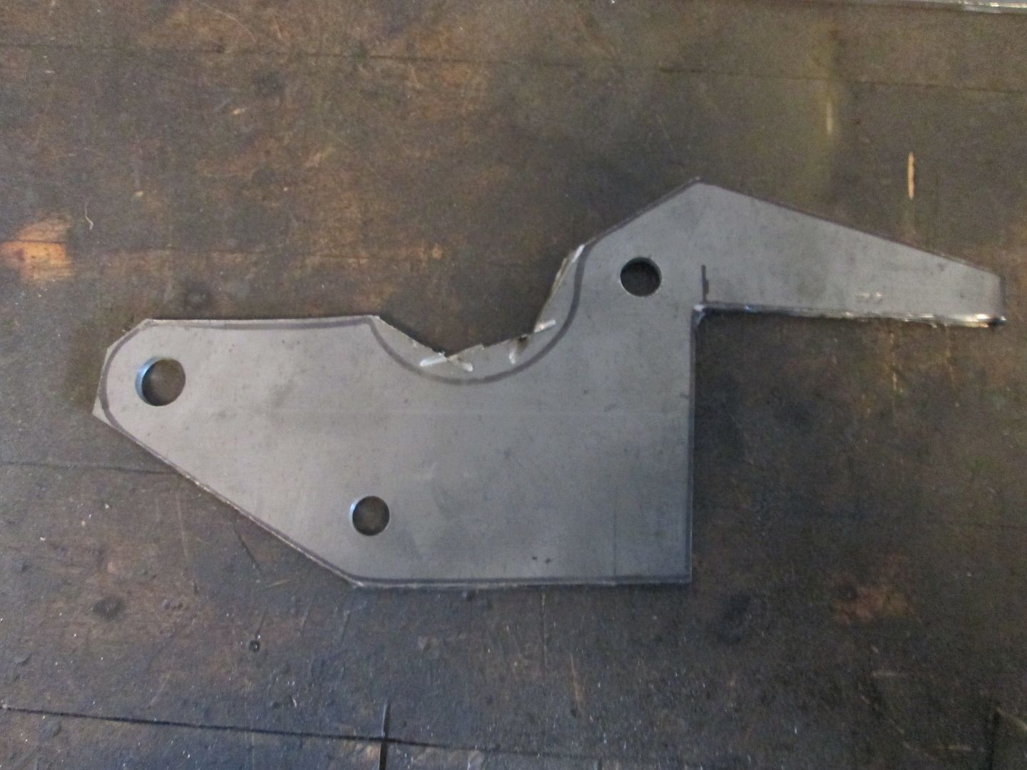
Here the 1/8" steel bracket is now done.
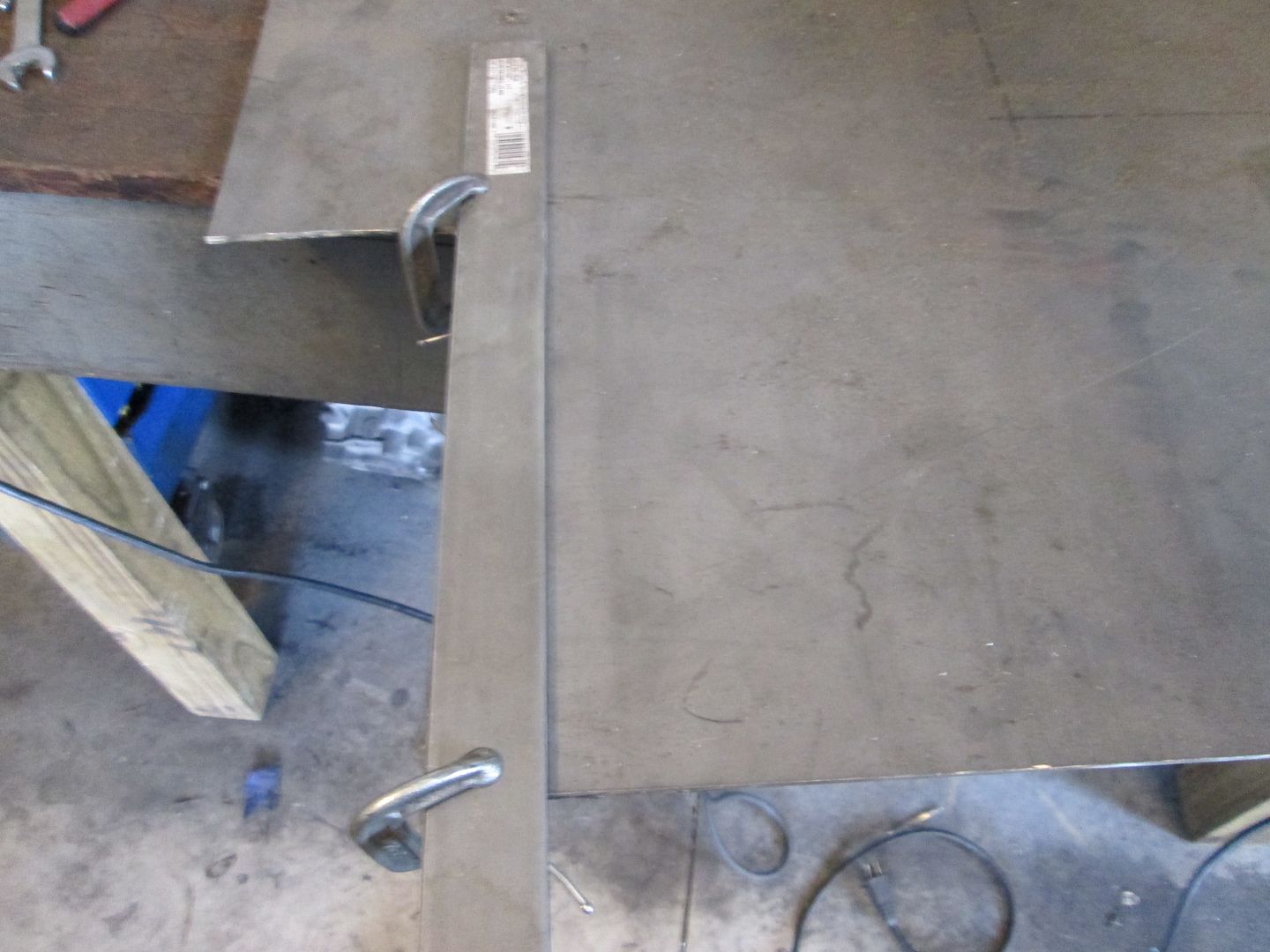
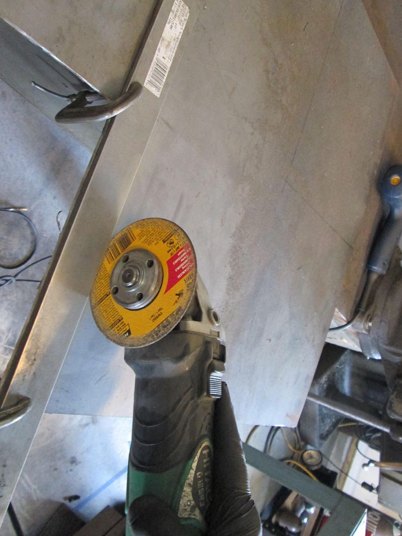
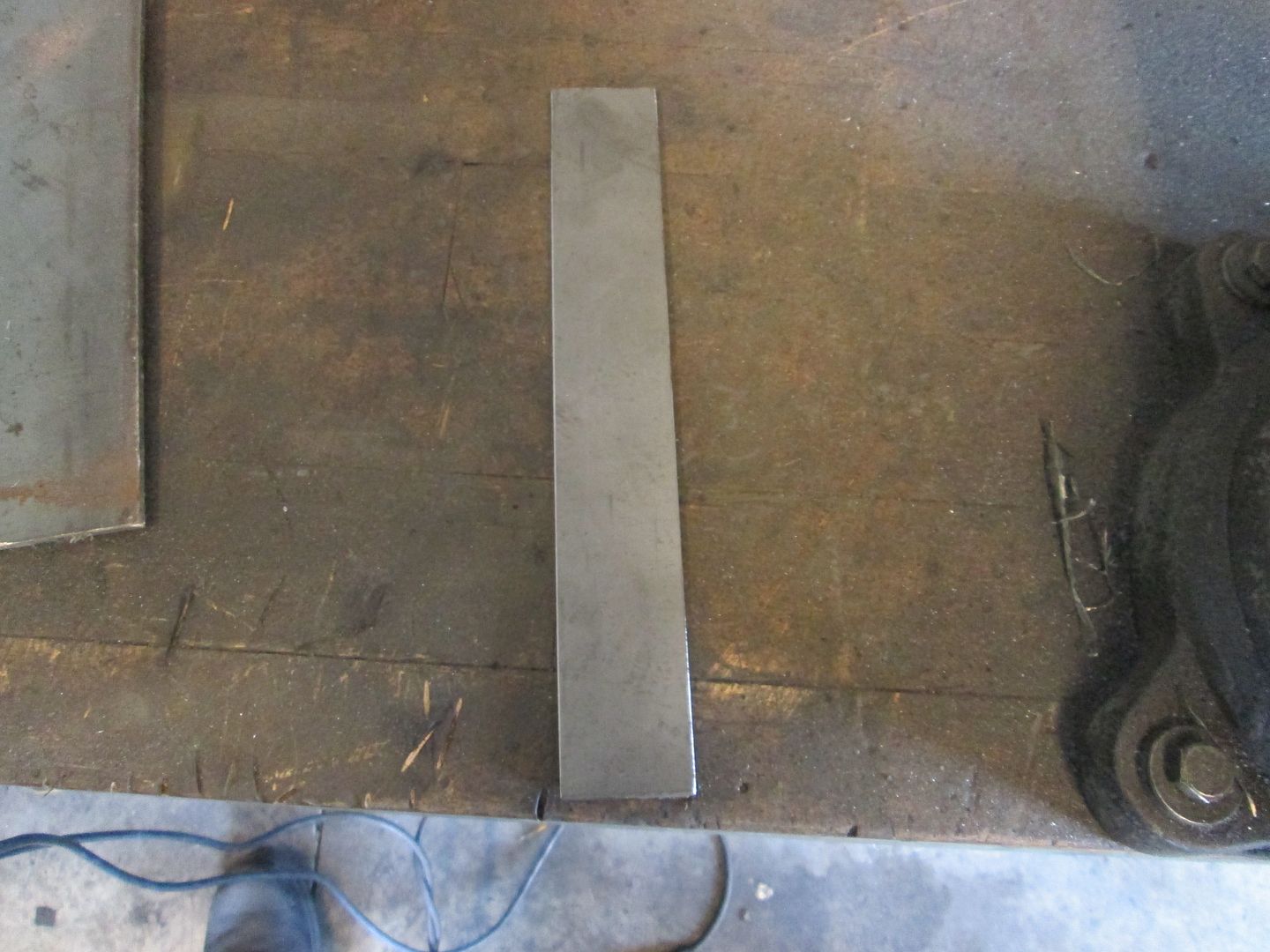
I wanted to add some 1/8" plate to the firewall side of the bracket to stiffen it up and hide the previous grinder work on the transmission, so I cut a long strip of 1/8" material 1 1/2" wide. When I want to make long cuts that are straight, I use another piece of steel as a guide and clamp it to the metal to be cut.
Now here is where I get a little fancy... I want this 1/8" plate to curve around the top spacer sleeve. To do this I grab another piece of stock used to make the spacer, clamp it on the vice and start pulling it over the tube. Several hits with the hand held mini sledge works to persuade it to bend tighter.
To go even tighter still, I clamp it in the vice using a socket to hold the tube tightly in the groove. Then use a large c-clamp to pull the short leg further around the tube. Once I am happy with it, I cut off the excess length of the leg and test fit the piece.
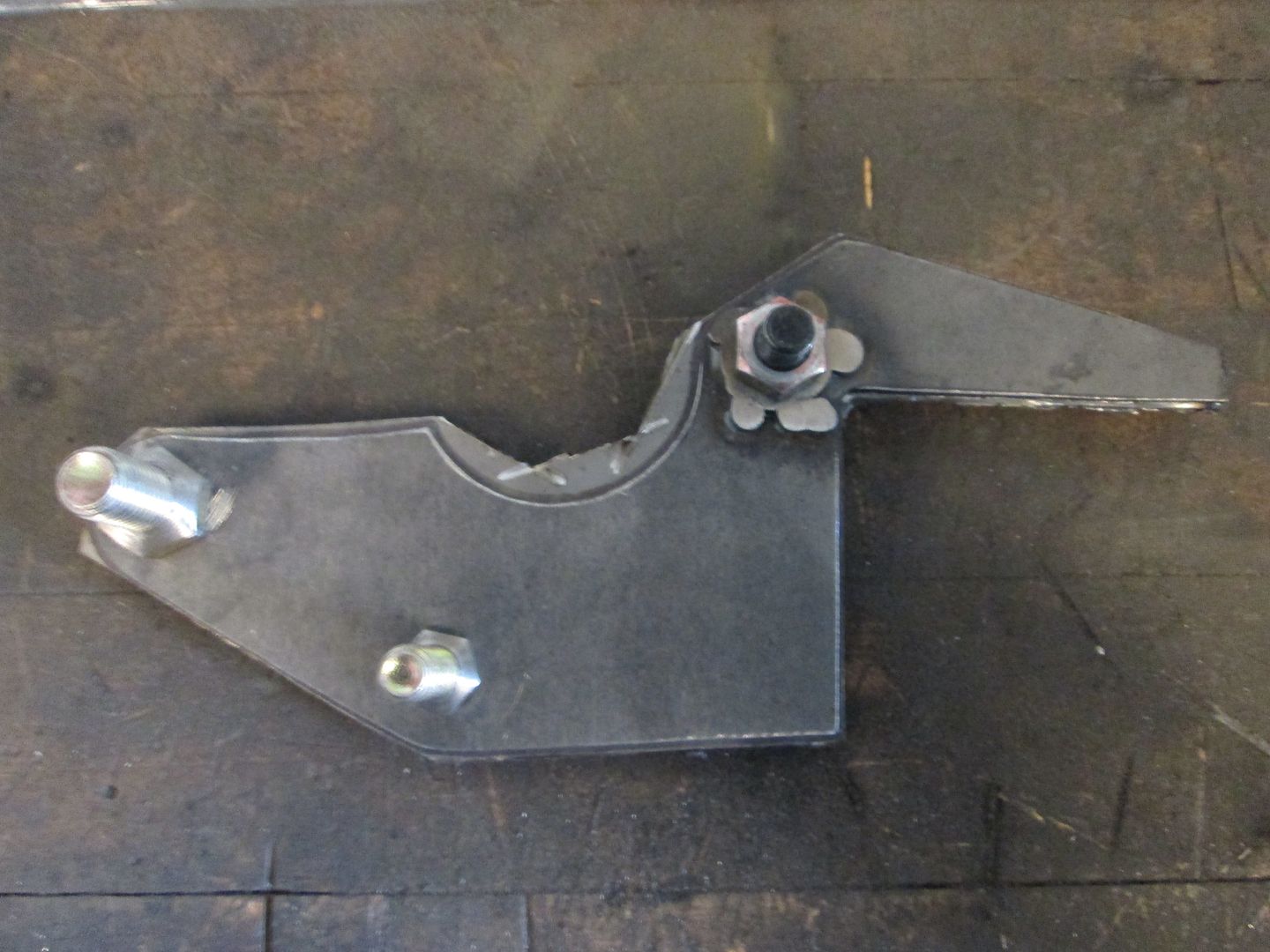
Then I slide the 1 1/2" plate into place and test the fit:
Then use the same process to make the 2nd bend around the other spacer and trim the bottom to the needed length:
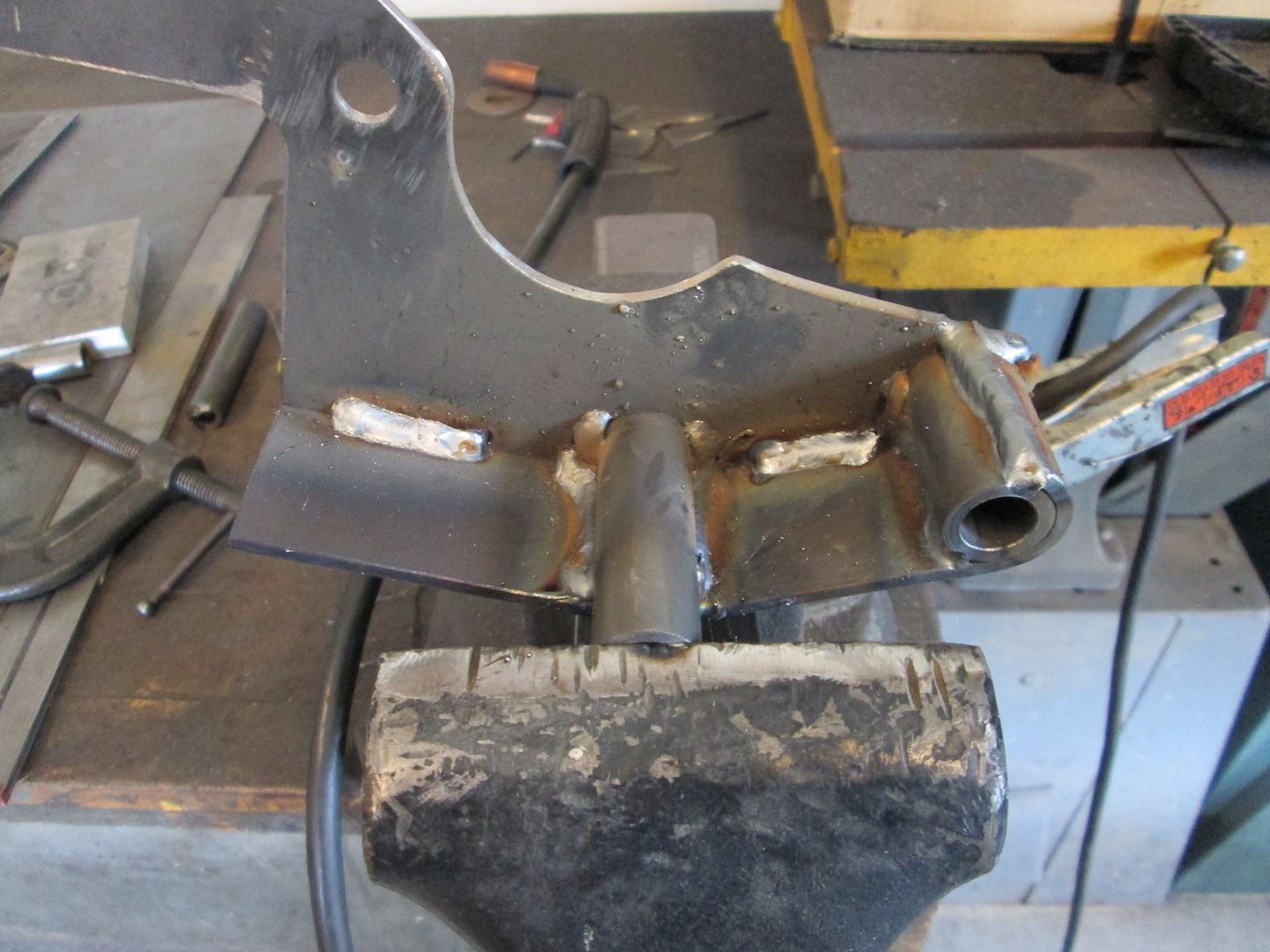
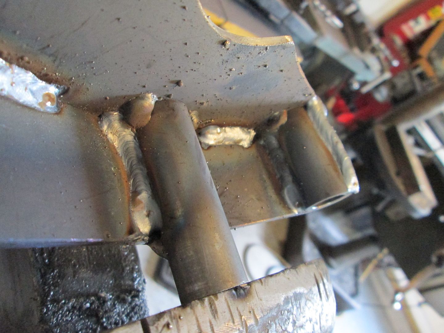
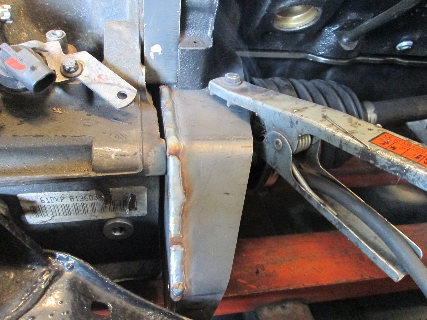
Then I tacked the spacers to the original bracket plate on the inside, then tacked the outer plate as well. Then went back and fully welded the two together. I didn't focus on making a nice looking weld, just a hot deep weld with good penetration as it will all be ground down anyway.
Backside is welded:
Last step is to grind the outer weld smooth, but the wife has a headache and would like for me to hold off on the grinding for a while. So I am going to mow the grass for a few hours.
[This message has been edited by fieroguru (edited 08-18-2013).]
And you did all that today, and got the post put together, and it's still early in the afternoon. ... you can really make a guy feel lazy sometimes!
With your bending setup, using the socket as a spacer on the pipe, is the pipe flattened out there? I would be worried about the pipe working/rolling free on the flat face of the socket when the wedging/bending force is being applied - or I could be missing something obvious that didn't translate in the picture/description.
Thanks! My parents owned an ornamental iron business in the mid 70's and it must have made some impression on me at a very young age. I vaguely remember being there while they were working when I was young, and they shut it down when I was 3-4. Kinda strange that my adult hobby ended up being my parents first business... now that I think of it, my mom has only seen the bed I made for Sara and I, she has never seen any of the brackets/mounts I have made for my swaps...
quote
Originally posted by Trinten: And you did all that today, and got the post put together, and it's still early in the afternoon. ... you can really make a guy feel lazy sometimes!
So I guess I shouldn't tell you that I didn't even step foot in the garage till 10 AM...
quote
Originally posted by Trinten: With your bending setup, using the socket as a spacer on the pipe, is the pipe flattened out there? I would be worried about the pipe working/rolling free on the flat face of the socket when the wedging/bending force is being applied - or I could be missing something obvious that didn't translate in the picture/description.
There is just enough pressure on the socket to hold everything in the vice, and the tube is 1/8" wall and quite stiff. The clamping/bending is happening with the large C-clamp, not with the vice at this point.
[This message has been edited by fieroguru (edited 08-18-2013).]
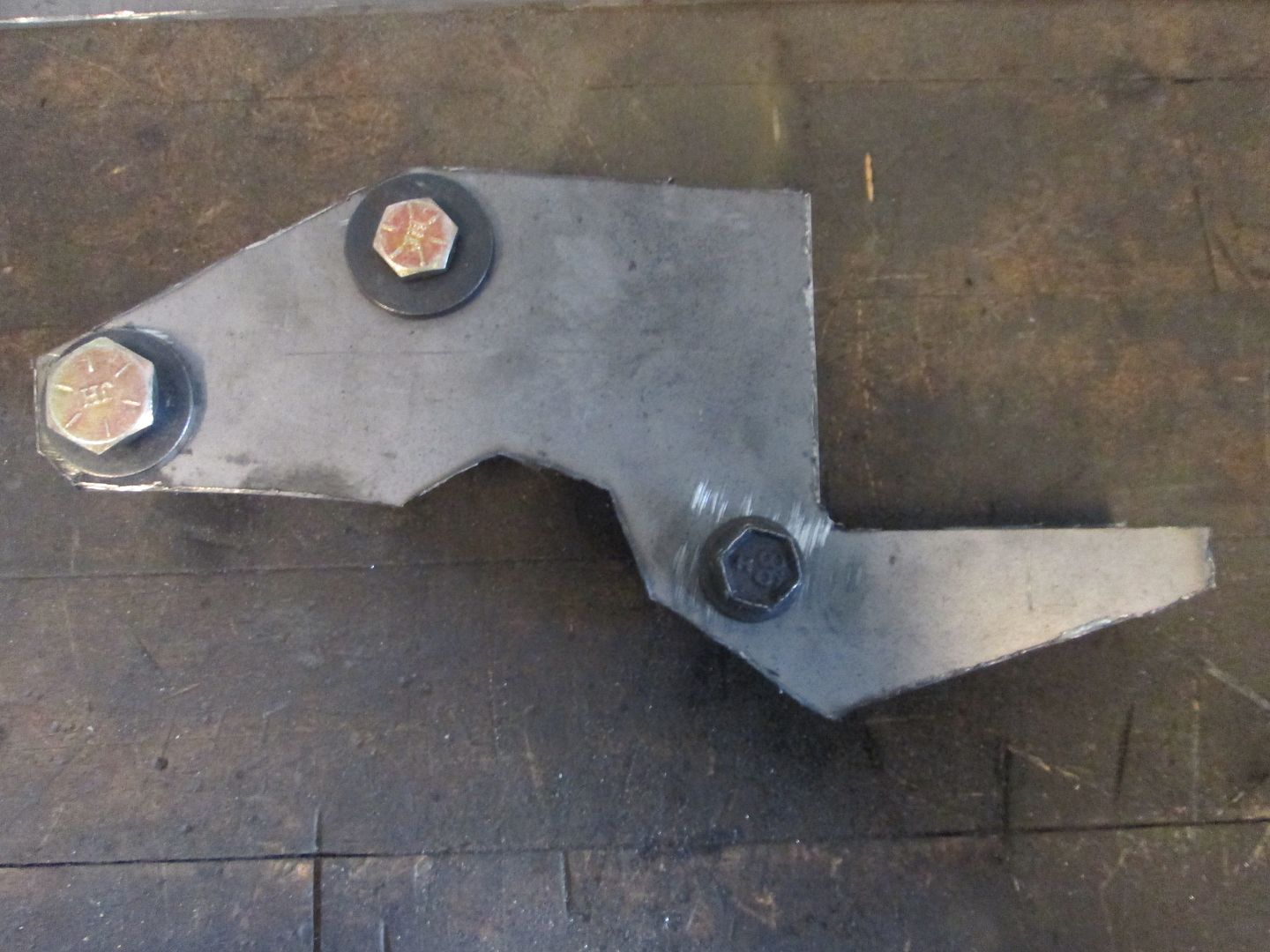
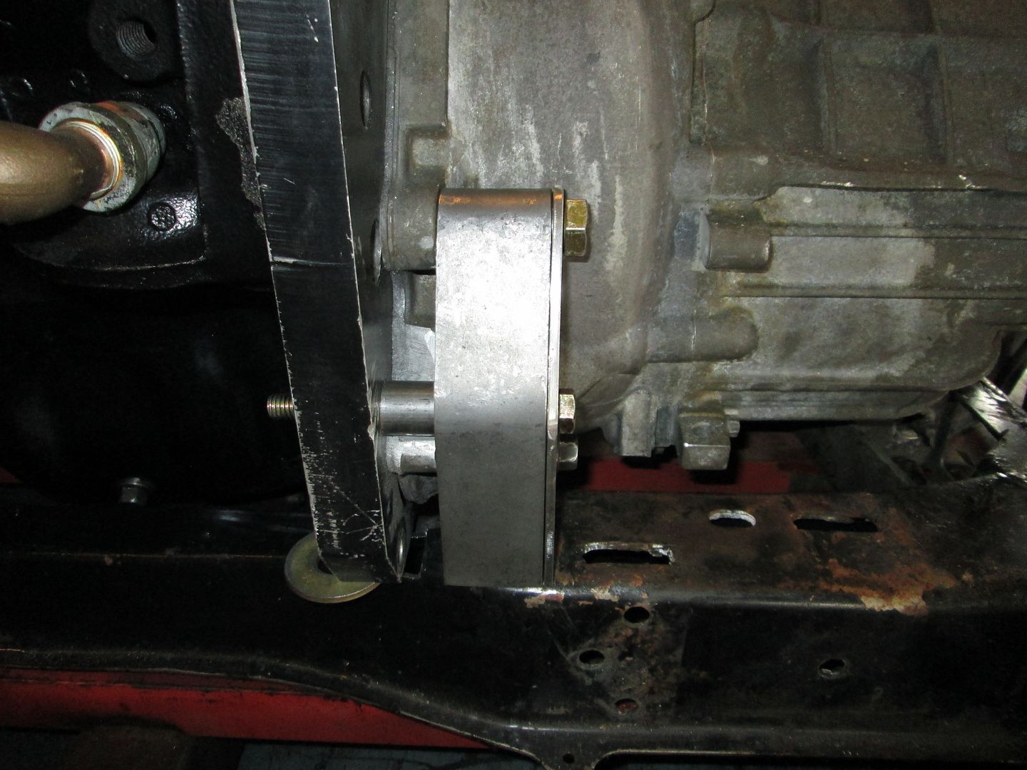
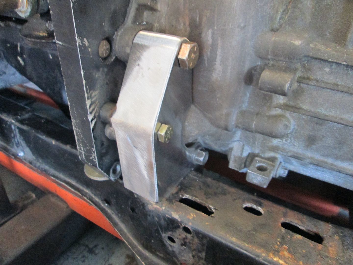
Here is the finished and smoothed front transmission mount:
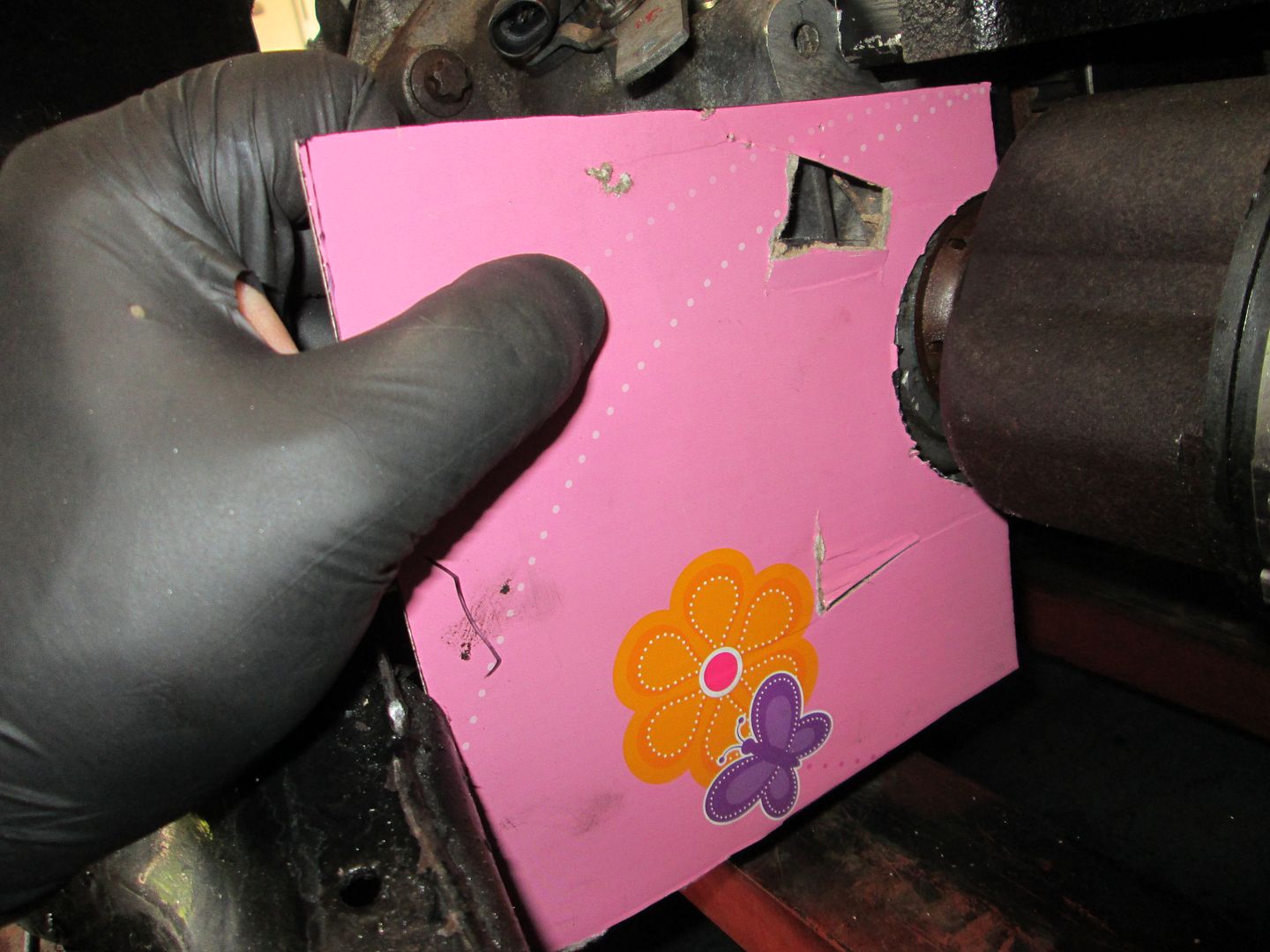
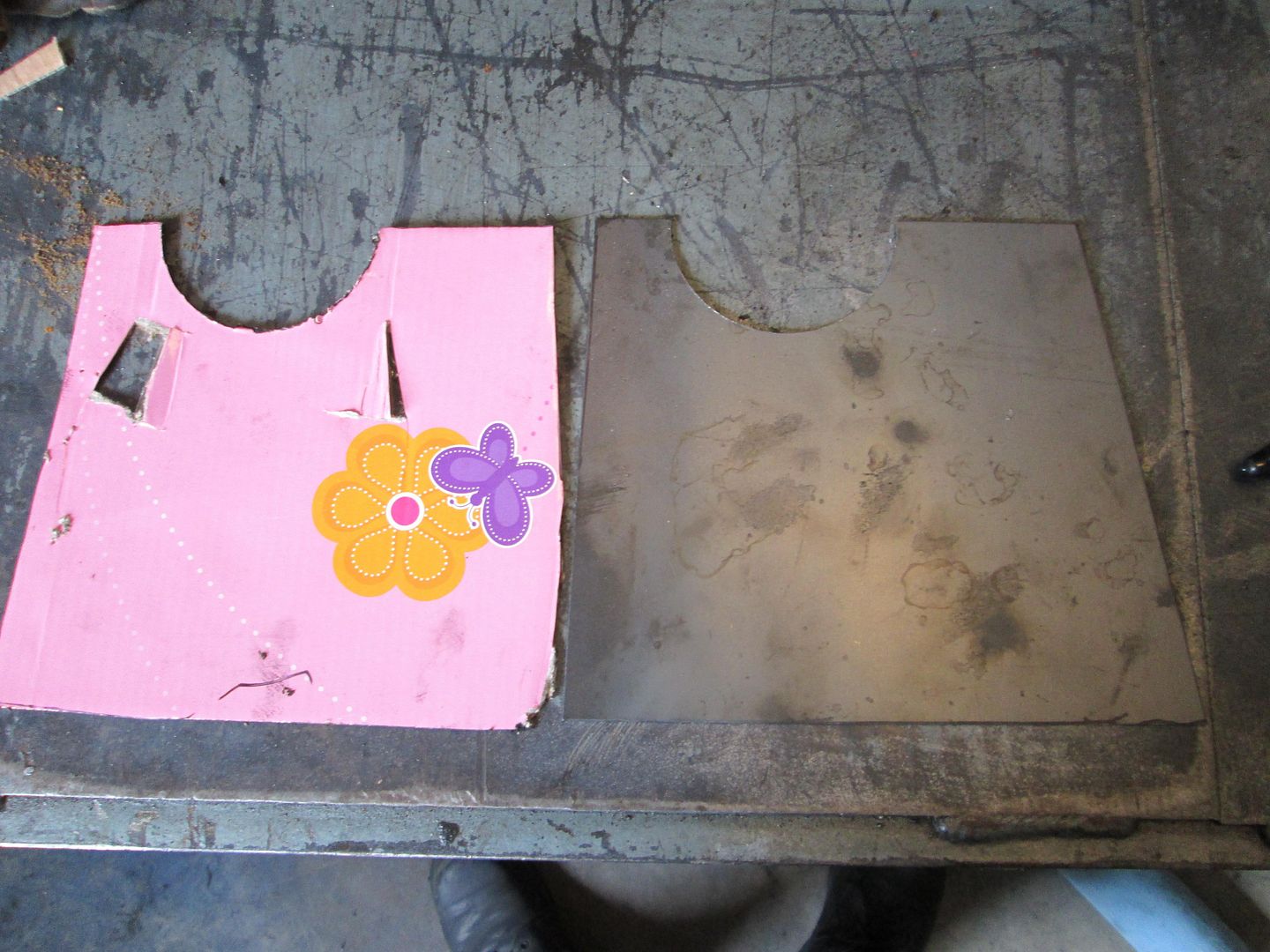
Then I started on the rear mount. Picked up some cardboard from the recycle bin (pink works) and roughed out the needed shape:
Transferred it to 16ga mild steel and made it a little larger. I used a 3" hole saw for the circular cut, but I need to see if I can find a 2 7/8" one for the final product:
Then did a test fit to make sure it would still fit in the area. I used the shear to make some minor tweaks the shape until it fit. Then I threaded in one of the center punch bolts and marked the hole location. Then drilled the hole, moved the center punch insert to the bottom hole, threaded a bolt into the top one, marked the bottom, drilled it and installed the bracket again:
Then I made some marks on the template to show the areas that needed to be trimmed, took it to the shear, trimmed it, and used the washer trick to radius the top bolt hole area:
The other part of this mount I am starting with 16ga. It will bolt to the engine block in the stock SBC starter pad location, then extend out and follow the shape of the other template while it tapers down to about 1 1/2" wide. I am just starting on that one...
Thanks for the info and update, Guru! I really like that the mounts are not only good looking, but it definitely looks like it's going to make them a lot stronger - and I love functionality! When you get form thrown in there, too... pure bonus.
Jim, thank you! I was really happy with the speed shop that put that engine together. I told him that if blow it up down the road with the power adders, he'd have to build me another and over-build it a bit more, he said no problem. lol
The girls had dance this evening, so I had the whole place to myself and could make as much noise as I wanted... so I didn't take a bunch of pictures, but nearly have the rear mount bracket mocked up and ready for welding. You can see the shape of the part that bolts to the transmission is slightly different, noticed another bolt hole in the transmission and said "why not" (I do still need to make the spacer for it - its not in the same plane as the other two).
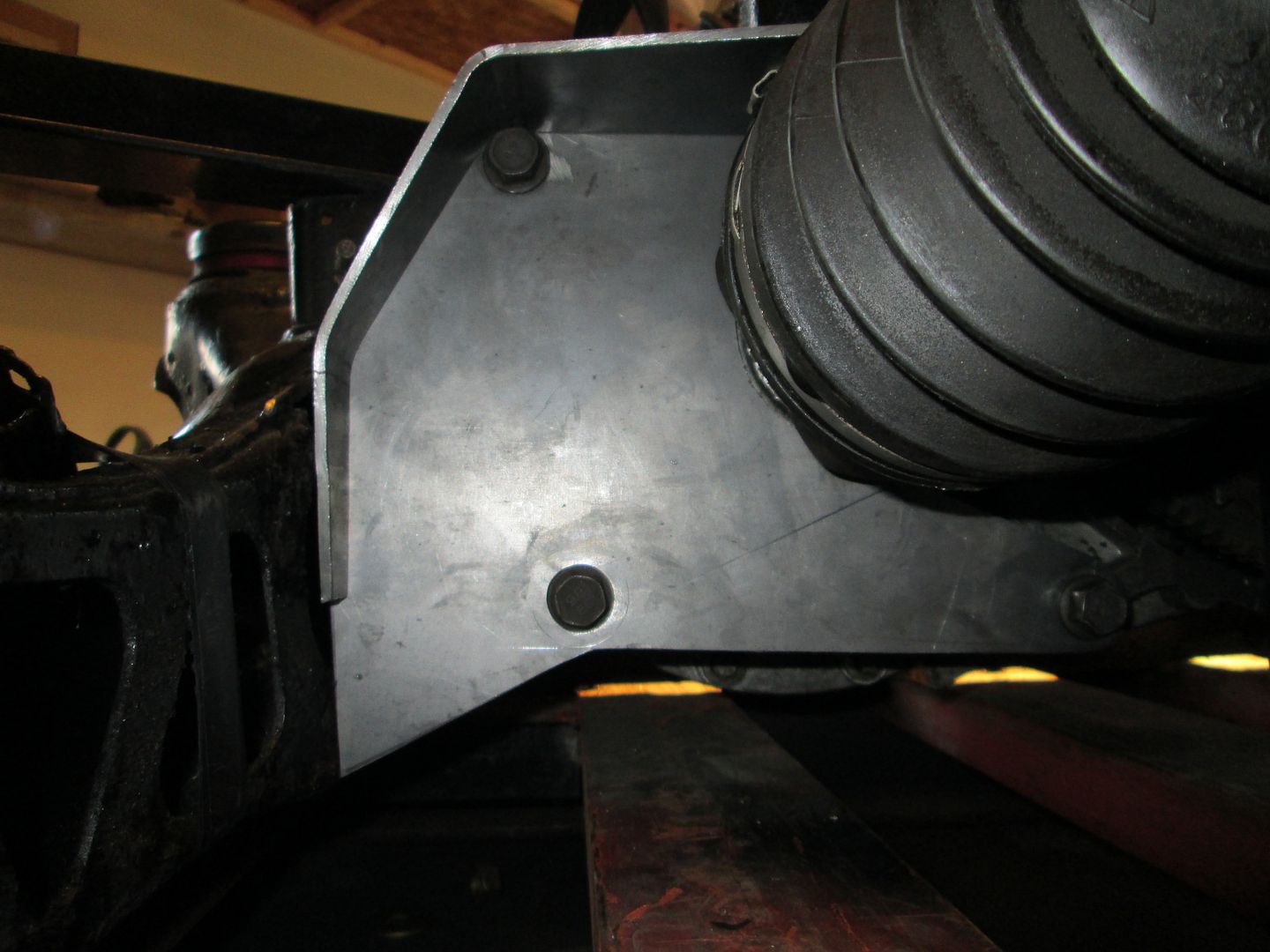
Installed:
I mentioned earlier that I wanted the drivetrain to be removable to the PS of the cradle, so if this bracket was welded to the cradle, that wouldn't happen. So that's not the plan. On the left side of this bracket will be another plate that will be welded to the cradle and bolted to this rear bracket. That will keep the direction of removal correct and allow this bracket to stay with the engine/transmission during removal.
Here is a picture of a previous mount I made like this (you can see this one also had another mount on the other side of the differential as well):
The rear mount is nearly complete. In this picture you will see I drilled the 3 holes that will bolt this bracket to the cradle and I extended the small leg down to the end of the plate:
When I had snapped an axle last year, CowsPatoot had tried to replace both axles for me. The broken one (driver side) popped out without any issues, but the passenger side would not pop. He wedged a pry bar in there and I laid on the ground and leveraged my legs against it, and it still didn't come out.
I noticed in some of the pics that it looked like you had gotten the driver side axle pulled, but the passenger side is still in - did you have issues removing it as well? Or did you not need to pull both sides so didn't?
Just wondering if there's a magic trick that we missed.
Yeah, the passenger axle is being stubborn and doesn't want to come out. So far I haven't "needed" it removed, but I will try a few more times to get it removed.
If there's any concern or possibility that the teeth on the axle have started to 'strip' trying to jump a notch in the transmission.. I'm almost worried about it coming out, we might discover that the transmission might need to be repaired/replaced.
I have no idea how likely that is, but if the axle is supposed to come out rather easily, the only thing I can think of is that the teeth are (or starting to get) jammed up.
So... I guess don't try too hard to get it to come out. lol
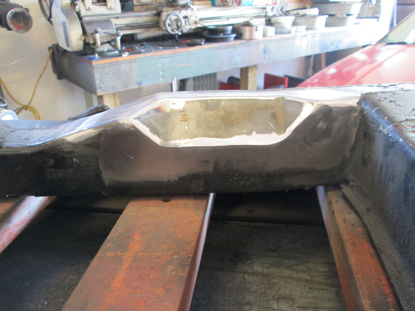
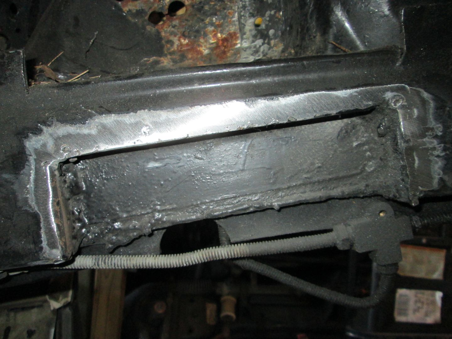
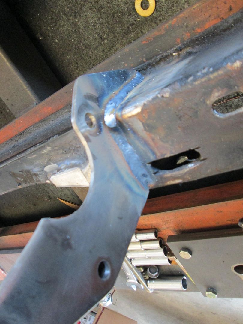
This evening, I went and capped off the notches I made in the cradle for clearance:
Then I added a piece of 1/8" steel to the rear cross member to replace the section that was previously cut out. The tab for the rear transmission mount bracket will be welded to this new plate.
On Saturday, I need to go pick up another tank of shielding gas, fab up the rear weld on mount bracket, and weld the inside of the side cradle notch around the suspension box. Then with the mounts tack welded into place, I will do another test fit to confirm placement/fitment and then weld the mounts solid to the cradle.
As I got ready for another test fit, I went ahead and cleaned up the weld from the original frame notch. When I checked for belt fitment last, it was hitting on some excess weld slag, so I wanted it smooth for this test fit.
Then it was in for the test fit. Both ends of the intake are 10 1/2" from the rear firewall and the belt now clears (I shifted the drivetrain about 3/16" to the driver side from the last test fit):
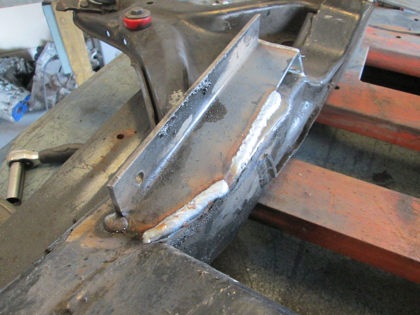
Then it was out again for welding and to finish the mounts. Unfortunately, I didn't get to the weld shop this morning, so I ran out of gas once the mounts were tacked into place. Here is the rear support for the angle that is hanging over the cradle:
Here is the tab for the rear transmission mount. This will be welded to the cradle:
I was able to put a full section of weld on the front mount and a section of the angle to lock the drivetrain in place:
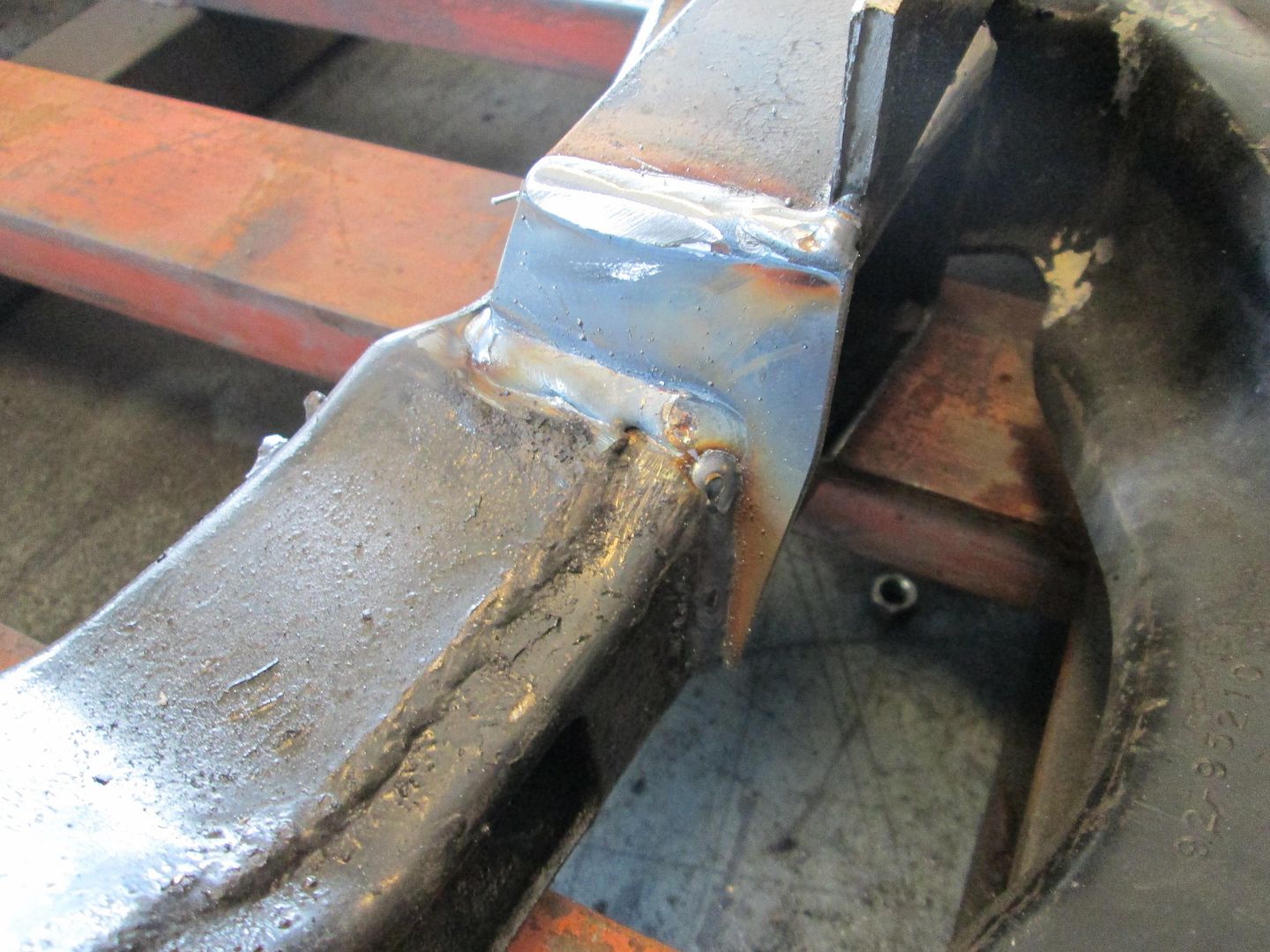
Both girls are back in gymnastics on Monday night, so not much will happen on Monday. I did manage to get another tank of shielding gas, so this evening I was able to finish the welding on the mounts:
The rear bracket had another piece of steel tacked to it and the cradle to resist the pulling that the weld would have. Once the welding was done and everything was cool, I cut it back off and smoothed everything back out.
Now the engine/transmission have finished mounts!
Now I need to separate the engine/transmission and work on the starter/oil filter relocation.
The benefits of restarting a browser. Things are appearing normally now. Thanks for the update!!
Looks pretty damn awesome. Hyped that you've got some ideas for the starter. It gave CowsPatoot and L67/EMC209i a little trouble because it could shift every-so-slightly on it's shims when being torqued down, and then be off enough to be incompatible.
Looking forward to what you cook up with that relocation and starter!
[This message has been edited by Trinten (edited 08-27-2013).]
Between brake work for others and prepping the my LS4/F40 Fiero for the LS Fest... hadn't made much progress on Vince's swap till today.
The starter setup on this car was pretty sad... The Archie kit uses a bolt on block that holds the starter (not really the issue here) and this car had the flywheel turned down to accept a 142 tooth ring gear vs the 153 used with the Archie kit to resolve ring gear/differential interference with the F23. So the starter block was modified to allow the starter to go in further through a combination of slotting holes and adding shims... end result is a very difficult setup to adjust and replace while keeping the proper gear mesh and all the spacers allows the starter to flex more than I think it should.
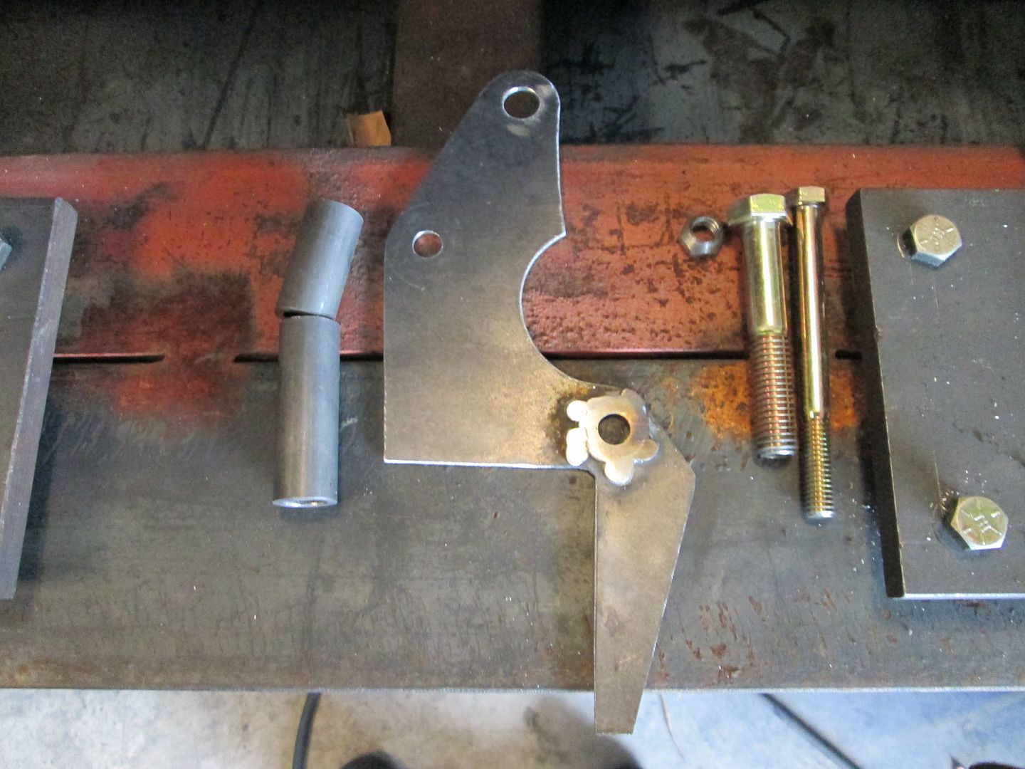
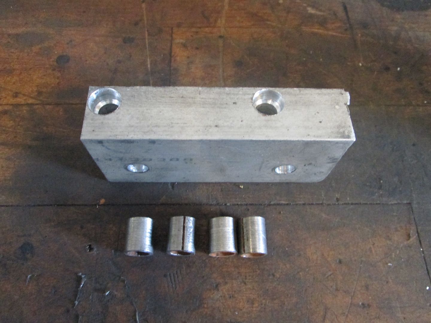
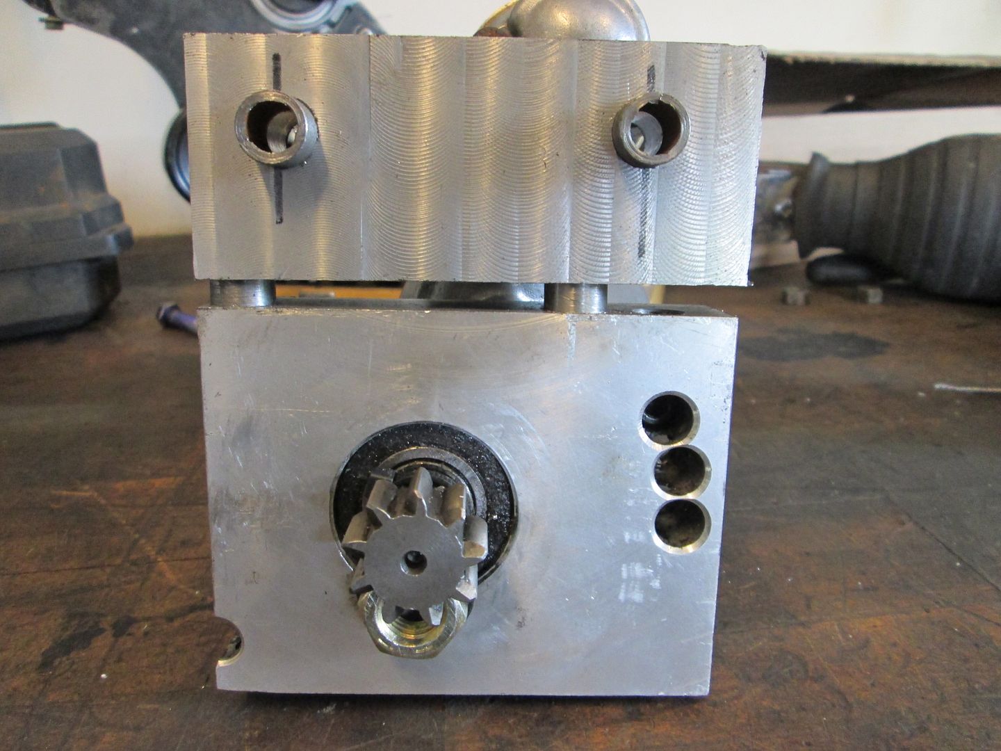
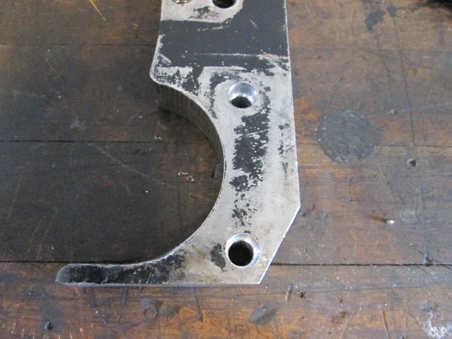
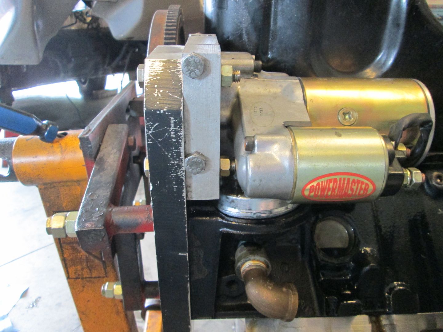
First order of business was to make a new starter mounting block. I happened to have some aluminum bar on the shelf that was slightly thicker than the starter plate on the starter, so it was cut to the right length. Then I placed it along the face of the starter making sure the face was flush, then transferred the bolt holes and drilled the first set of hole in the block. Then bolted the plate to the starter and clamped it to the adapter plate with the gear properly meshed, transferred the second set of holes, then drilled them. Put it back together and everything looked good.
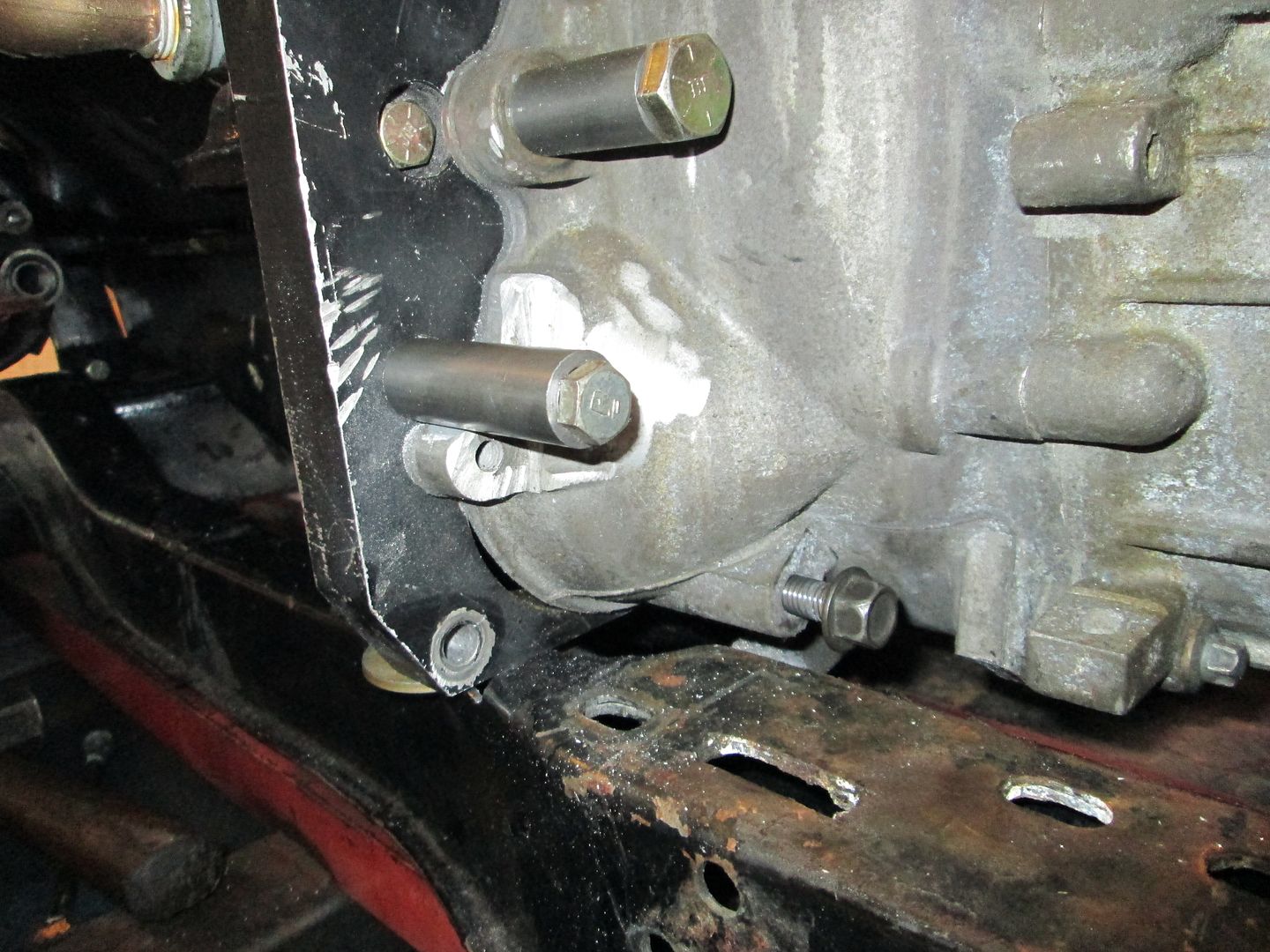
Now most would have stopped right there (and many do stop right there when installing a SBC using an Archie kit), but the next time the starter comes out while the engine is in the car is going to be a chore to get it realigned because there just is too much available slop in the holes and access/visibility to the teeth mesh is very poor with the engine installed in the car.
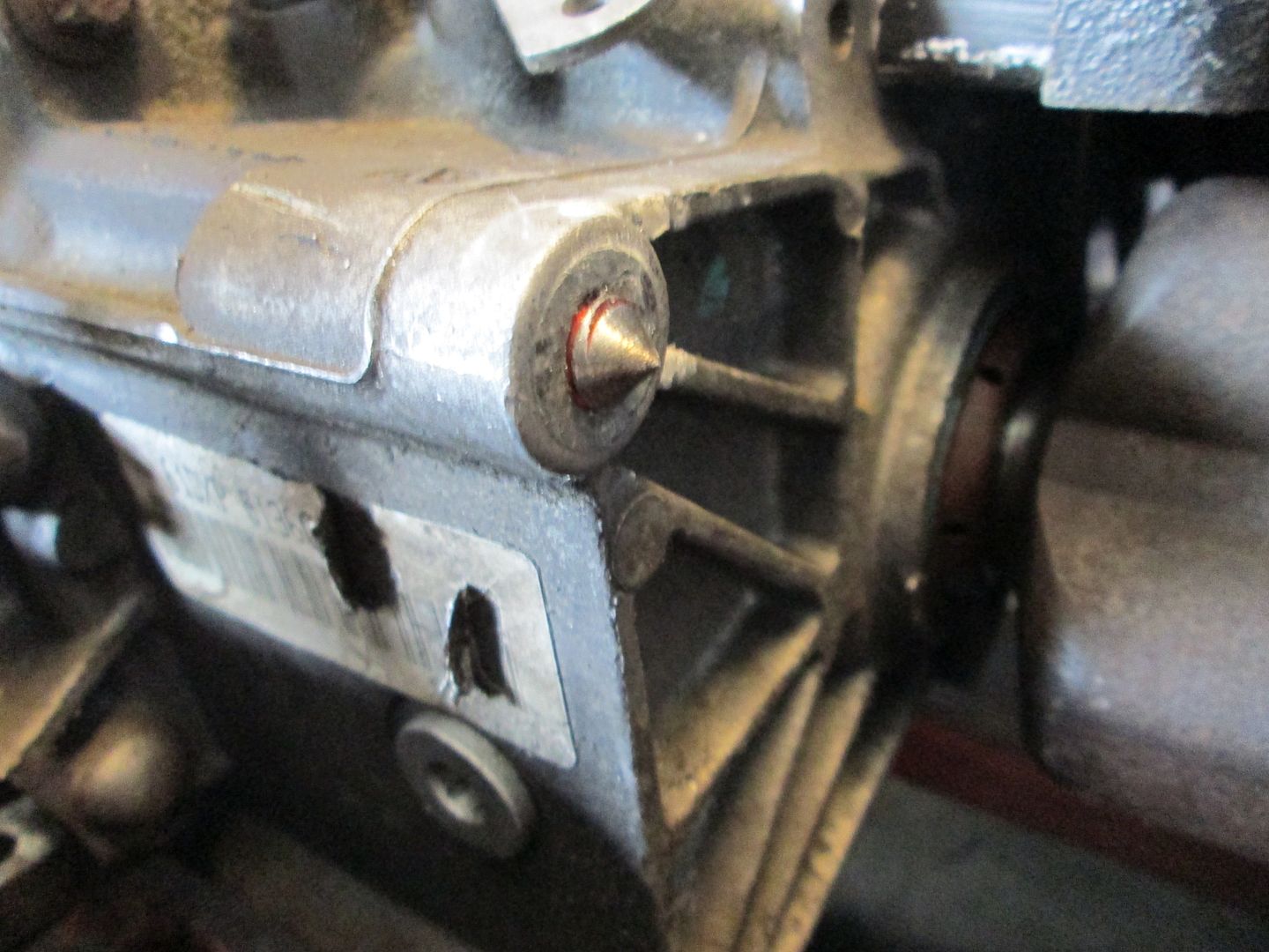
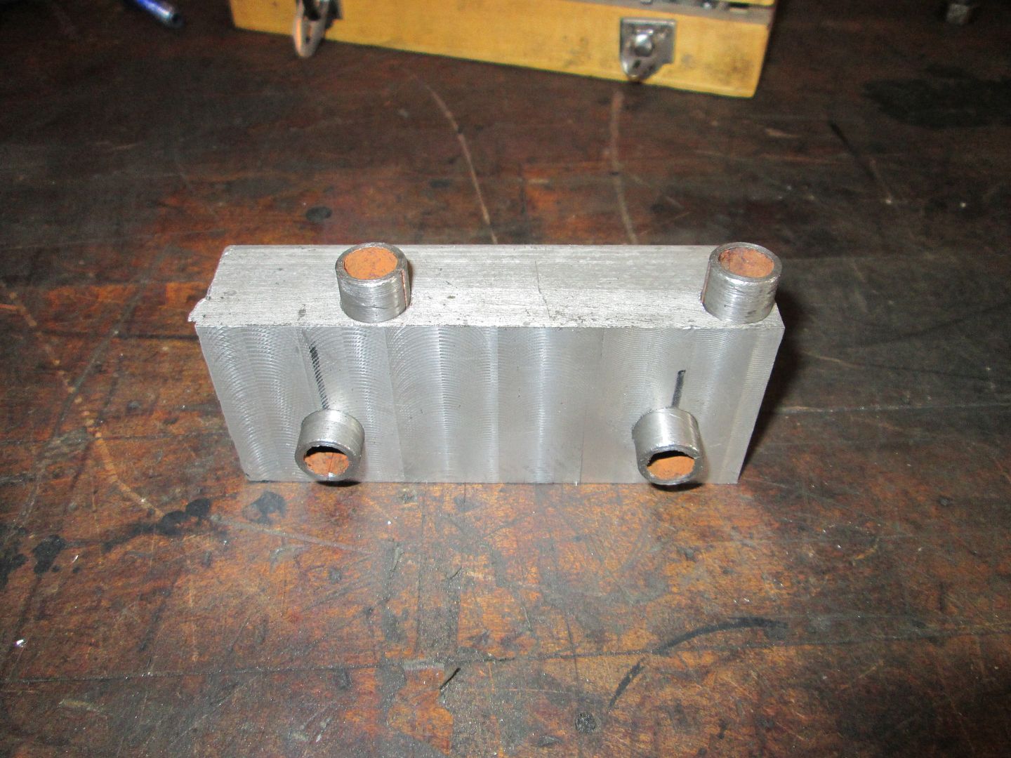
So in this picture you can see that I counter bored all the holes in the starter block (as well as the starter plate and the adapter) to accept some 1/2" OD dowel pins (cut down from sway bar end link spacer). These pins and bores will ensure a snug starter fit w/o any visible slop, so the starter can be removed multiple times and always put back in with easy and precise alignment.
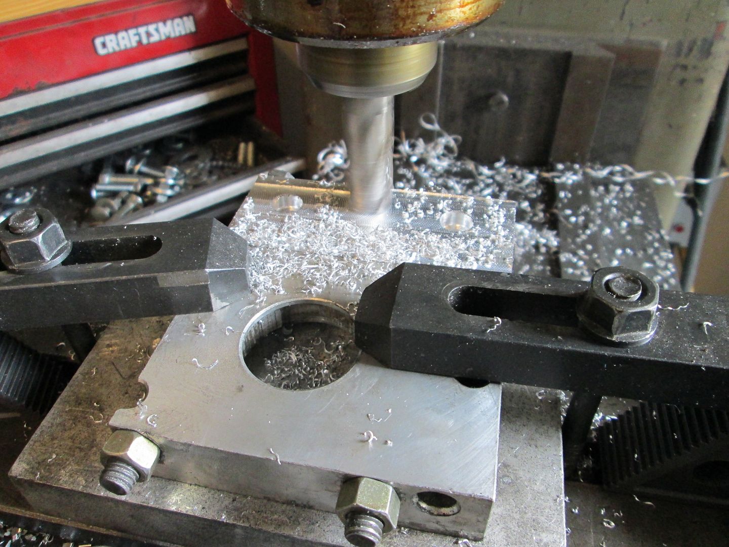
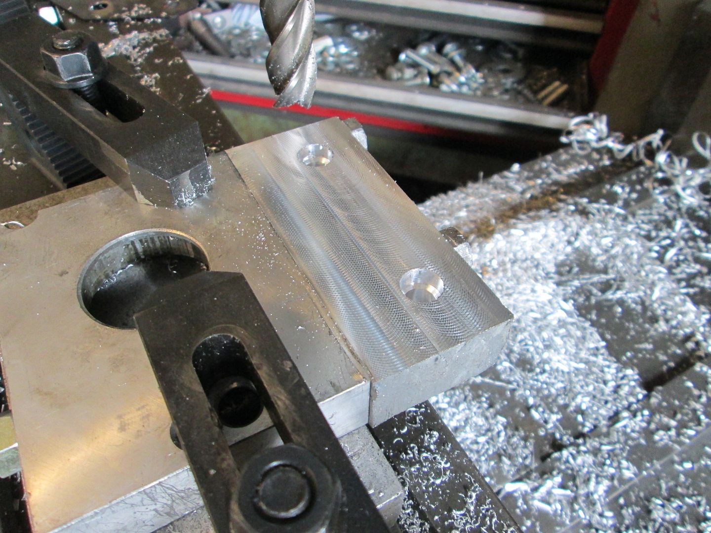
After a test fit with the dowels in place, the mounting plate was proud of the starter mount face, so I put it in the mill to make them flush and parallel:
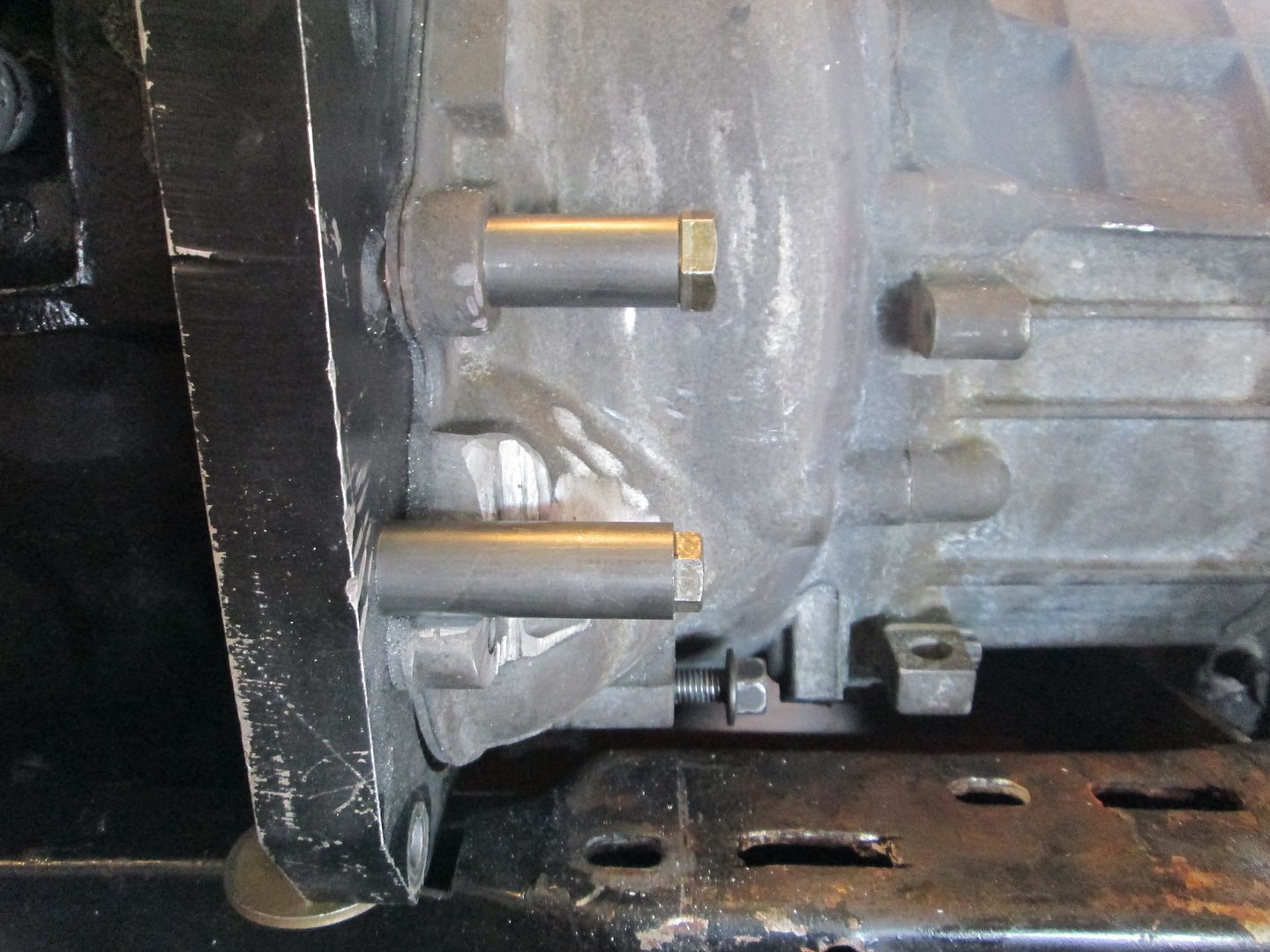
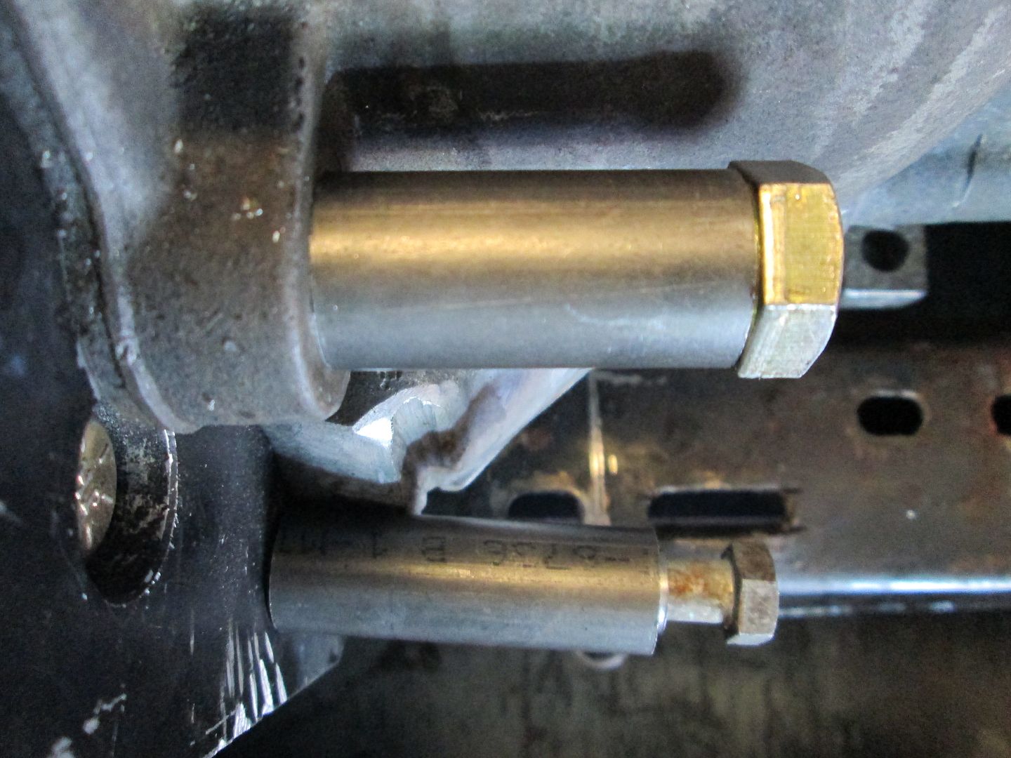
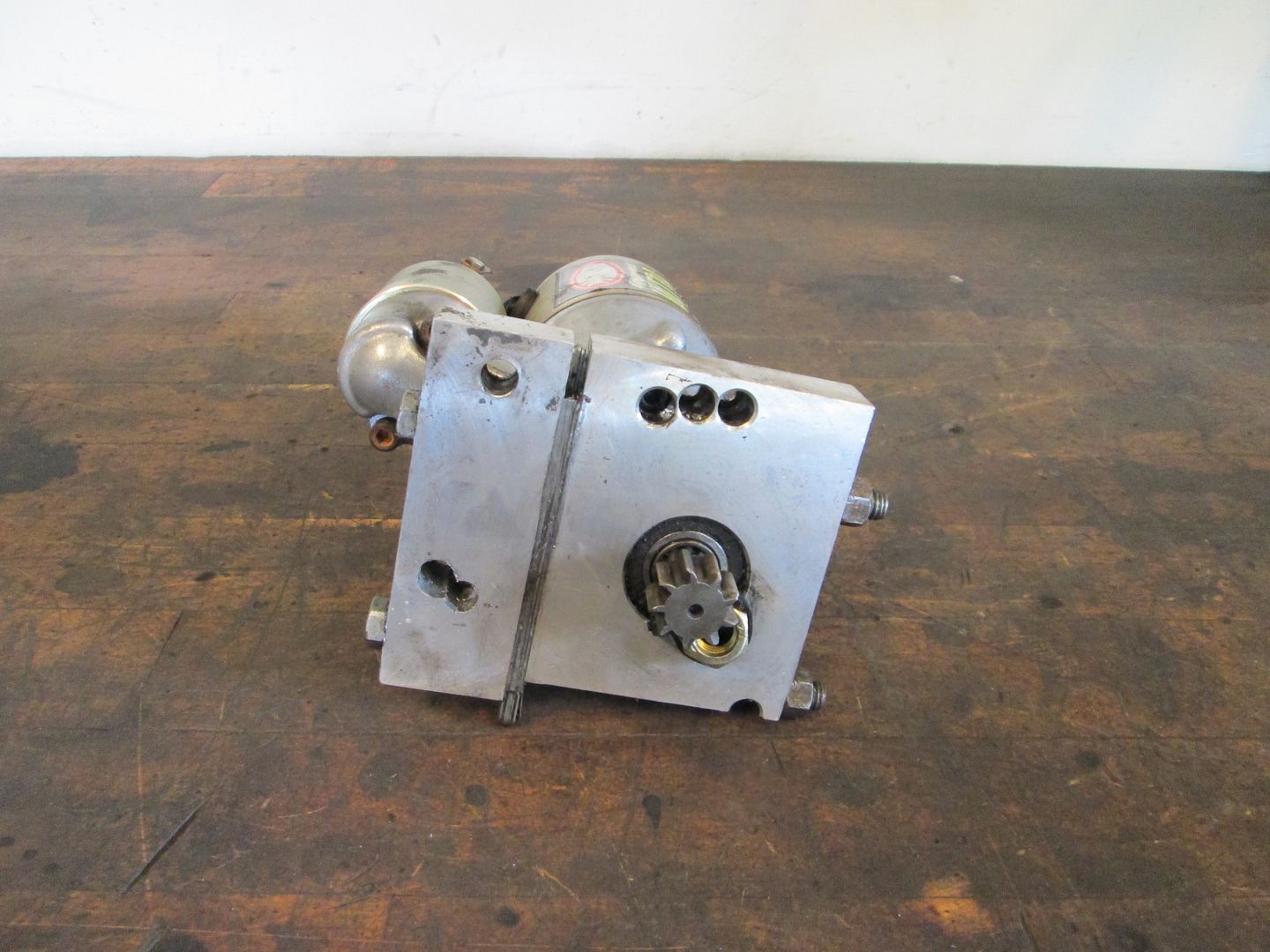
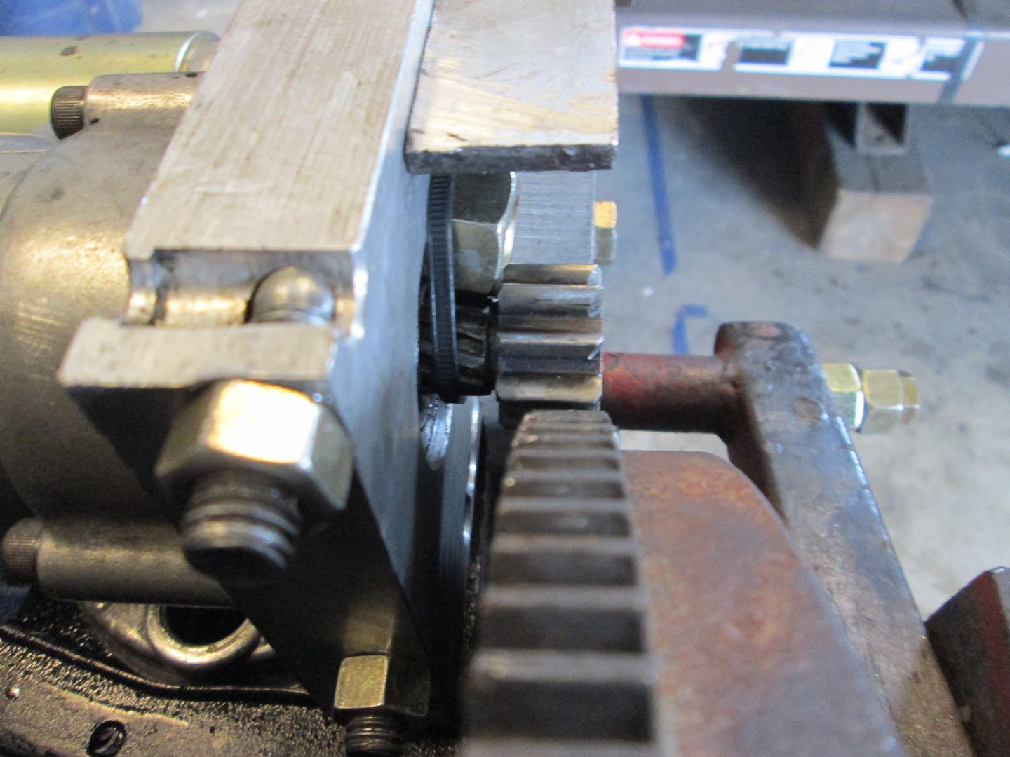
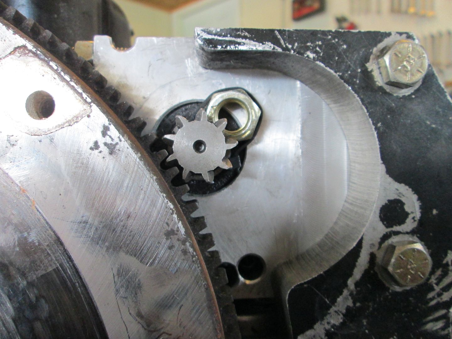
Here are some pictures of the starter installation with the new block and the dowel pins (notice the trick of using a wire tie and a 1/2 nut to keep the gear extended):
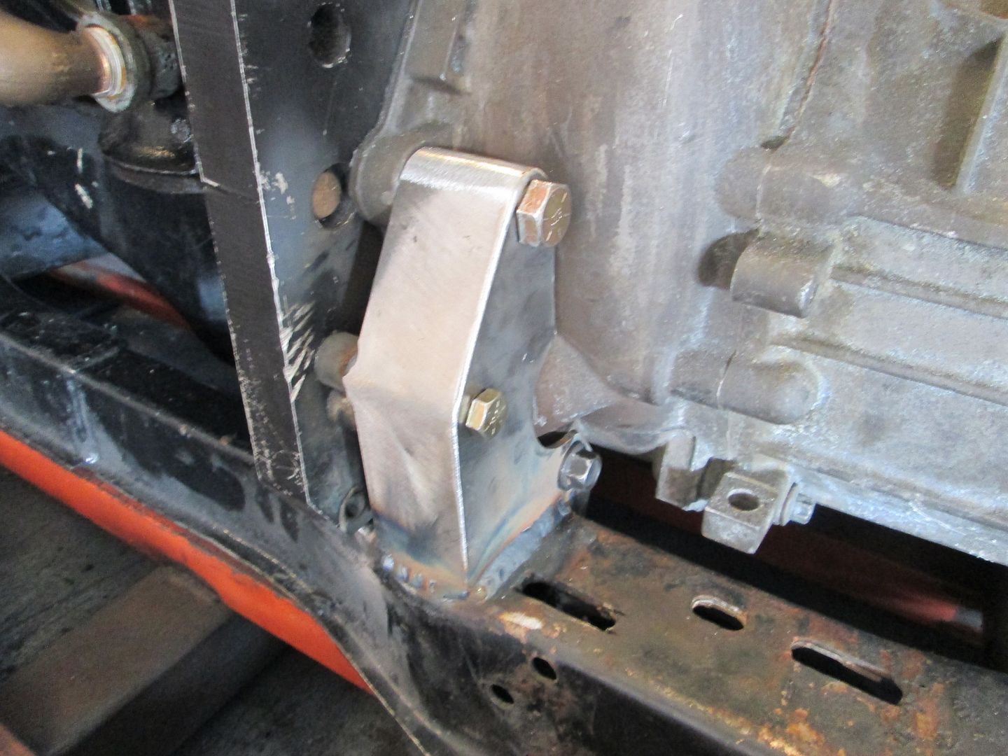
Now the only issue with this starter placement is I will have to make another slight notch in the front cradle crossmember as the starter block hangs down lower than the bottom of the adapter and the bottom of the adapter clears the cradle by 1/16". There really wasn't much option with the starter placement as the crossing bolts in the starter block and the front cradle rail really limit options. When I made the new block, I did make sure the crisscrossing bolts in the new block were as close to each other as possible.
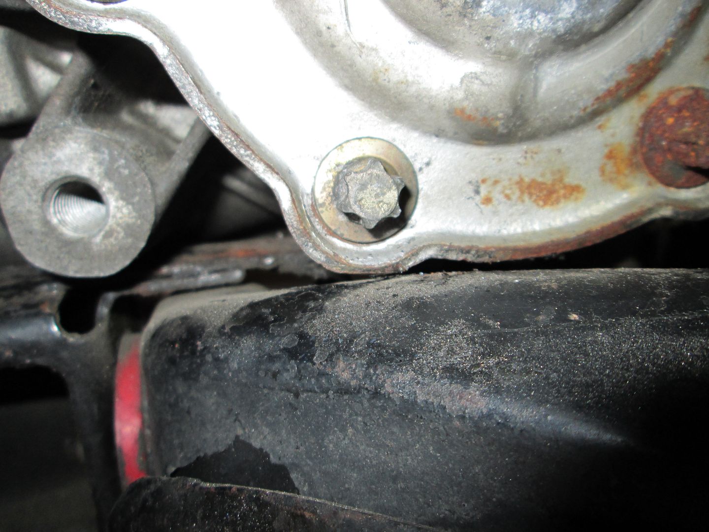
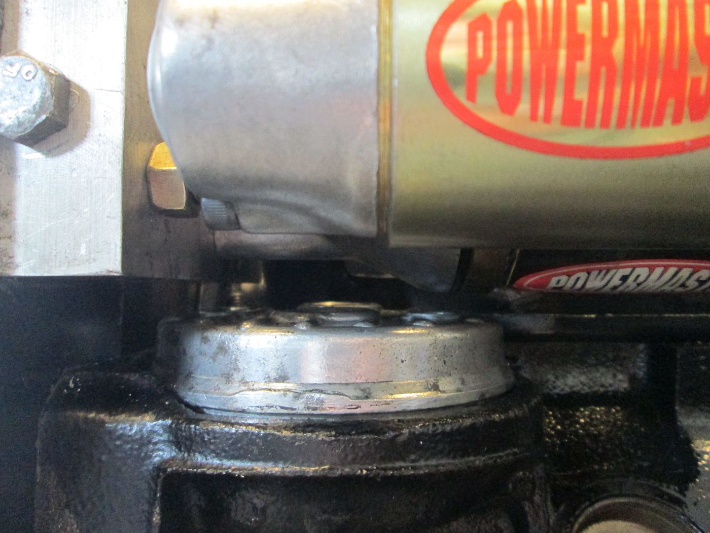
Here is a picture of the clearance between the starter and the oil relocation plate:
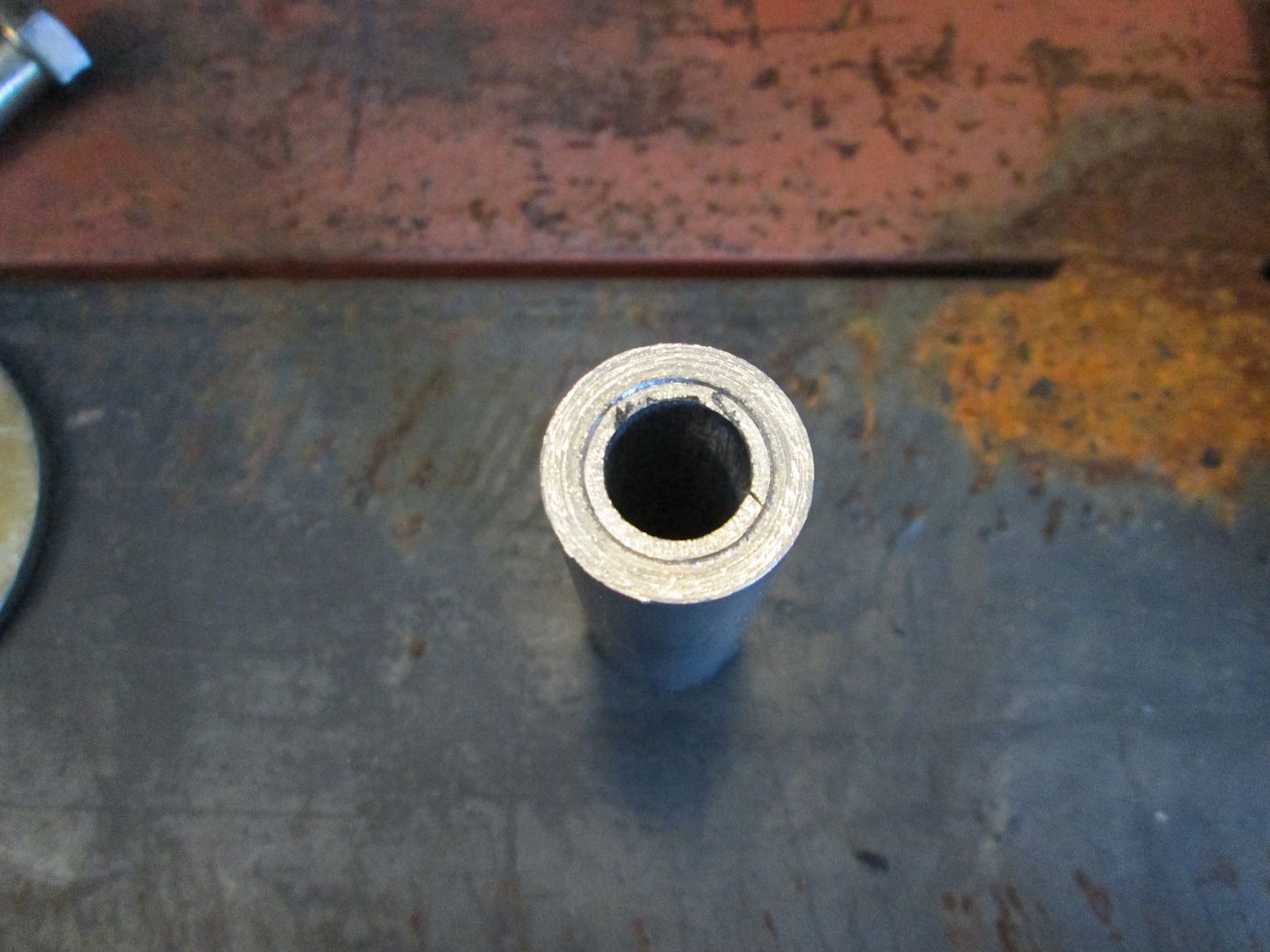
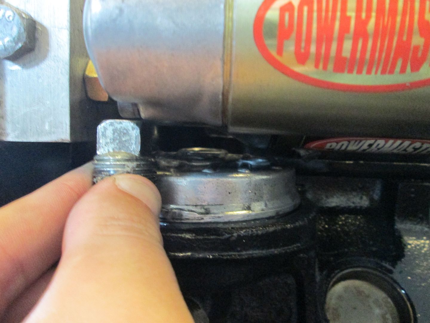
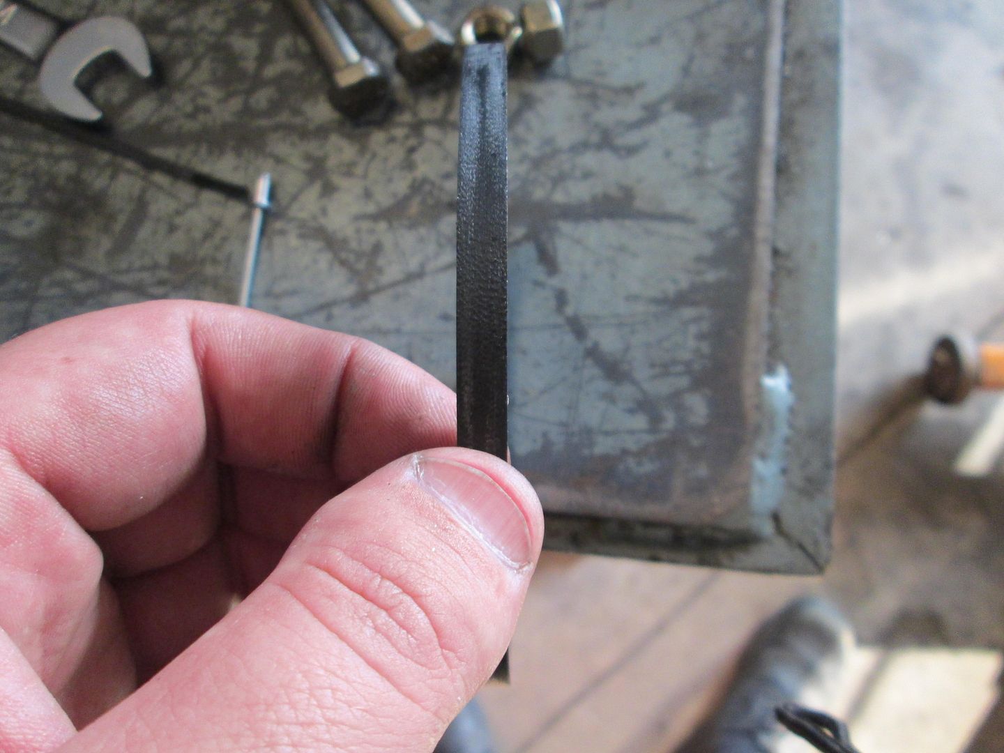
The center port gets capped off because there just isn't room in there for anything. As part of the original install, a tall pipe cap was used. This was too tall, so I replaced it with a flush cap and a recess for the allen wrench.
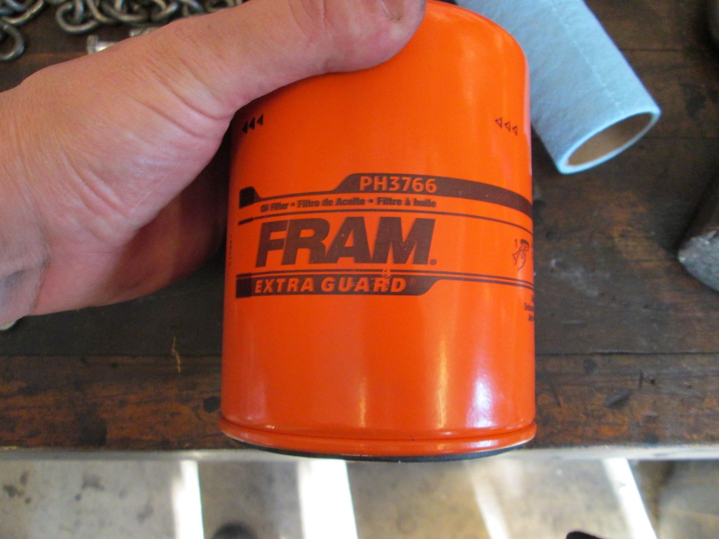
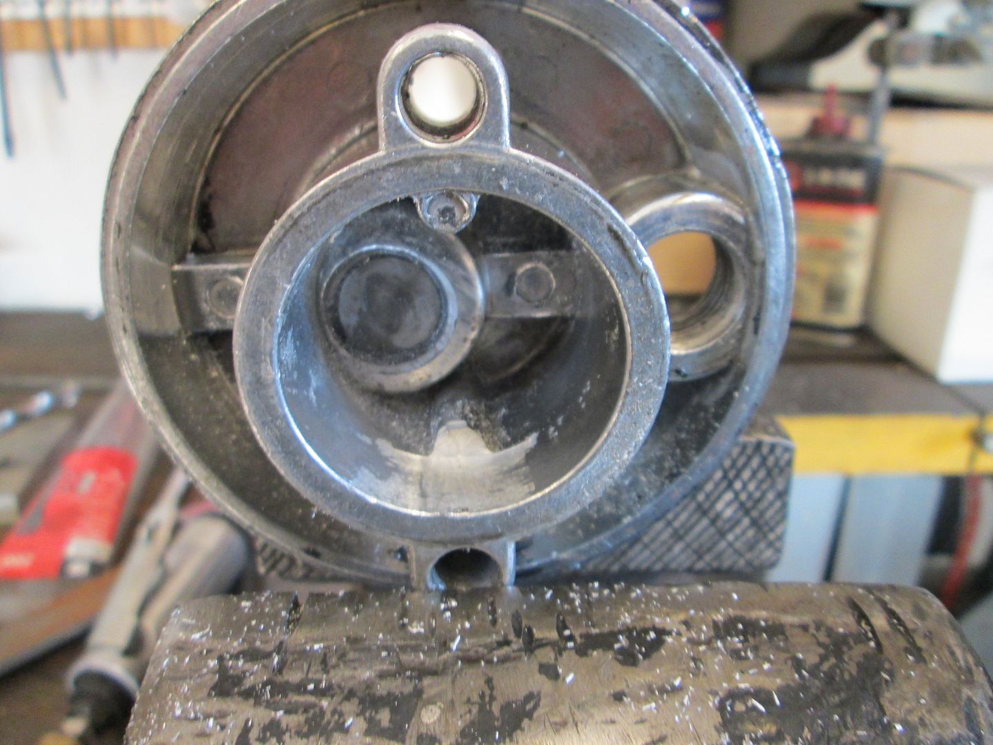
I also started working on the oil filter bypass... these things nearly always leak because its hard to get a good gasket for them. Since it is an oil bypass, I like to use oil filter o-ring gaskets. Here is the one I use, don't know the original application:
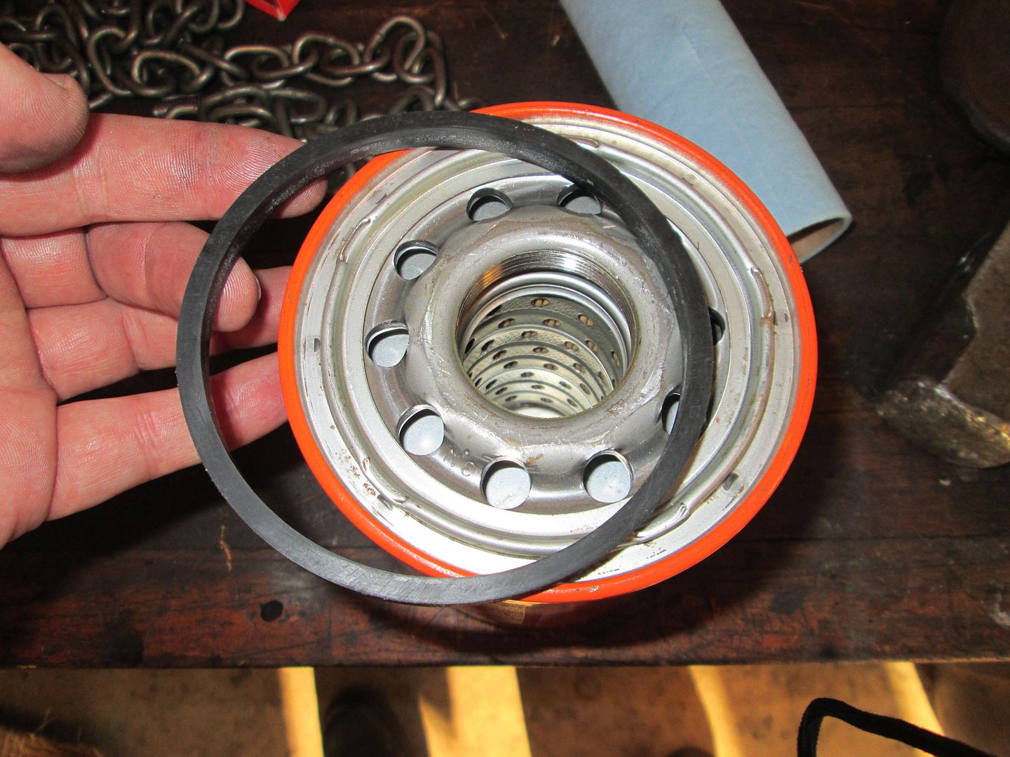
It is the perfect OD to fit in the machined pocket for the oil filter:
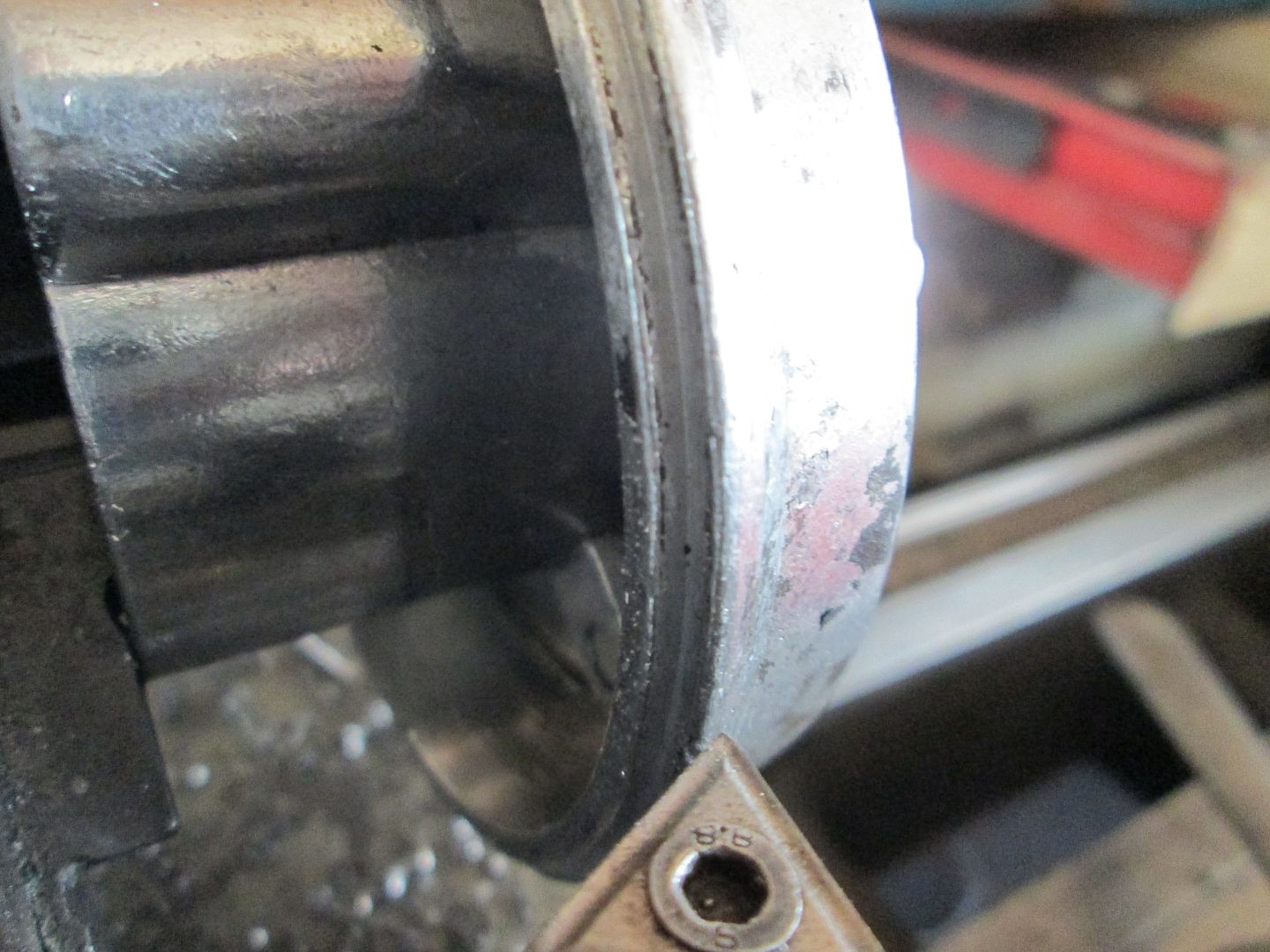
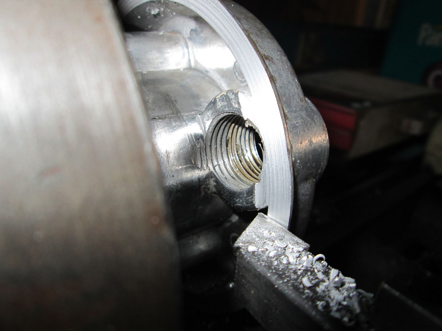
Its about 1/4" thick, which is a little too thick for use without modifying the relocation housing:
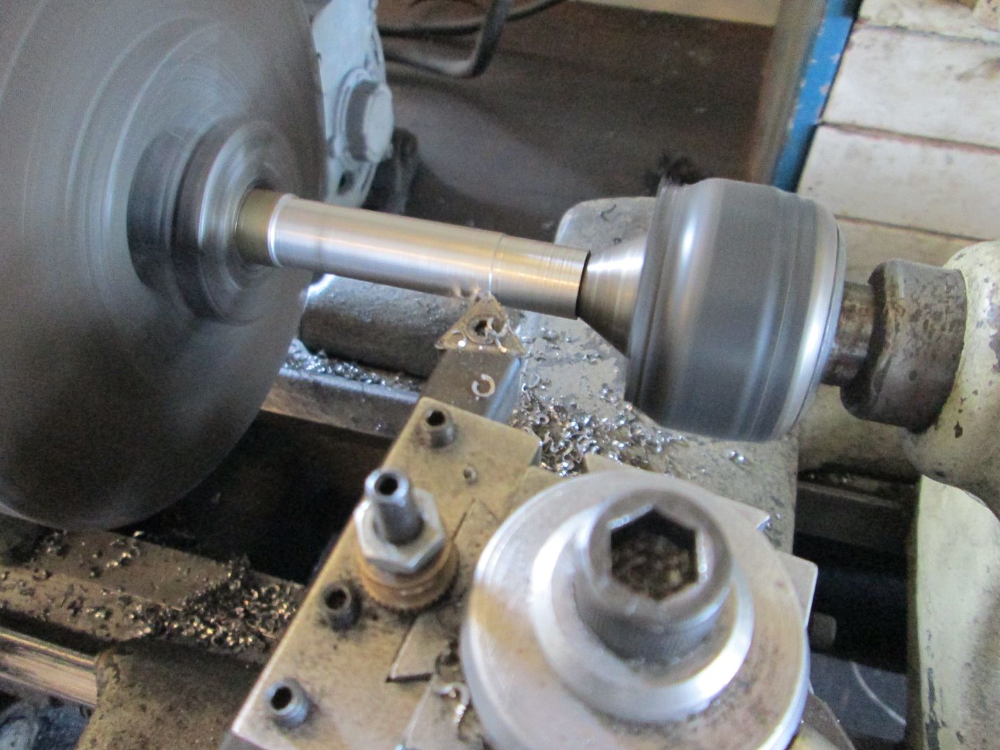
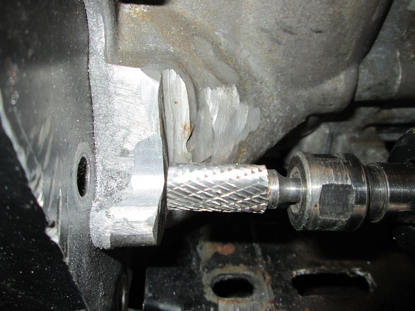
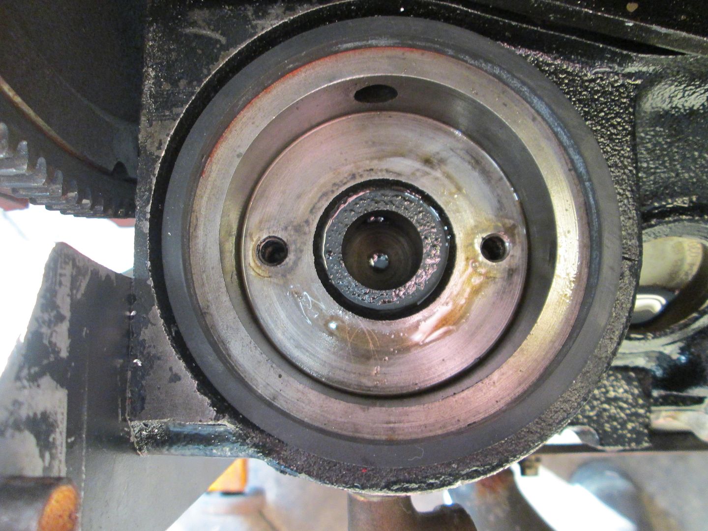
I needed to chuck up the relocation housing in the lathe, but to do so I have to remove one of the casting ports with an air grinder with burr tool.
Then chuck it up in the lathe to remove the groove at the sealing surface to make more room for the seal. Here is the stock seal surface:
Originally posted by fieroguru: These pins and bores will ensure a snug starter fit w/o any visible slop, so the starter can be removed multiple times and always put back in with easy and precise alignment.


 Topic Closed