So managed to finally finagle Summit Racing's website to only show me resonated tips, and only two were under the length that FieroGuru gave me. It's still options!
With all of the awesome tricks he's got planned for it, I think I'll see if he can see what the volume comes down to, and if there's any resonating in the cabin at any particular speeds before he needs the tips.
Here are the two tips that have resonators and are under the 10.5 inch limit:
And there is those C6 tips, though the inlet is a little smaller than 2.5", so if that's going to be a pain in the ass for FieroGuru to weld on, I'll skip those. Inlet ID = 1 7/8"
If the exhaust is quiet and fairly drone-less, then I'll see what other tips I might want on there.
Just my 2 cents Trinten, One of the measurements I struggled with, when choosing my tips was the 6-1/2" maximum width, at the body cut outs below the bumper.
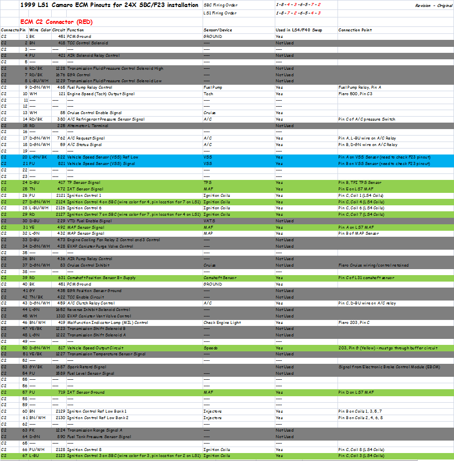
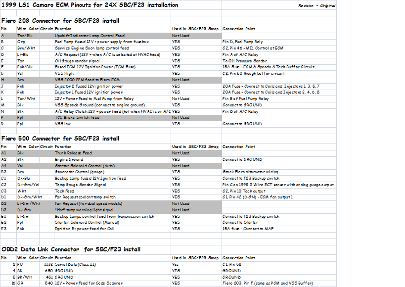
Took a break from the fabrication side and started working on documenting all the harness changes. Here are the spreadsheets I put together that will guide me through the harness build. Everything in white is wired just like stock, everything in grey isn't needed and will be removed from the harness, everything in green has something non-stock about it. There are 8 wires (coils and injectors) that need flipped due to the difference in the SBC and LS1 firing patterns, then you get into the swapped components (TPI IAC and TPS, LS7 MAF, L31 cam sensor, LT1 knock sensors, F23 VSS sensor, etc). On all these non-stock items, I had to cross-reference the wires and pin locations at the connector as almost all of them changed with the sensor changes.
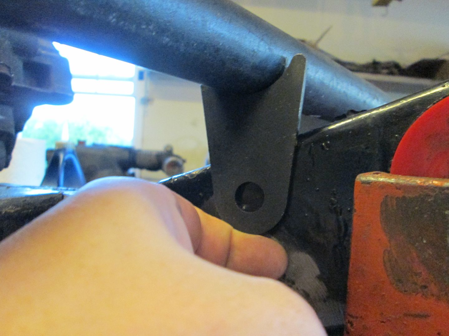
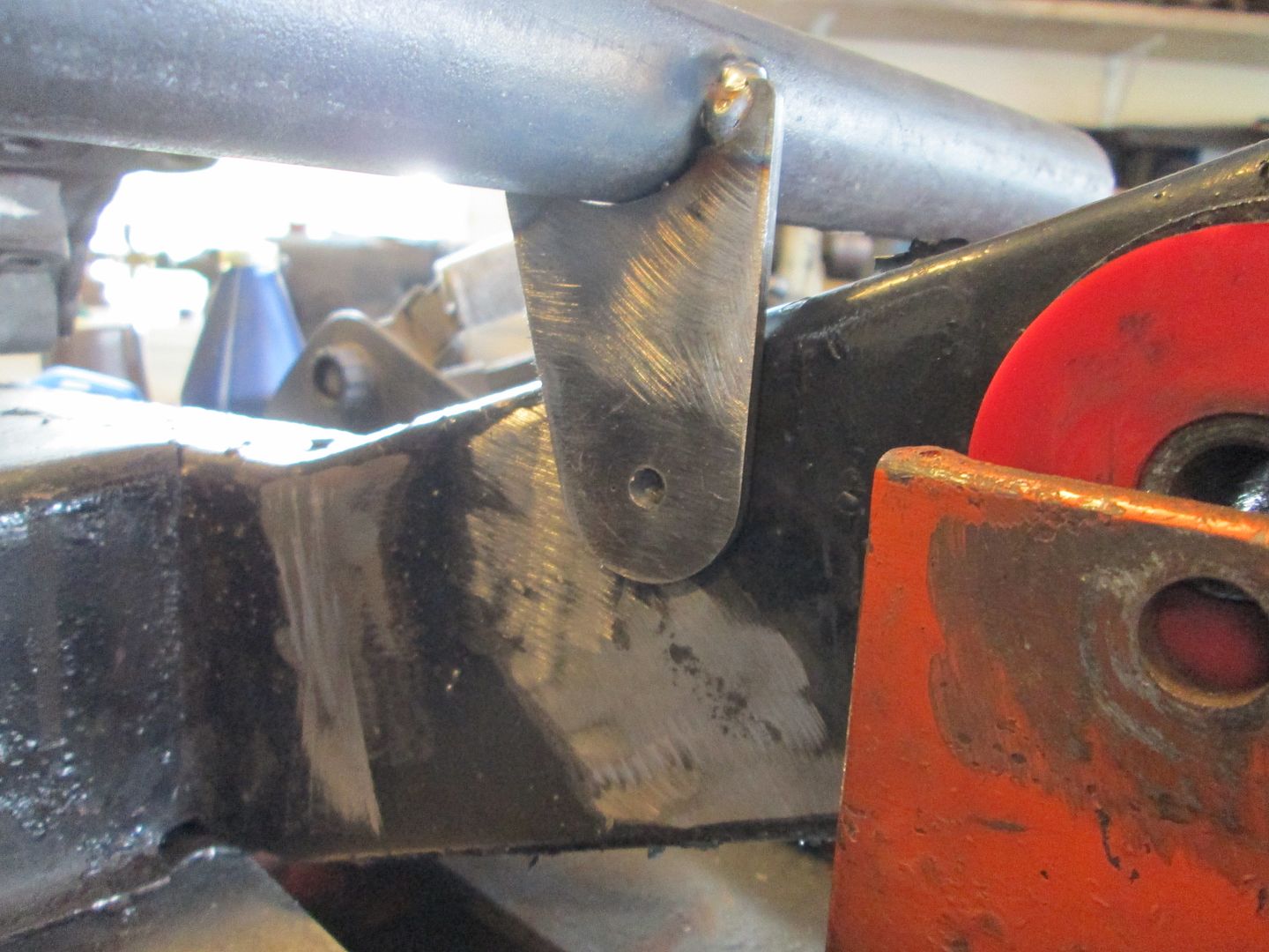
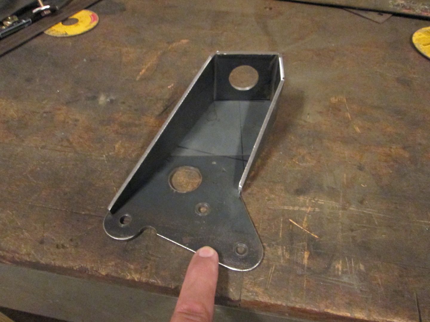
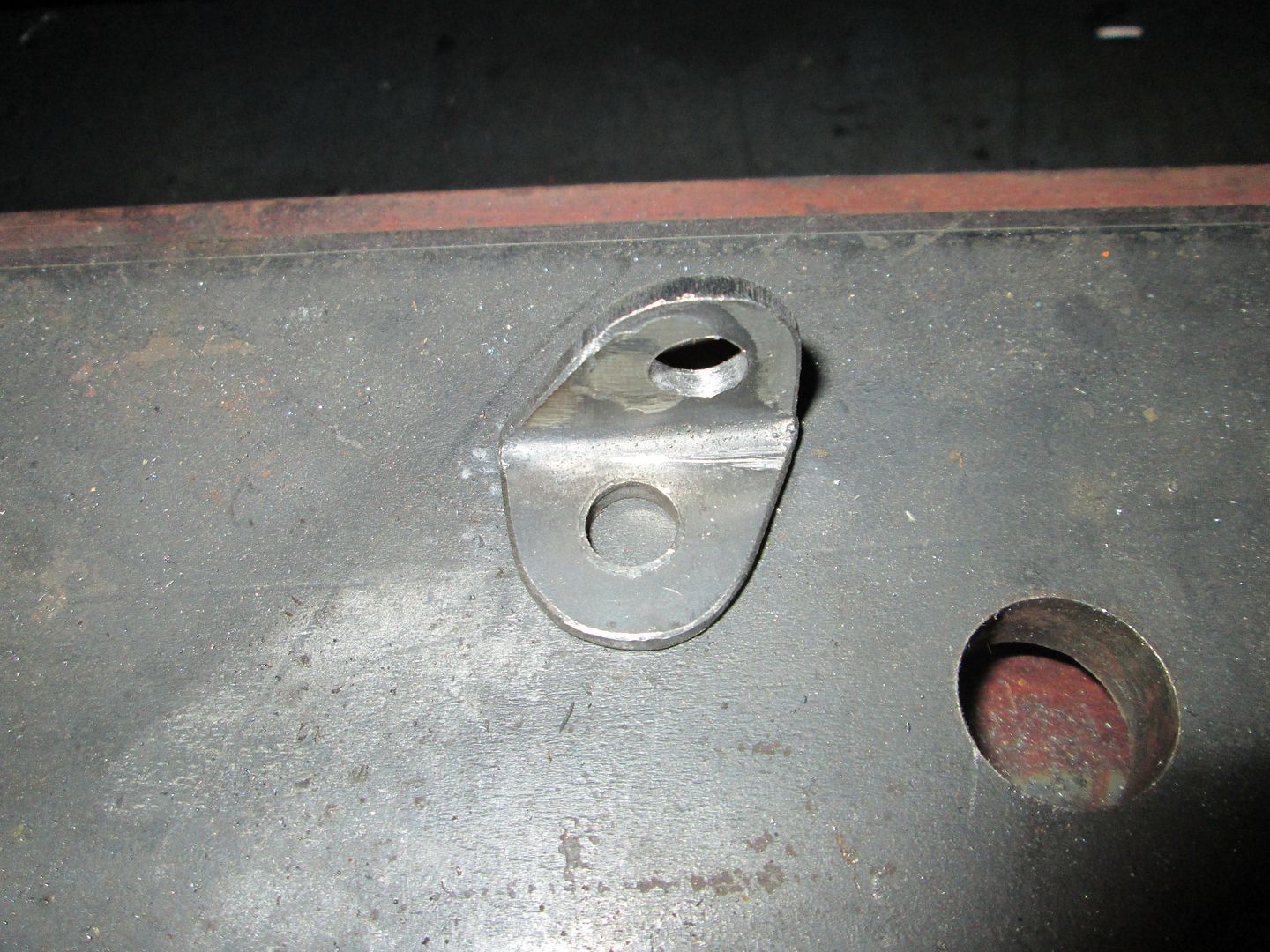
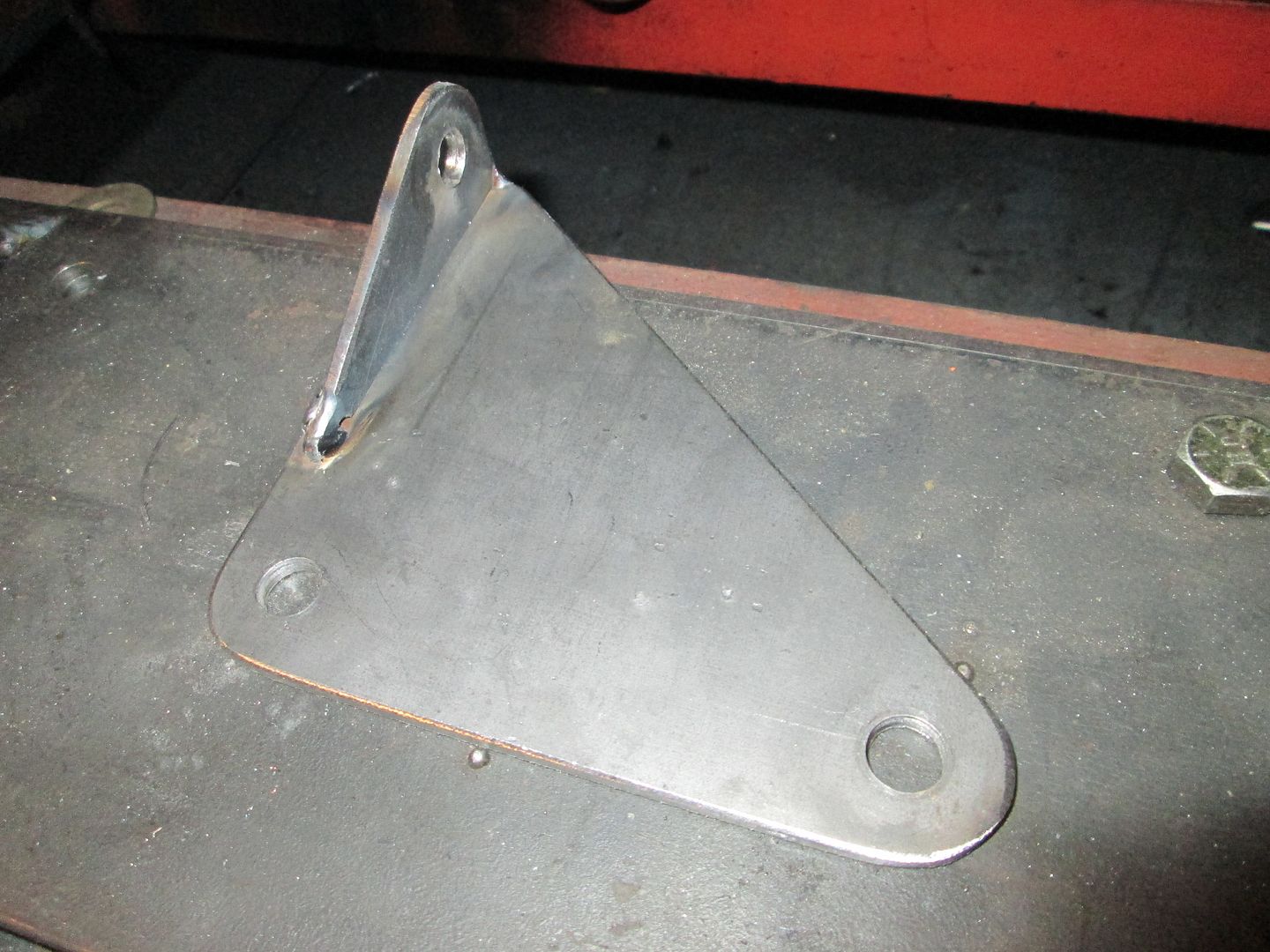
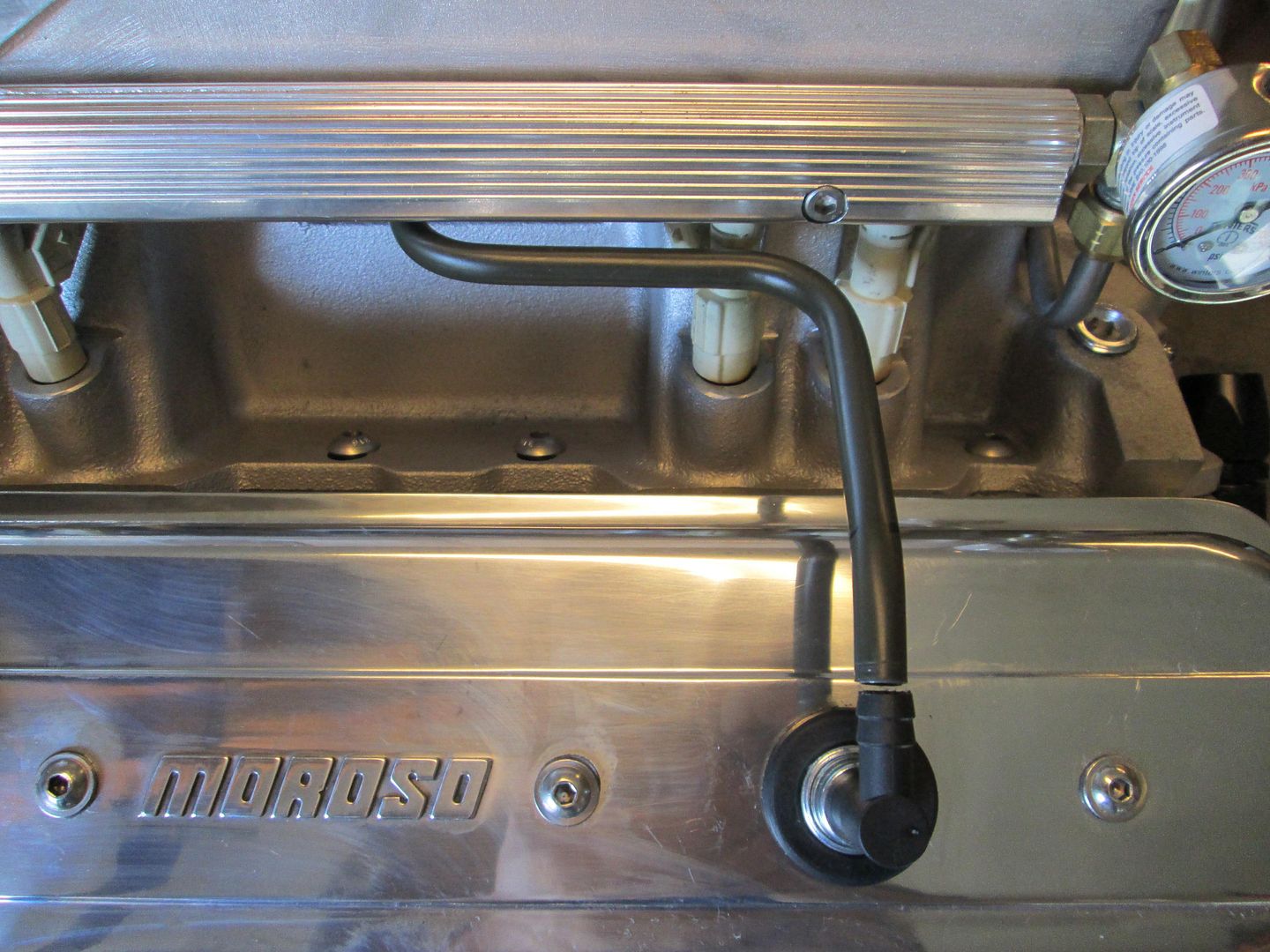
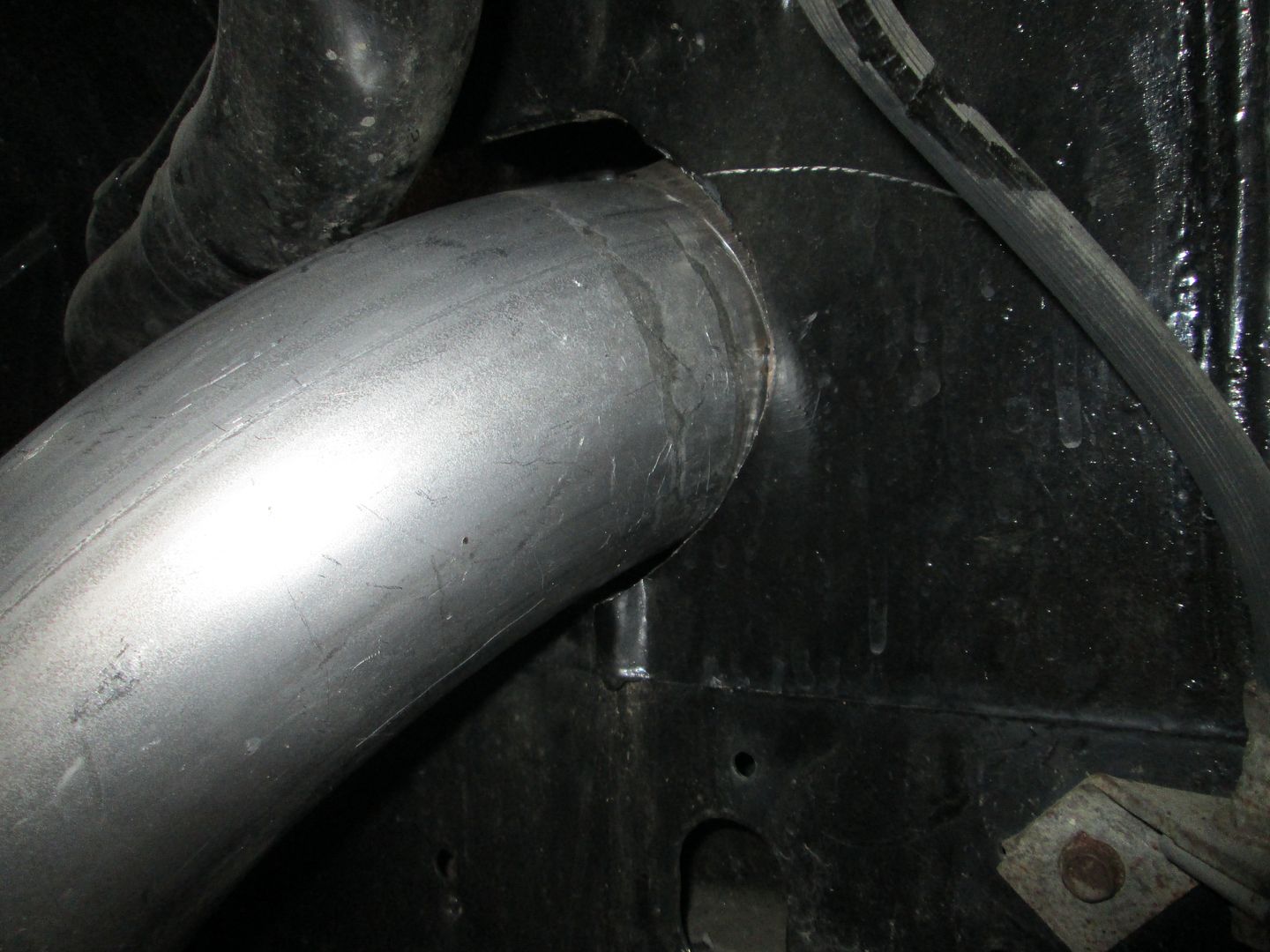
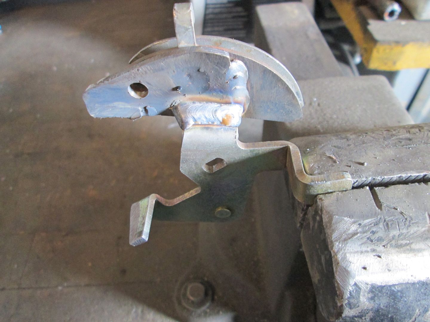
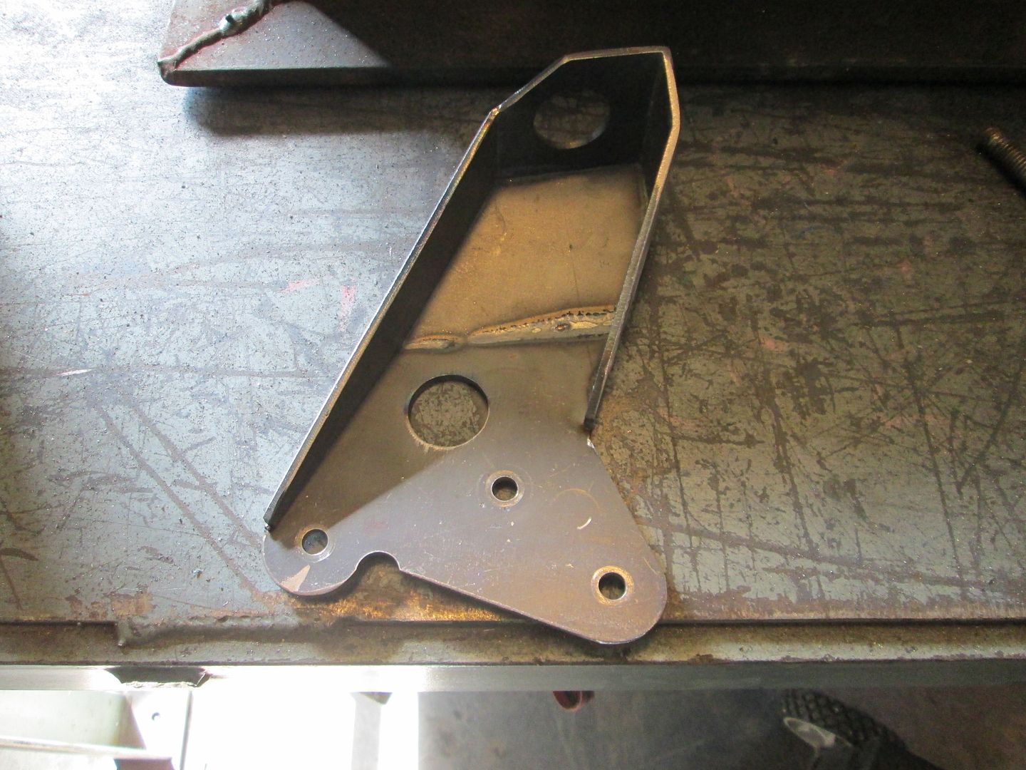
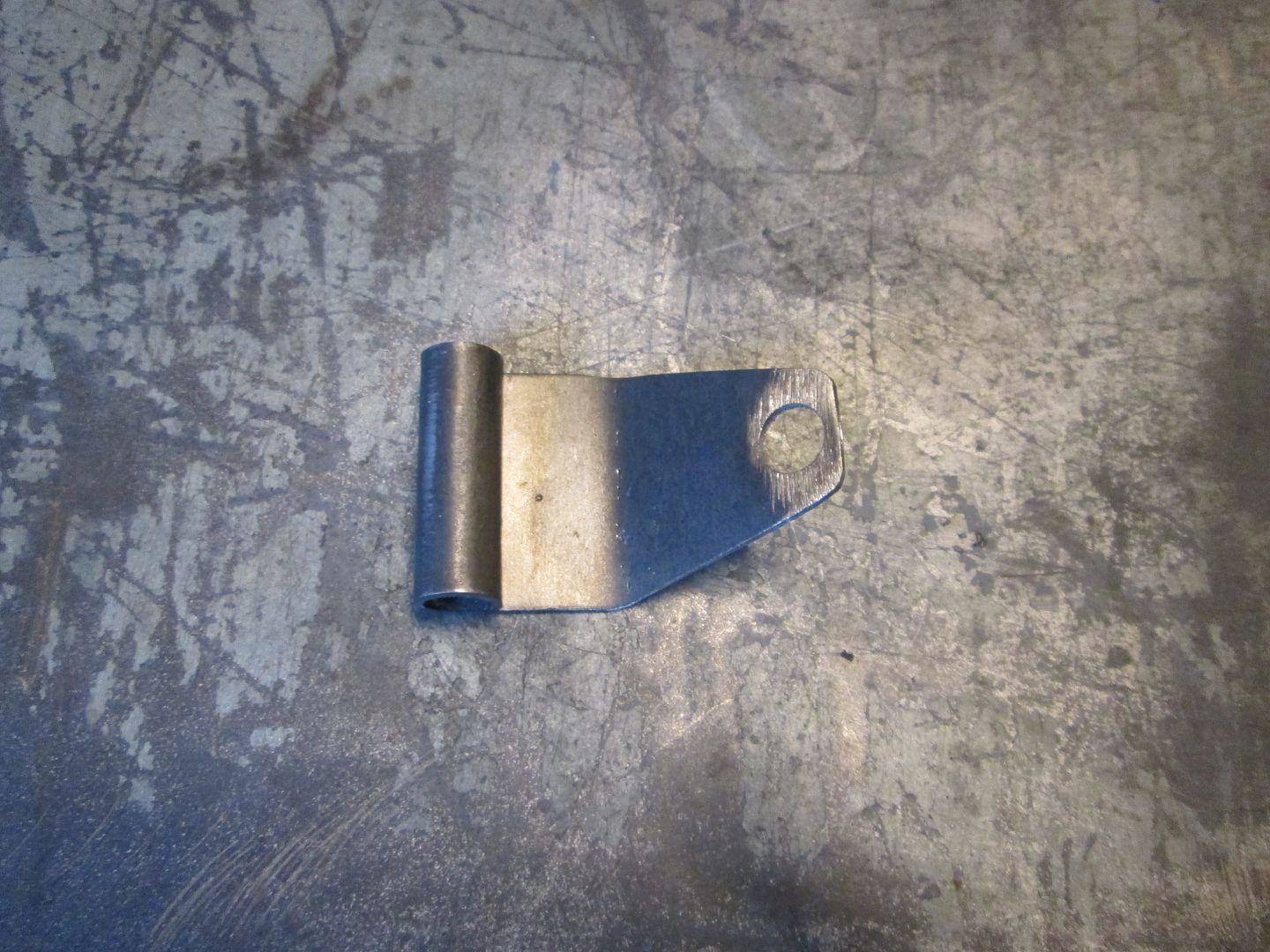
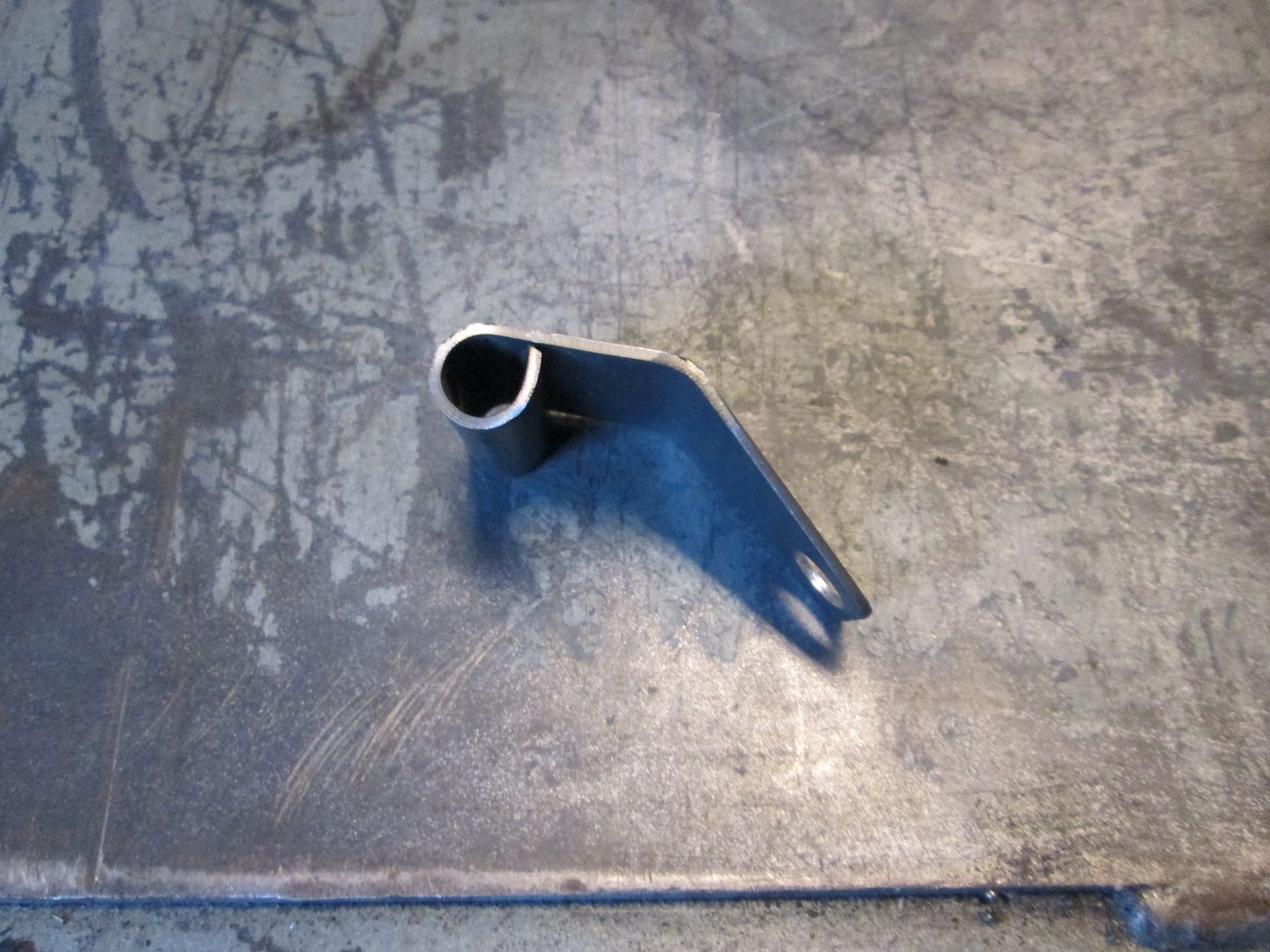
Just need to fill the hole in this bracket to make it smaller and weld it to the pipe:
Still pondering where to put the coils... Having the wires come from the bottom will keep everything hidden, but there isn't much room for the coils down there unless I put some studs in the oil pan flange and make the coil brackets hang off the oil pan. Or run the wires from the top side and mount the coils off the ends of the heads like my LS4 has them...
I don't want to steal the look you setup for yours, but it sounds like mounting it the way you setup on the LS4 will also help make it easier to route the wires away from heat sources, and reduce how much shielding you have to do - or am I misunderstanding the setup?
With the coil packs low in your first proposal, will I need to worry about water or road debris getting kicked up?
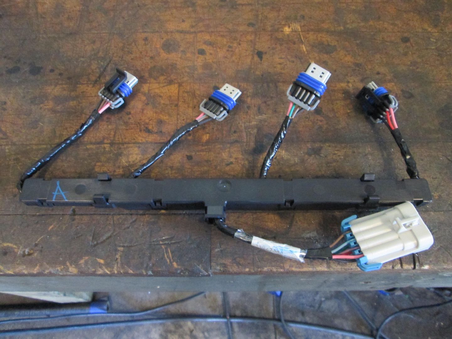
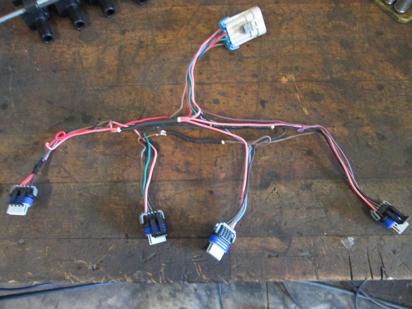
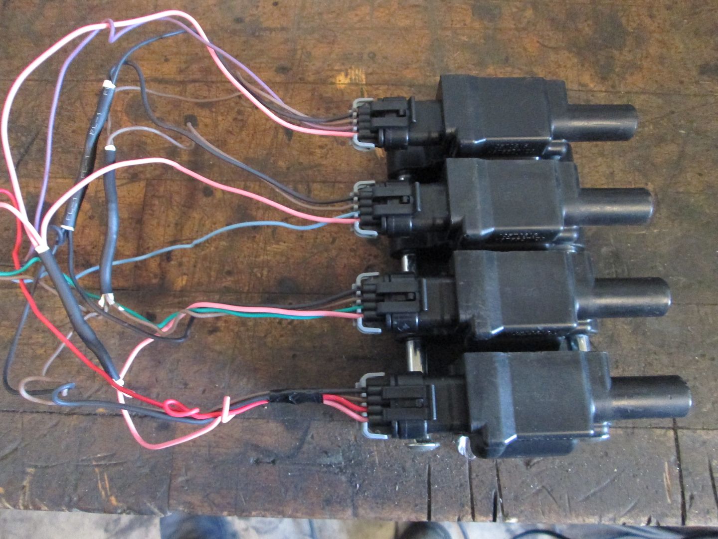
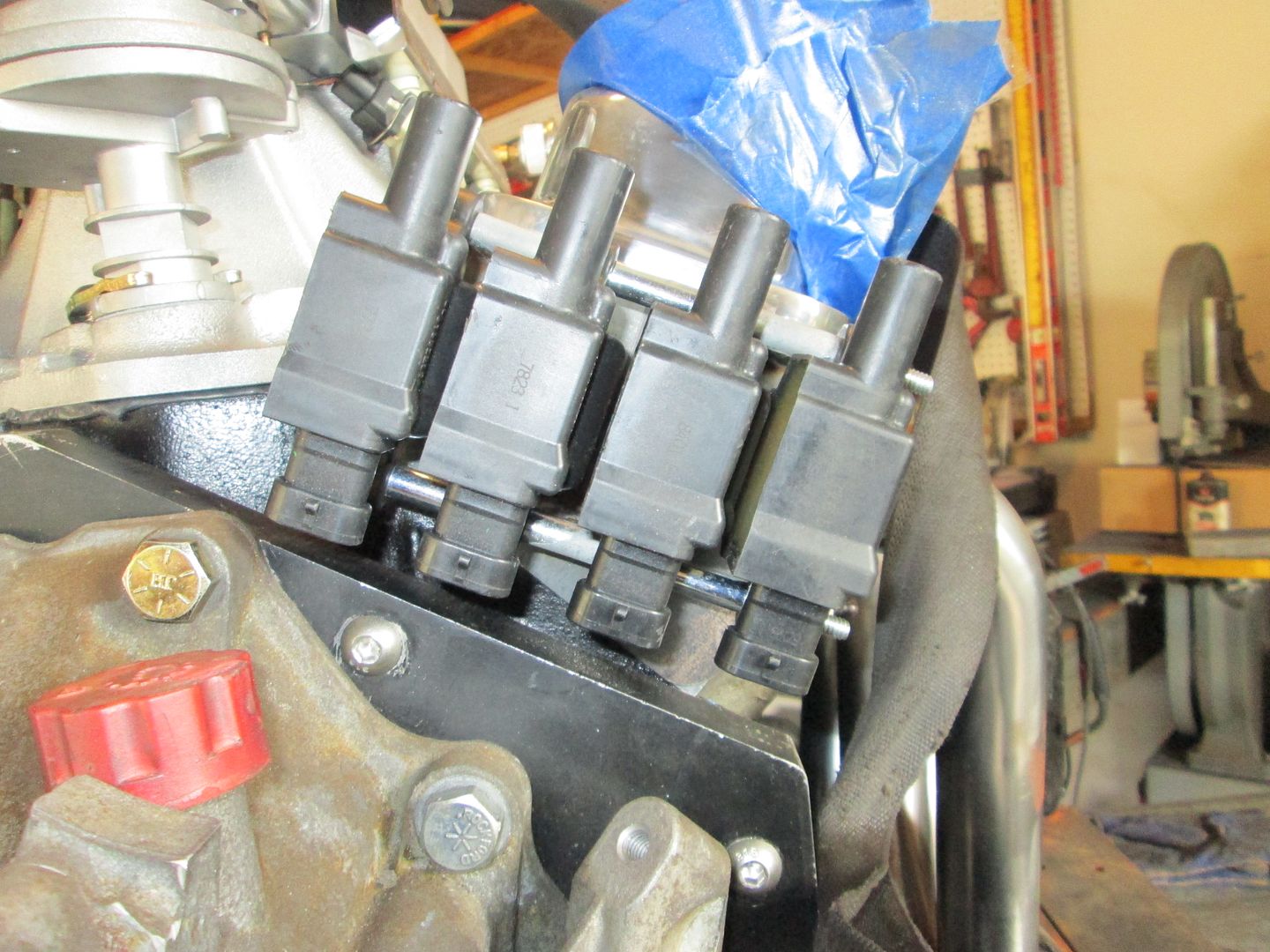
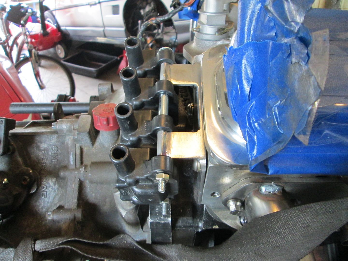
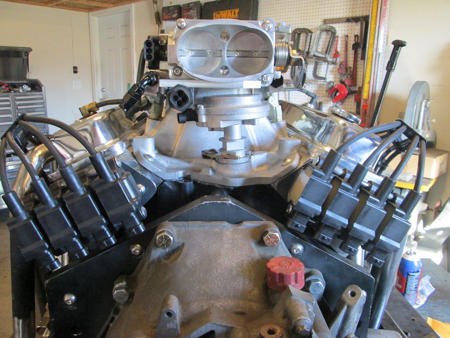
Then I got to work on the coils and mounting them off the heads. One of the big differences between the SBC and the LS4 is the distance from the head to bellhousing face as well as the adapter plate. I had to make sure that once the coils were mounted, the connectors could come off while clearing the adapter plate. To do a mockup with the wiring, I took one of the brand new coil sub harnesses and removed the plastic housing and all the tape:
Then using the same 1" spacers and a long 1/4" carriage bolt I attached the coils into a "pack" and connected the wires and did a test fit to determine how long the stand offs needed to be:
I laughed about your comment about whipping up some brackets, what came to mind was something like:
"No big deal, just cranked out a couple awesome adapters for the coil packs. Did some welding and cleanup work while sleeping, because damn I'm good."
Yeah, I though you would get a kick out of my word choice. Since there were essentially copies of the ones I made for the LS4, I knew what was needed.
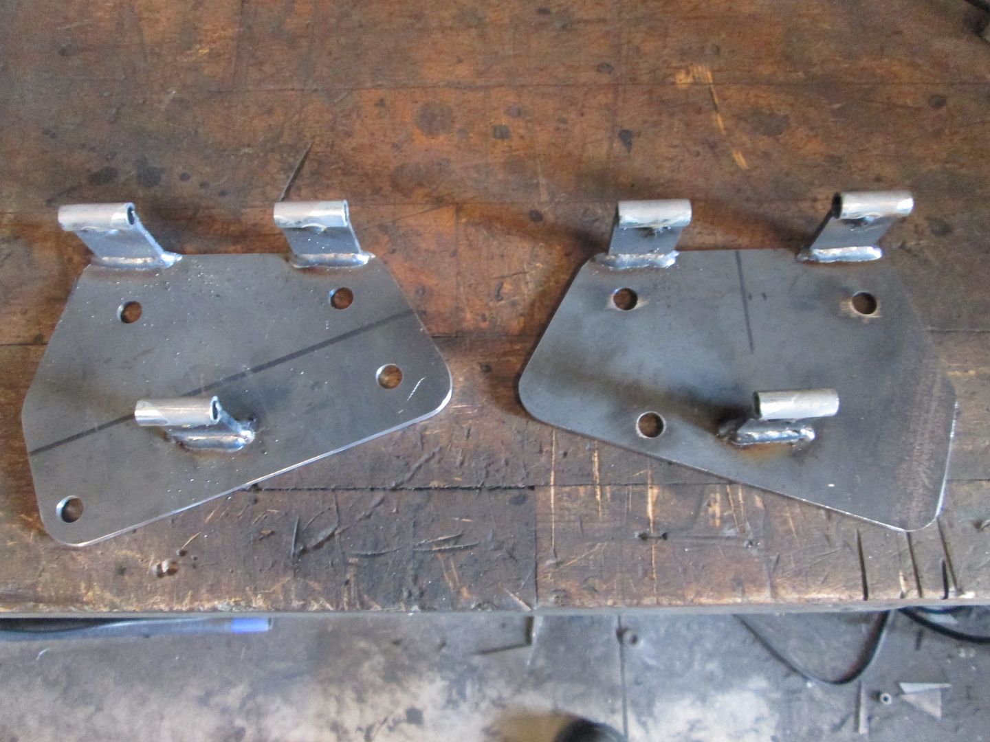
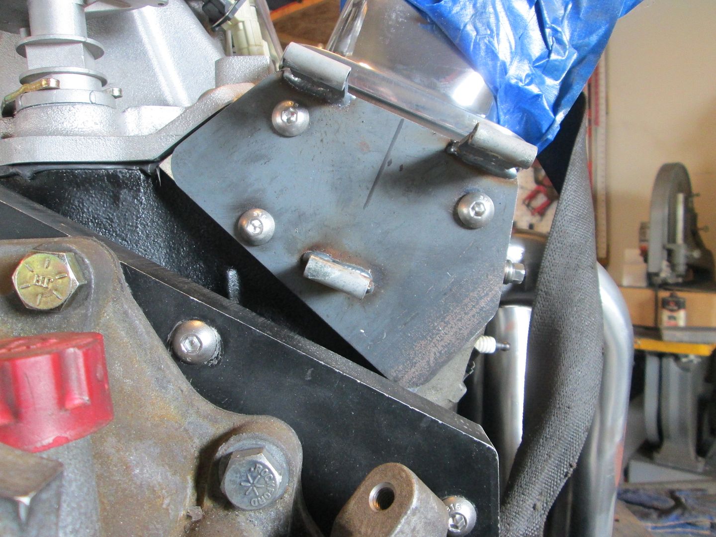
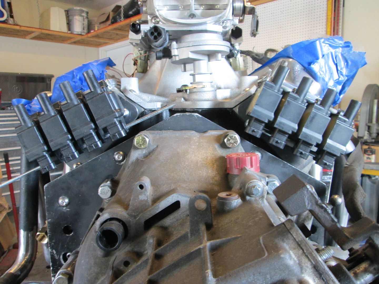
I thought I already had a template for the bolt patterns on both ends of the SBC heads, but couldn't find them, so used card board to trace the shape, transfer to 16ga and shear to size/shape. Refine the shape to match the head, then use the threaded center punches to transfer the bolt hole pattern one at a time. Once both 16ga templates were made, trace them on 1/8" plate, cut slightly oversize, clamp the template to the 1/8 plate while keeping a 3/8" gap between them, drill the bolt pattern, remove the spacers and bolt them together again, grind the 1/8" plate to the shape of the template, repeat for other bracket. Then back to the 1/8" plate and cut out six 1 x 1 1/4" rectangles, weld them to the 1" round sleeves, assemble the coil packs with the spacers and standoffs, position on the plate, tack weld the corners, disassemble everything, weld the standoffs, clean up the welds on the top side, round the corners, bolt to the engine, assemble the coil packs, take pictures.
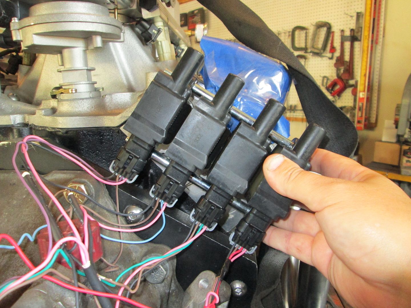
The only issue I came across with this set is if I used the single stand off on top and the dual standoffs on the bottom (like the LS4 ones), the bottom standoffs interfered with a bolt hole. So I flipped them and put the duals up top and the single on the bottom
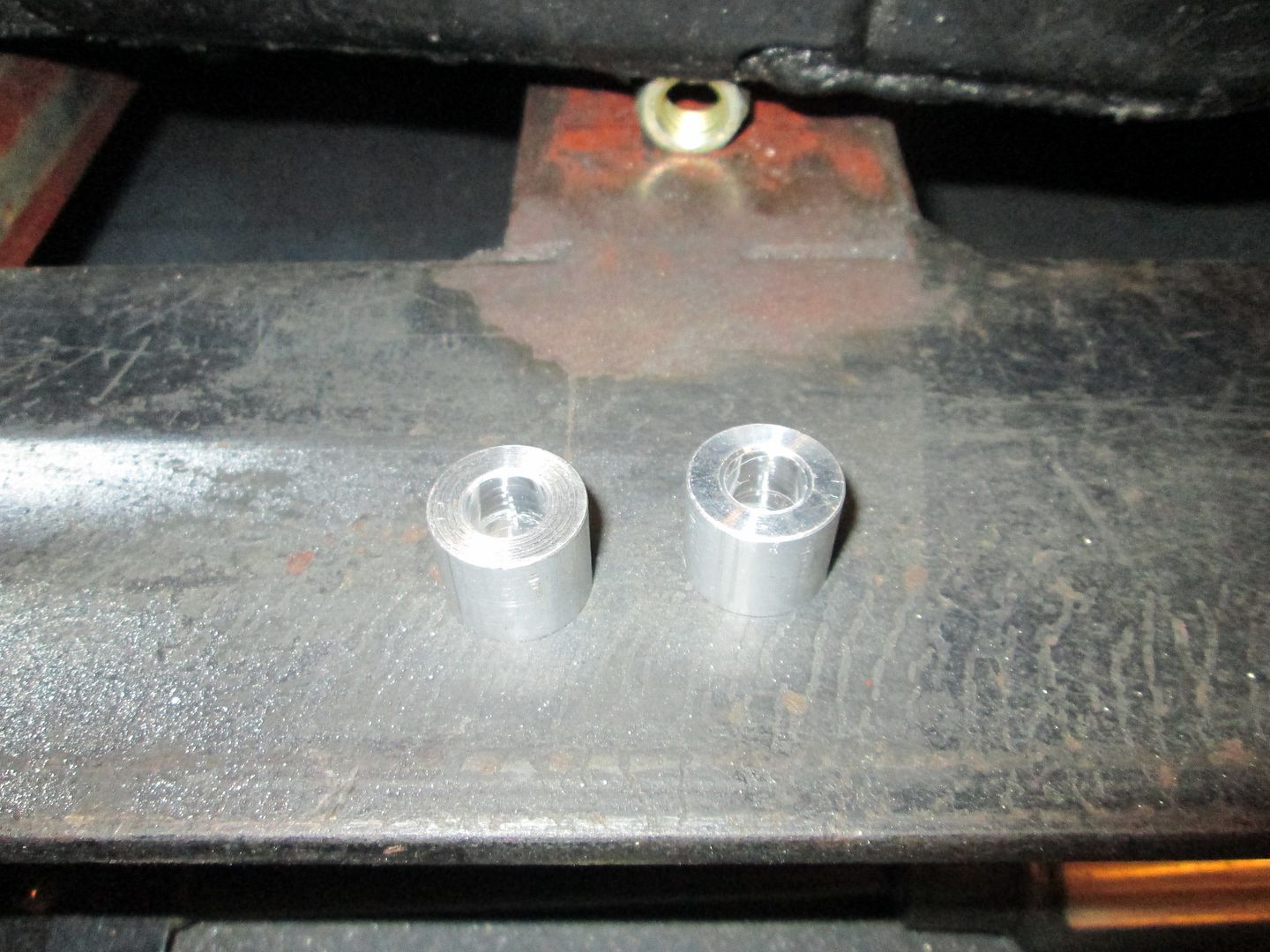
Started knocking out a lot of little things to finish the accessory drive. I turned some aluminum spacers to replace the washers used for mockup on the A/C bracket:
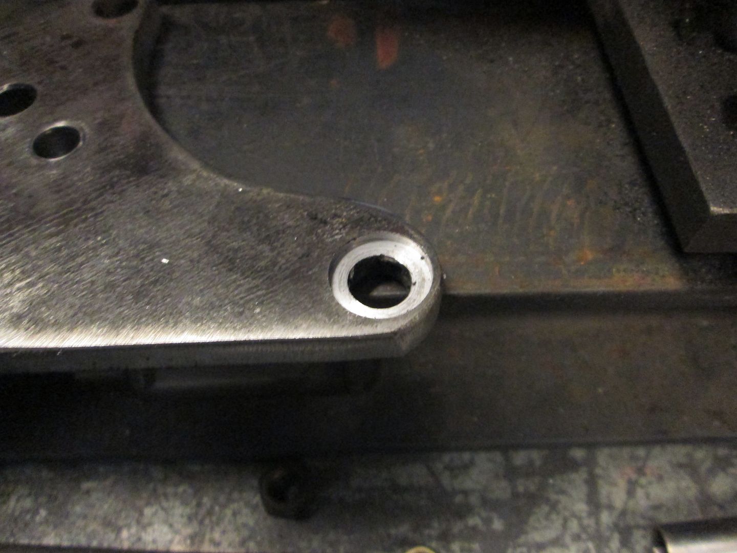
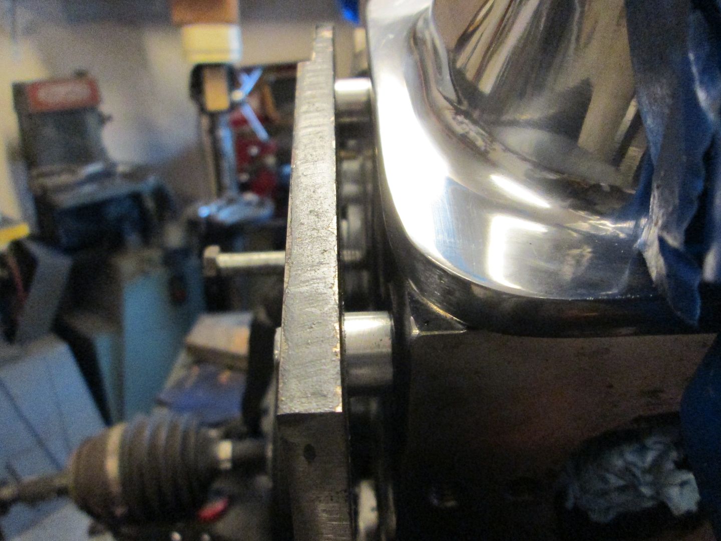
Also counter bored the bottom AC compressor hole so it will clear the belt:
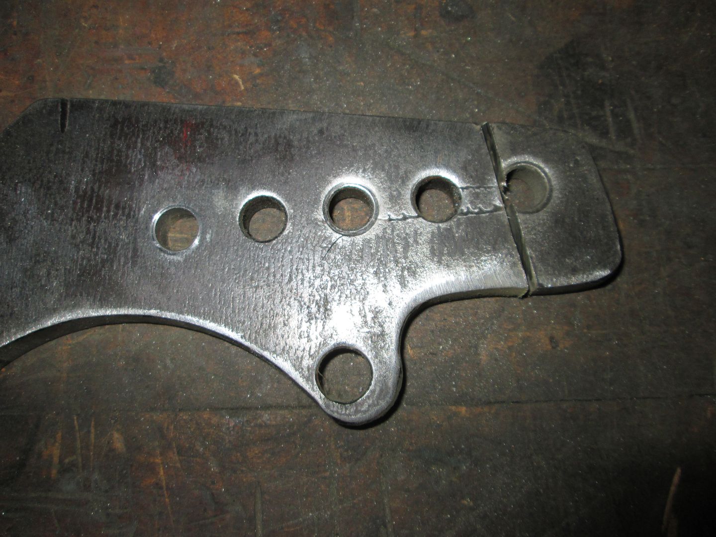
Trimmed off the top hole on the AC bracket so it would only have 4 holes like the engine bracket:
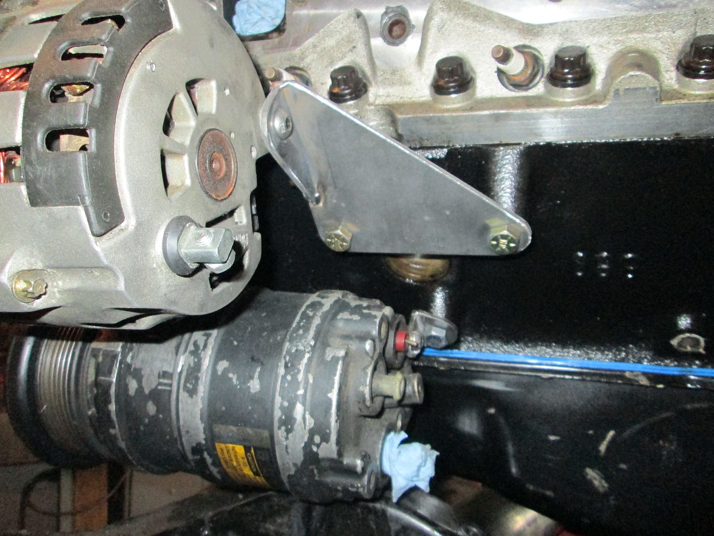
Then I fabbed up the rear support for the AC compressor:
Moving on to the Alternator bracket, I made some aluminum spacers to replace the washers:
Fabbed up the backside support bracket:
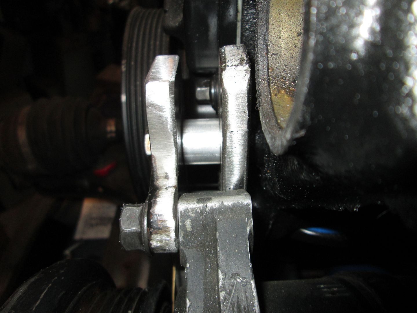
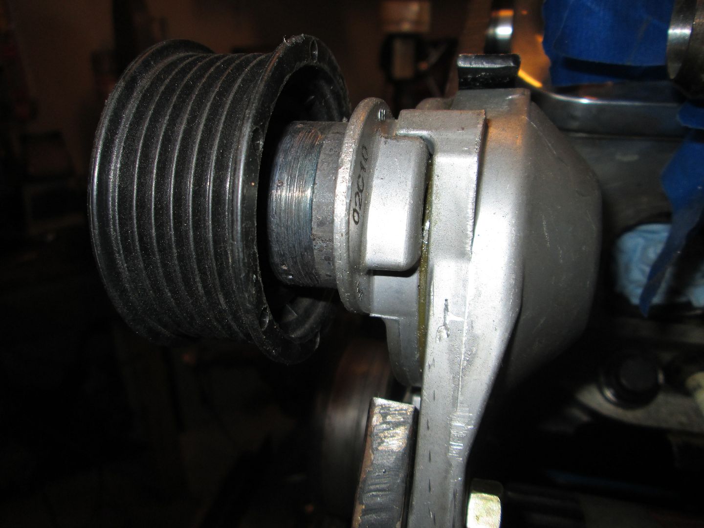
Fabbed up a spacer sleeve for the tensioner to properly align the pulley on the tensioner:
Found a spacer the right thickness for the idler pulley as well (I will pick up a new idler when I pick up the new belt):
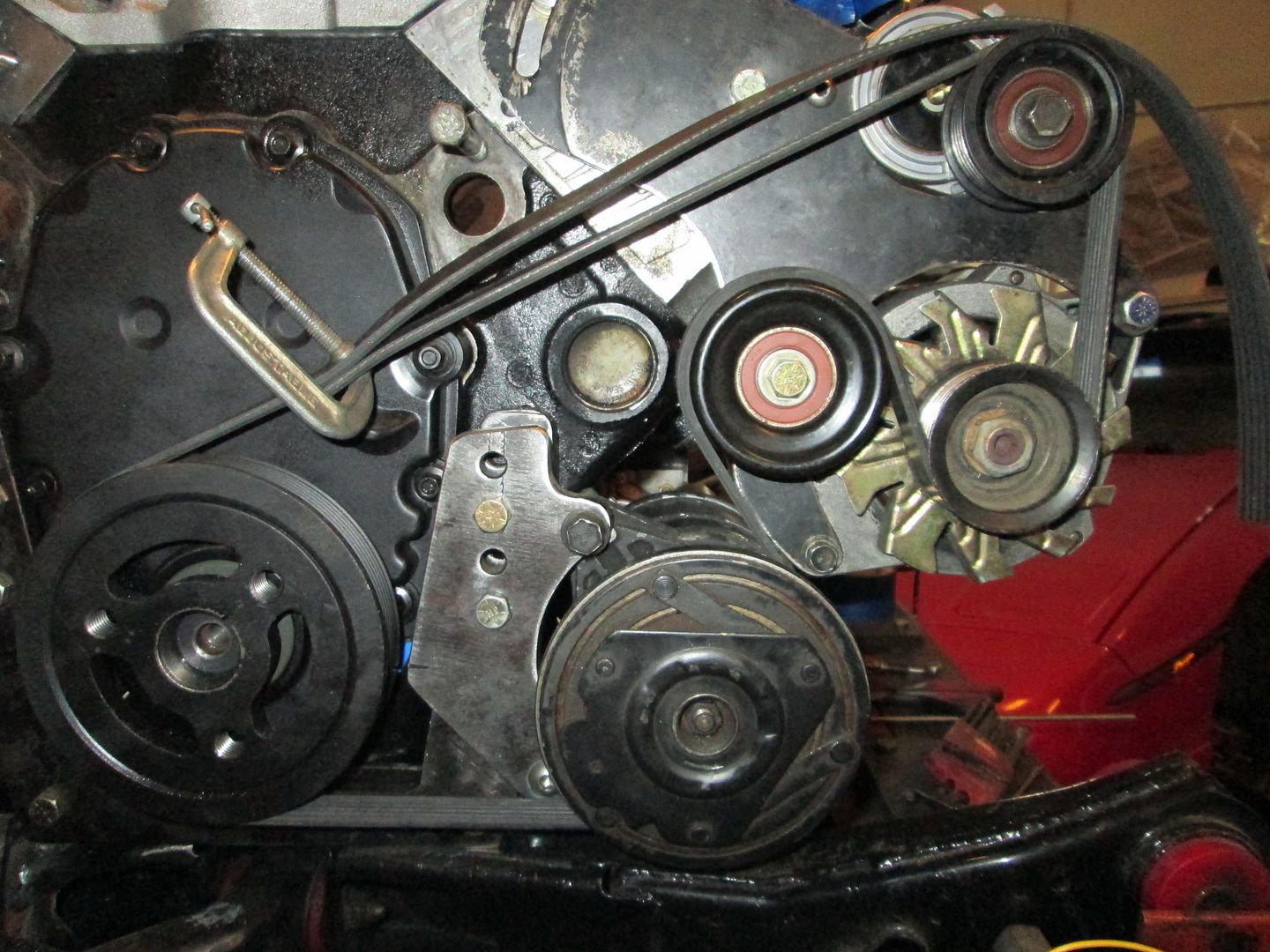
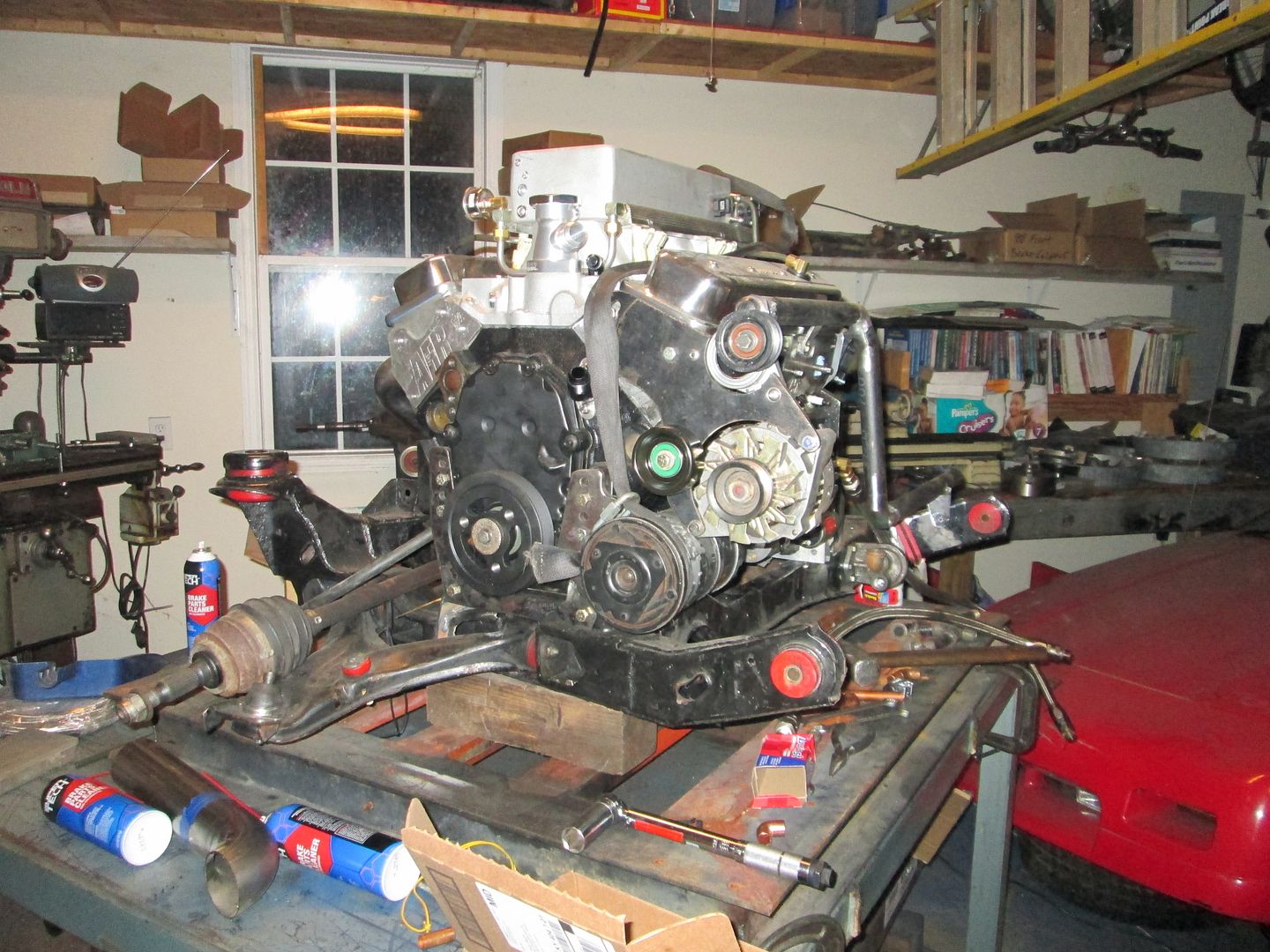
Mocked up the accessory drive to get the needed belt length:
[This message has been edited by fieroguru (edited 10-19-2013).]
Originally posted by joshua riedl: What cables does this transmission use?
This car was used for the Getrag F23 tutorial: https://www.fiero.nl/forum/Forum1/HTML/087296.html That thread states the car uses a stock Getrag Select cable and a custom length cable for the shift cable.
I am a stickler for detail and think the statement that it uses a stock Getrag select cable is somewhat misleading. The only reason the select cable works in this Fiero is because it is of the adjustable aftermarket style. The stock OEM getrag select cable as well as the cables from Rodney Dickman are non-adjustable and will not work with this bracket setup.
Here is a picture of a Rodney Dickman Getrag Select cable (top cable) side by side the one that is in this car. Notice in the fully retracted state, the distance from the mounting boss and the ball ends are significantly different, and you can see quite a bit of the adjustment has been used to make the sleeve of the cable longer. https://www.fiero.nl/forum/Forum1/HTML/087296.html
I would classify this as a modified sleeve length getrag select cable.
I already have my car setup with stock select cables and saw you broke yours and was wondering if this car had a stronger solution. It shifts nice but I'm afraid to jam the gears. I also noticed that even with my adjustable pushrod as short as it goes I'm having an over travel issue where the clutch reengages. I'm wondering if this is a spec clutch issue or an f23 issue. Easy fix either way I suppose. Great build though, it one of the few threads I look forward to when I see updates.
I already have my car setup with stock select cables and saw you broke yours and was wondering if this car had a stronger solution. It shifts nice but I'm afraid to jam the gears. I also noticed that even with my adjustable pushrod as short as it goes I'm having an over travel issue where the clutch reengages. I'm wondering if this is a spec clutch issue or an f23 issue. Easy fix either way I suppose. Great build though, it one of the few threads I look forward to when I see updates.
The cable issue on my F40 swap is due to using the thinner select cable for the shift cable. The forces the shift cable sees are just too high for the select cable. This F23 swap has a legitimate shift cable for the shift functions, so it should be OK.
The overextension issue is likely a mismatch between the HTOB travel, the design of the pressure place fingers, and the clutch disk or a combination there of.
Knocking out several little odds and ends as I get ready for another test fit.
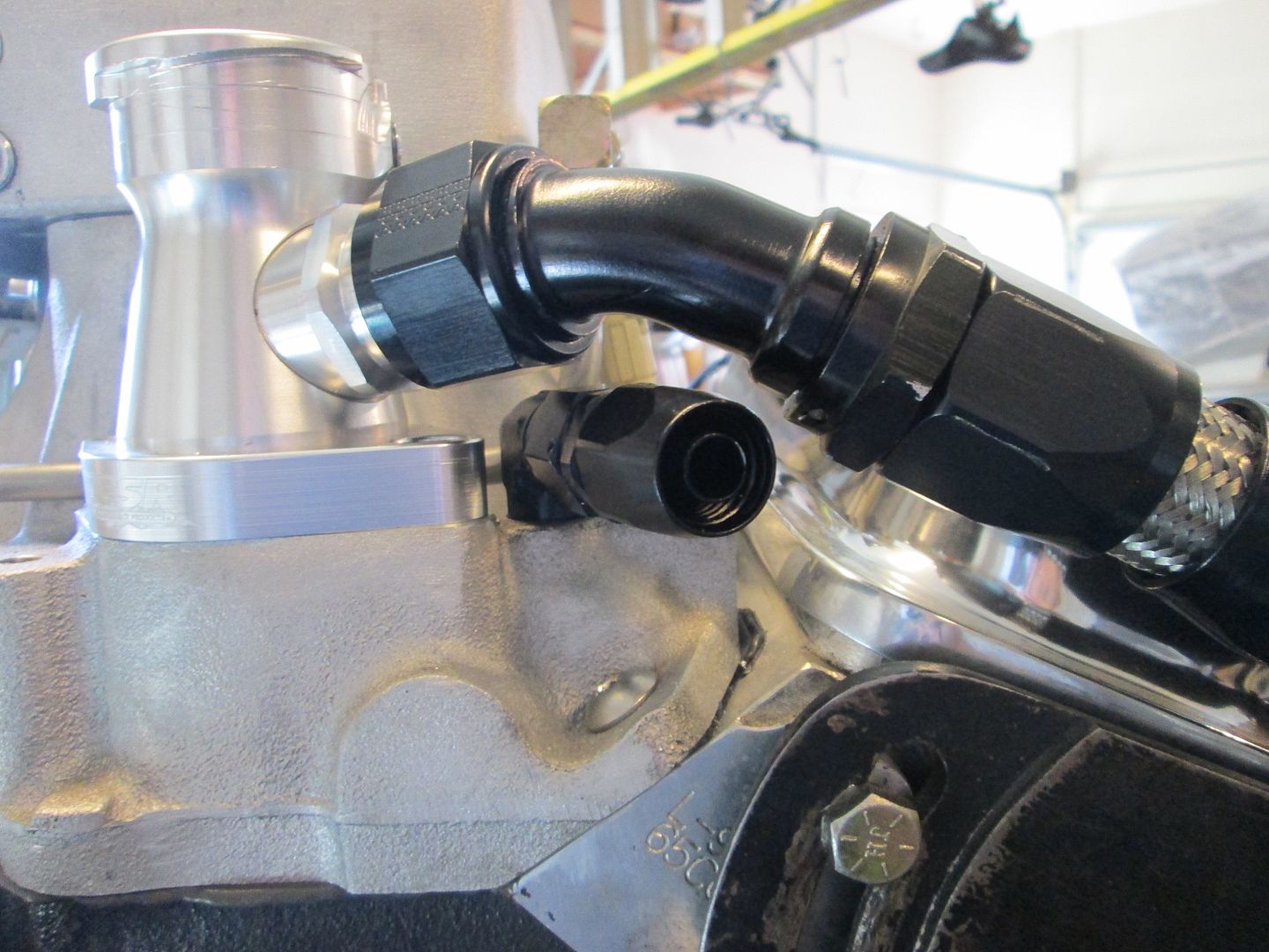
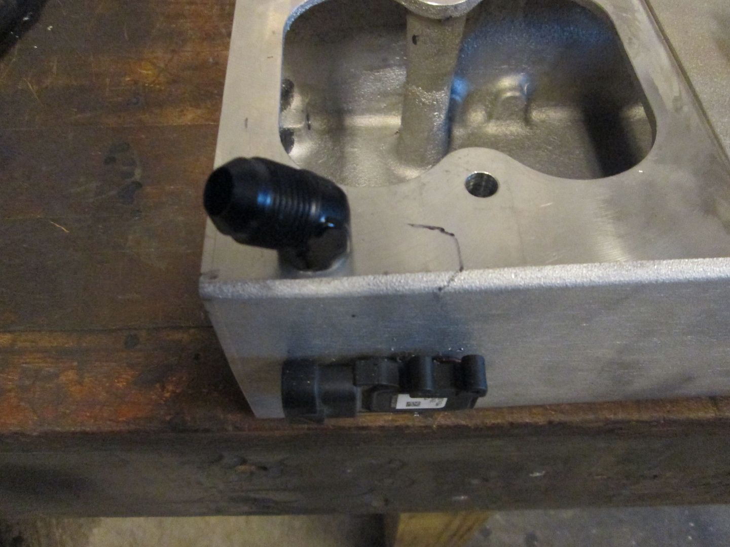
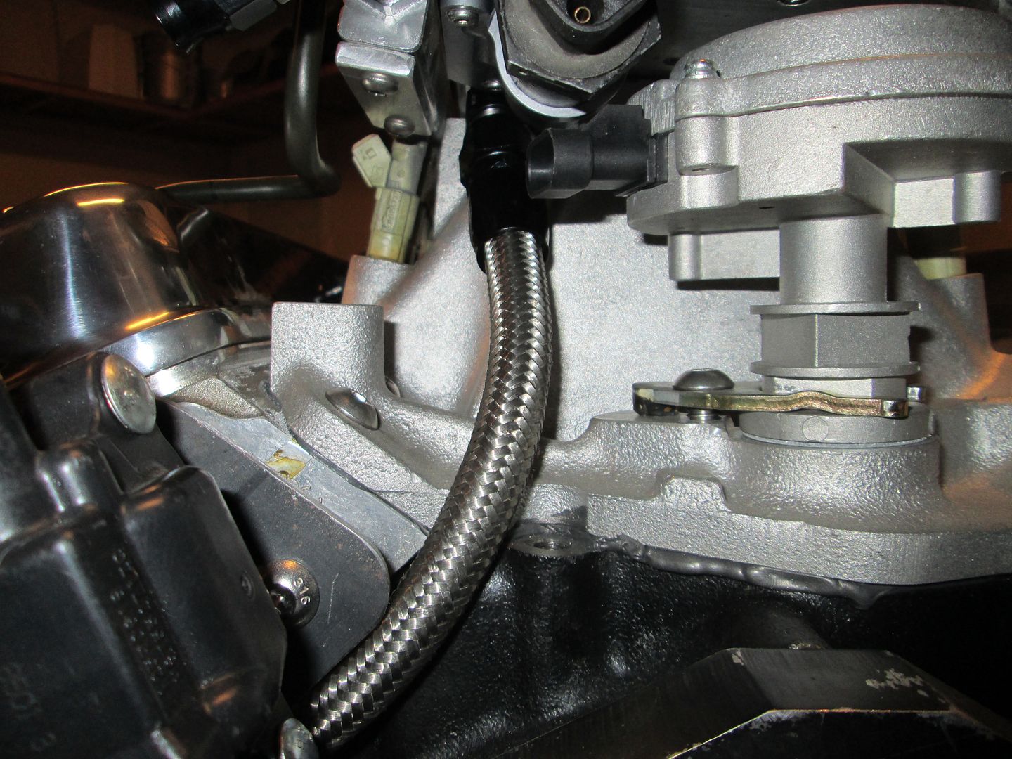
Installed the heater supply AN fitting and hose end:
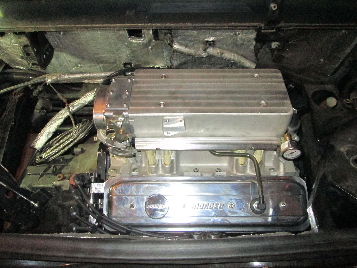
Installed the AN fittings for the water pump as well and took a picture of the accessory side nearly done (except belt and paint):
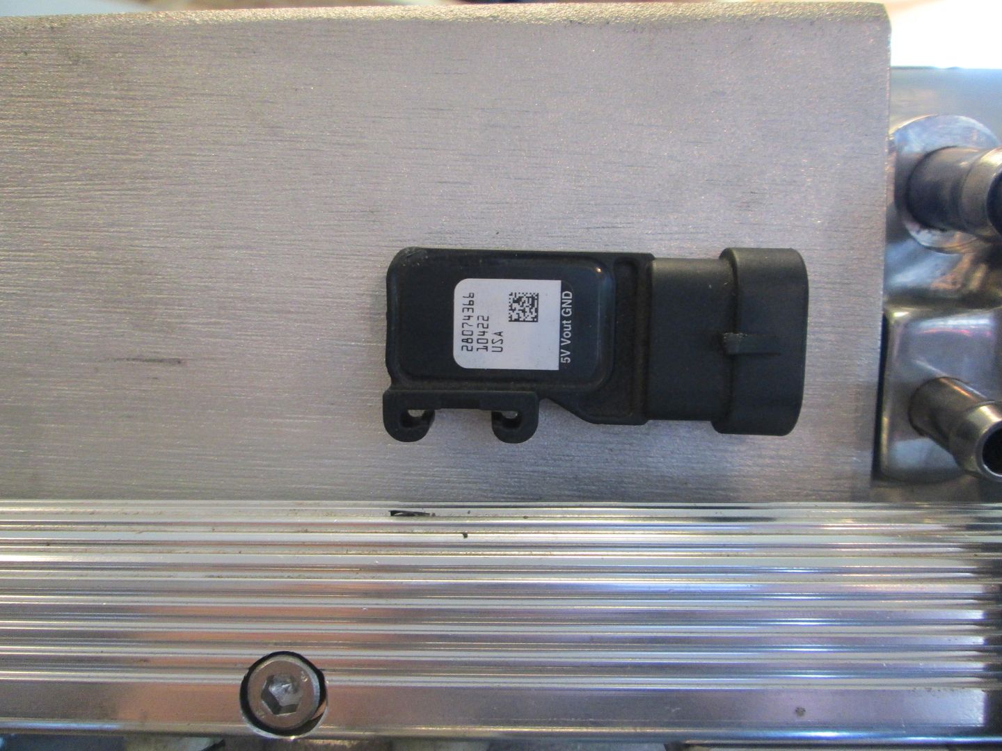
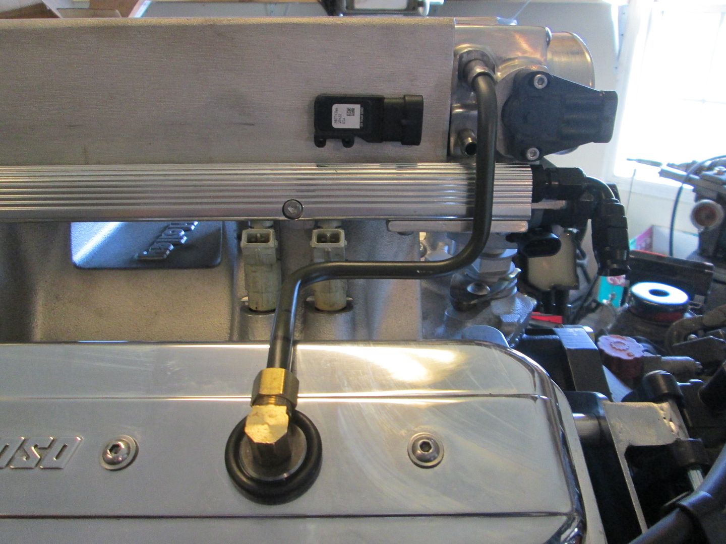
Installed the MAP sensor to the upper plenum. It is on the front side of the plenum, so you won't see it, but it still is easy to get to for future replacement:
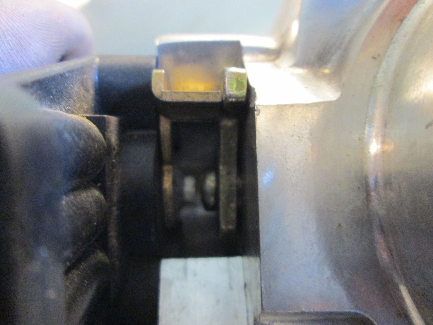
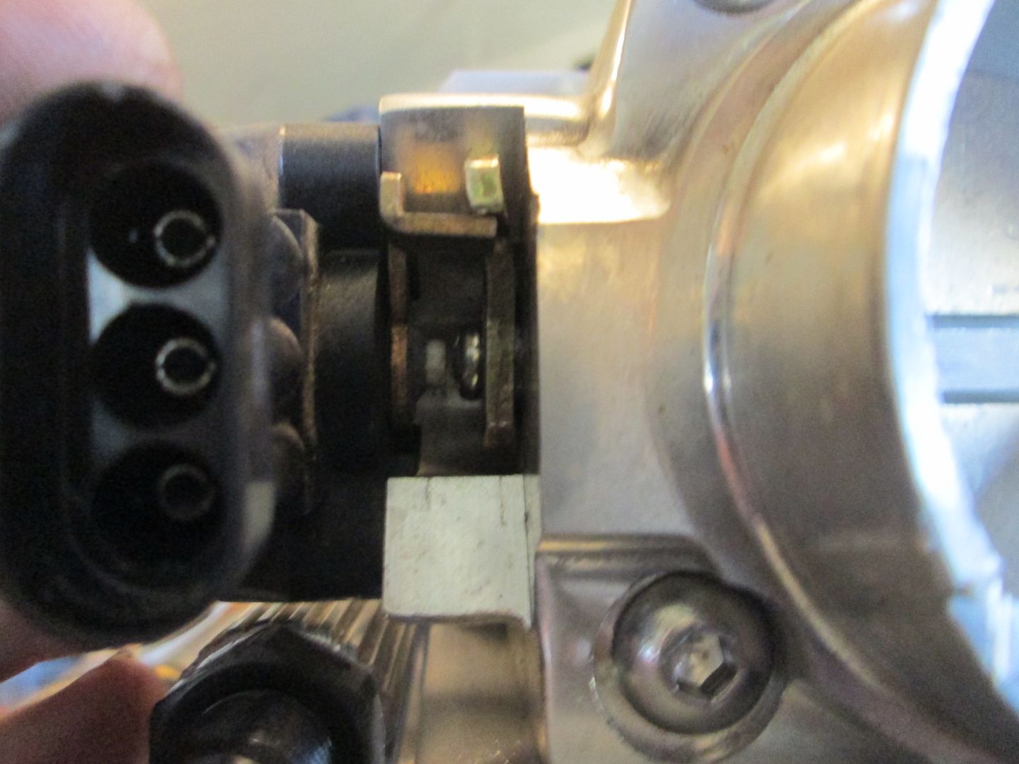
Tweaked the throttle body TPS lever so it would engage the sensor lever. Here is a before pic:
After:
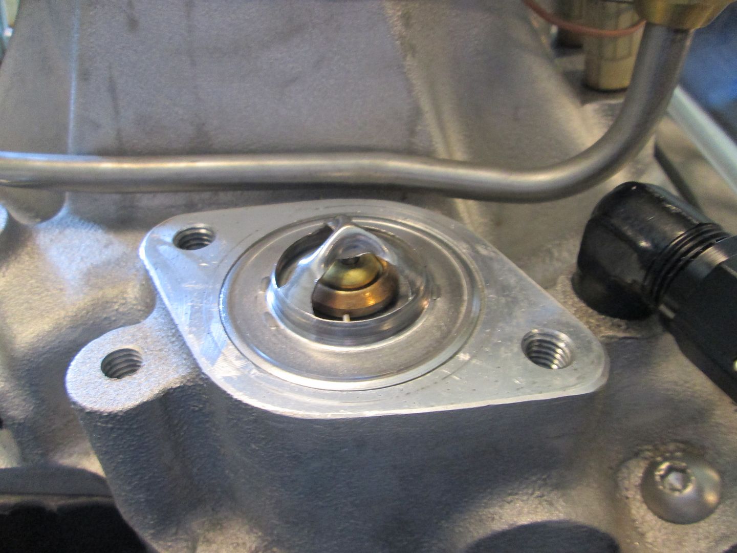
Installed a 180 degree thermostat:
Plugged the vent line hole in the thermostat housing:
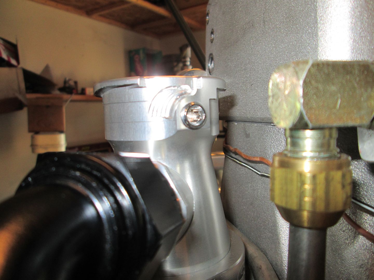
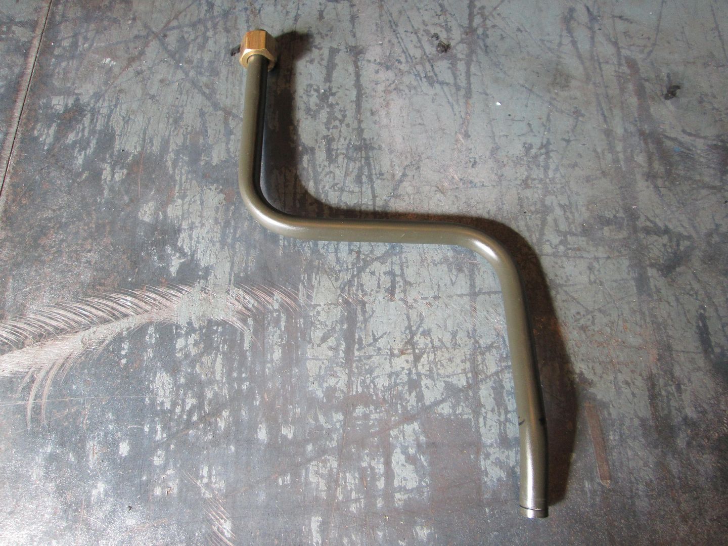
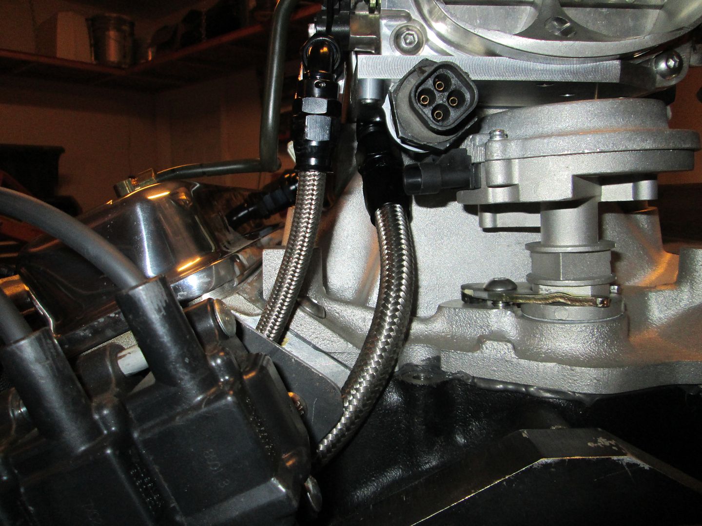
Thought about the PCV routing and ended up flipping the valve covers side to side so the PCV can be on the rear one (along with the oil fill) and the front one is for the clean/metered air inlet. The rear side I used a brass compression fitting on the underside of the intake and then bent up a hard line that connects to the PCV valve with some head shrink (not shown). The front side I made a housing for another compression fitting, then bent up a hard line to the throttle body where more heat shrink will be used to seal the throttle body end. These hard lines will be painted black before final assembly.
Here is the rear PCV line:
Here is the front PCV line:
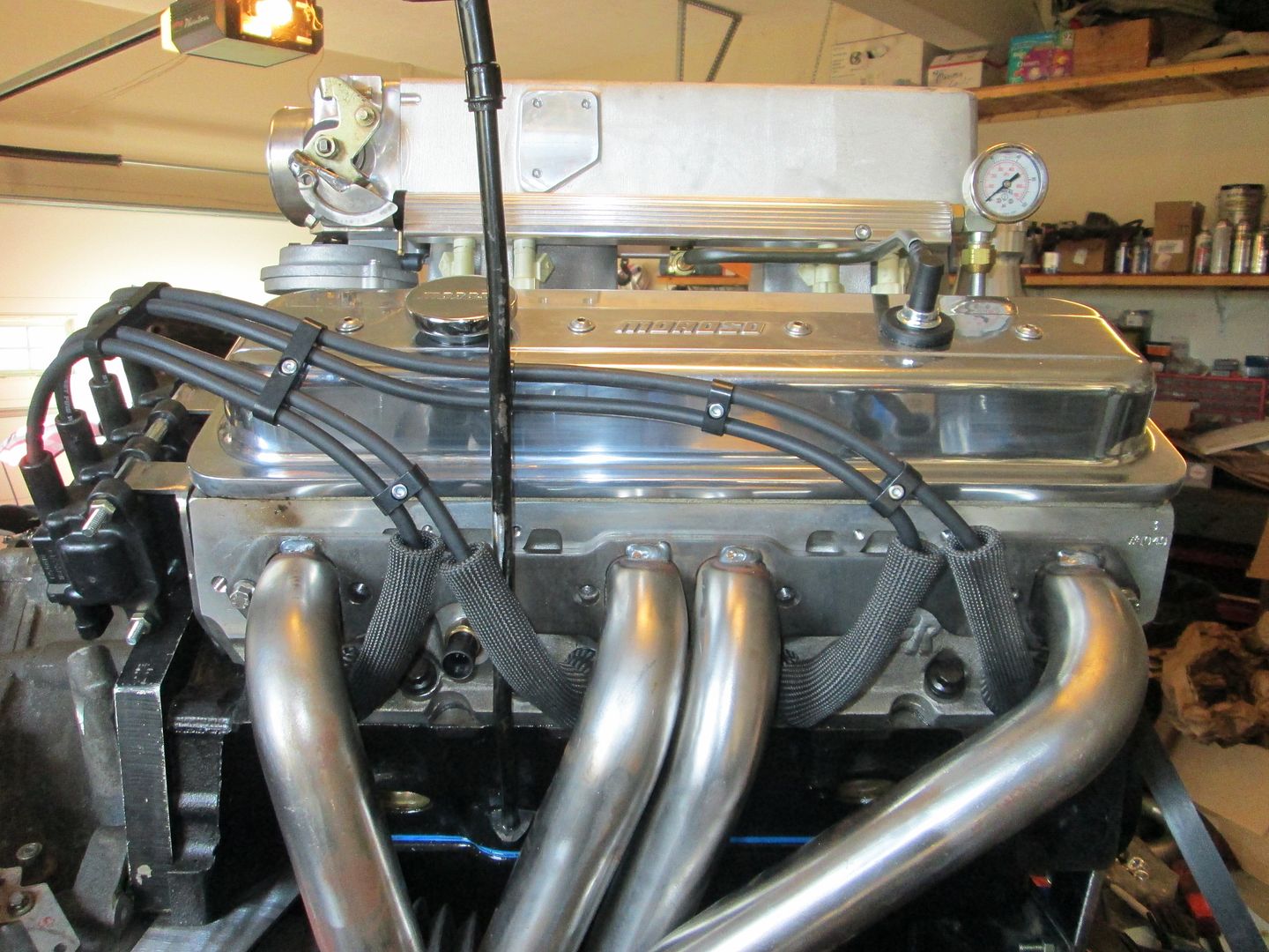
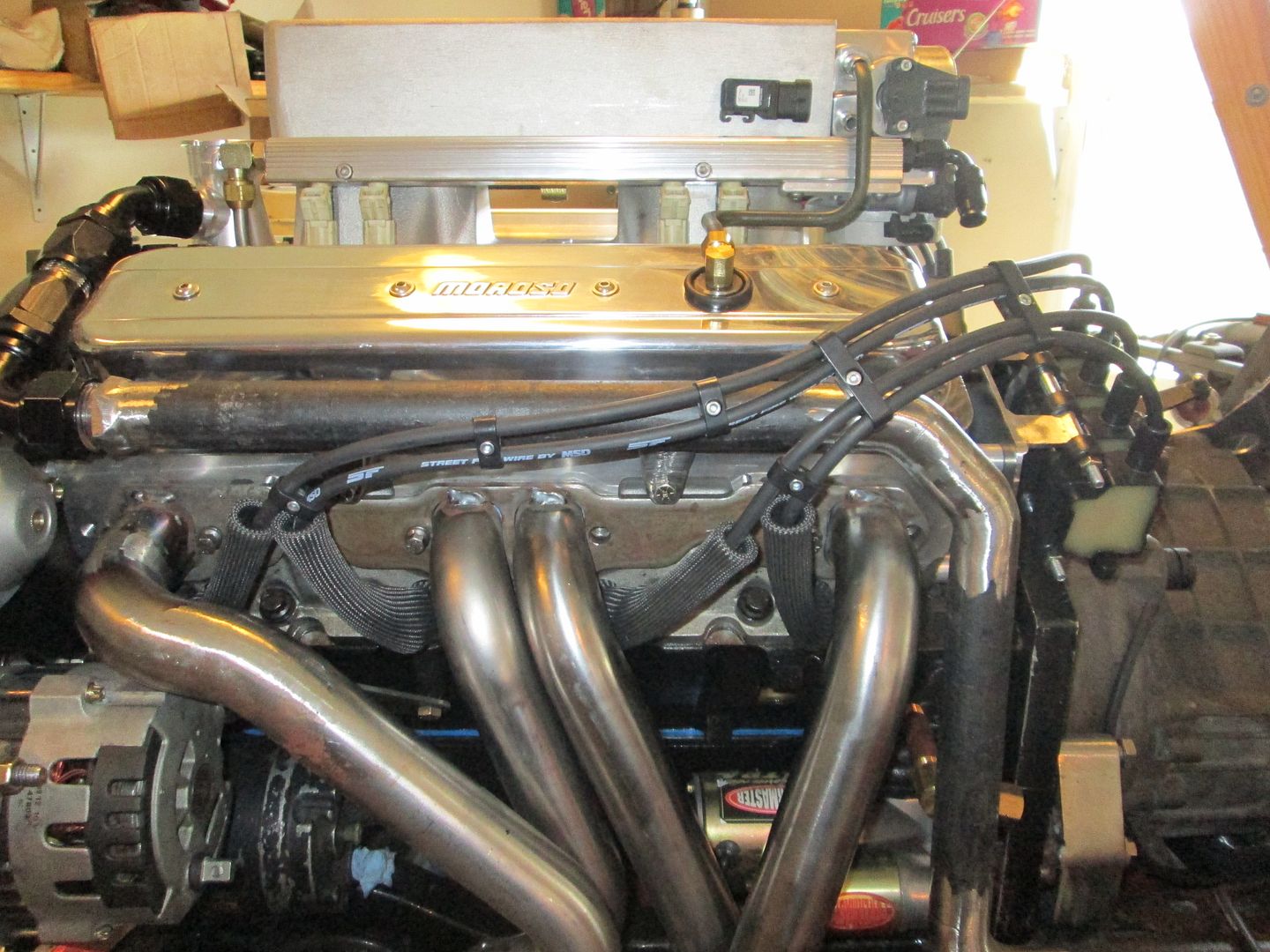
Started routing the plug wires. Every plug end has a DEI boot protector sleeve to keep header temps from causing damage. The coils boots are not installed as I like to mock the wires up and take some time to look at them before locking into the final routing. But I think this routing has promise.
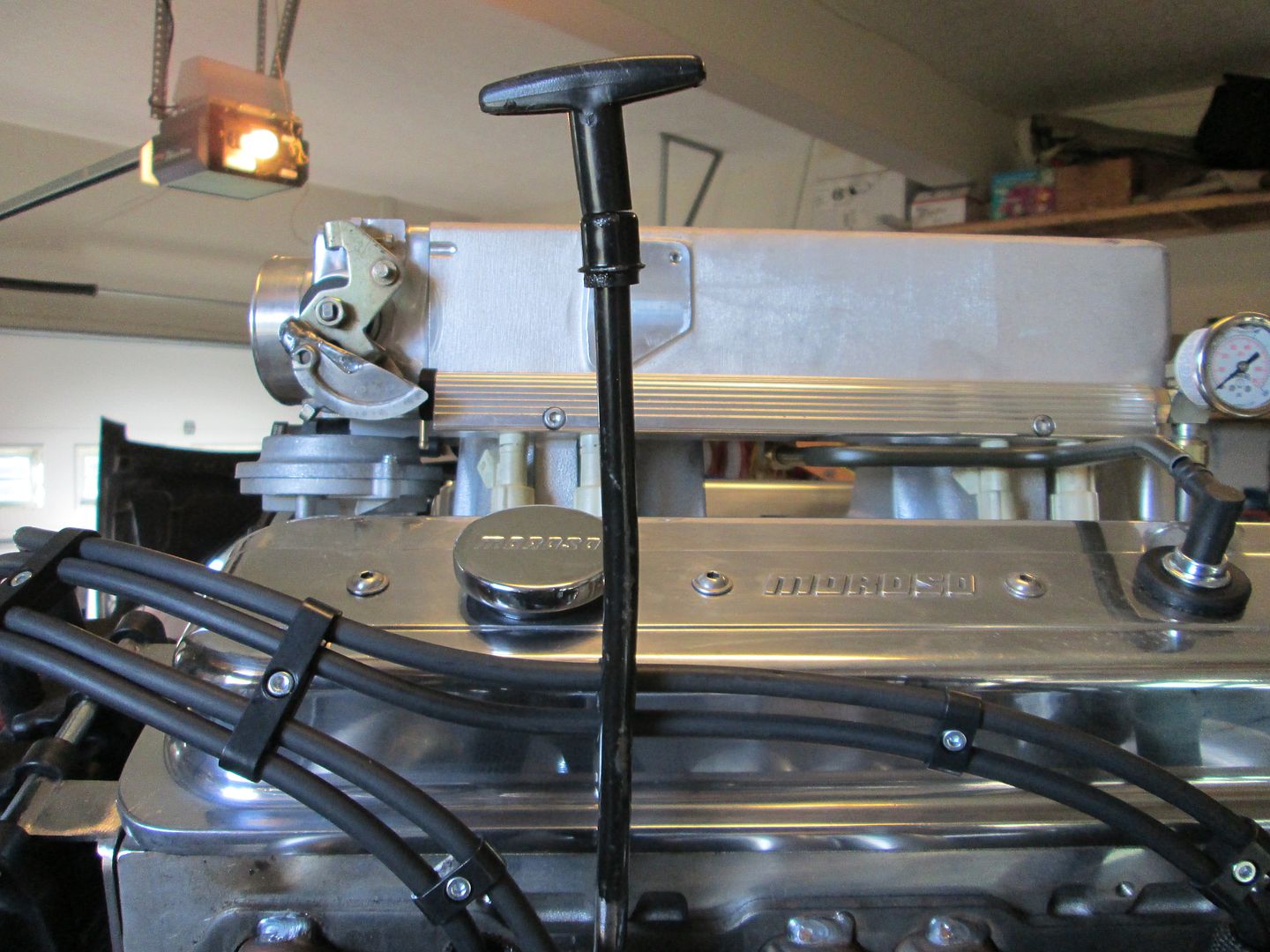
I straightened the oil dipstick, removed the mangled bracket, and then reshaped it for a decent route past everything. I still need to cut it down (way too tall) and make a new hold down bracket.
I am hoping to do another test fit some time this week to verify the shifter bracket, work on water pump placement and hose routing, fab up the throttle cable bracket, fab up the cold air intake, and do some pondering on the exhaust.
[This message has been edited by fieroguru (edited 10-20-2013).]
It looks awesome but I have to laugh. I keep seeing pics of this wonderful beast of an engine and there, tucked away under it is the same tired ol' crummy a/c compressor without so much as a lick of paint to make it look 'nice'. Truly fabulous work though.
------------------ Anything I might say is probably worth what you paid for it, so treat it accordingly!
When it comes to the A/C... as long as it's functional I'm happy. Besides, buried down there, it'd get so dirty and such, I don't worry about it. I don't even know if there are better (or smaller) compressors out there, or if it'd be worth it to slap a smaller one in there.
Originally posted by ltlfrari: It looks awesome but I have to laugh. I keep seeing pics of this wonderful beast of an engine and there, tucked away under it is the same tired ol' crummy a/c compressor without so much as a lick of paint to make it look 'nice'.
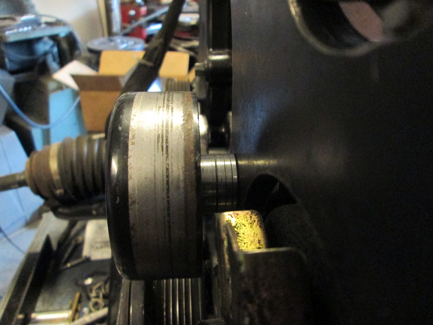
I did scrape/knock about 1/4" of grease/grime off the compressor, does that count? However, the picture of the end does show that the compressor is still in need of some cleaning.
This is just the mockup stage. Once everything has been fabricated/test fitted, then it all comes apart for further cleaning/painting. However, painting the A/C compressor wasn't in the scope of work, and I hadn't plan on doing much more to it than brush it off.
quote
Originally posted by ltlfrari: Truly fabulous work though.
Thanks!
[This message has been edited by fieroguru (edited 10-20-2013).]
Trimmed down the oil dipstick tube. Now I just need to remove the roll pin that secured the top, drill a new hole in the dipstick metal, then cut the excess off, then reassemble.
Put the drivetrain back into the chassis for hopefully the last test fit. I plan to connect all the hoses, cables, air intake, water pump and thottle before pulling it back out again for cleaning/painting and the engine bay detailing.
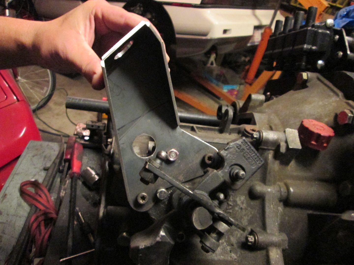
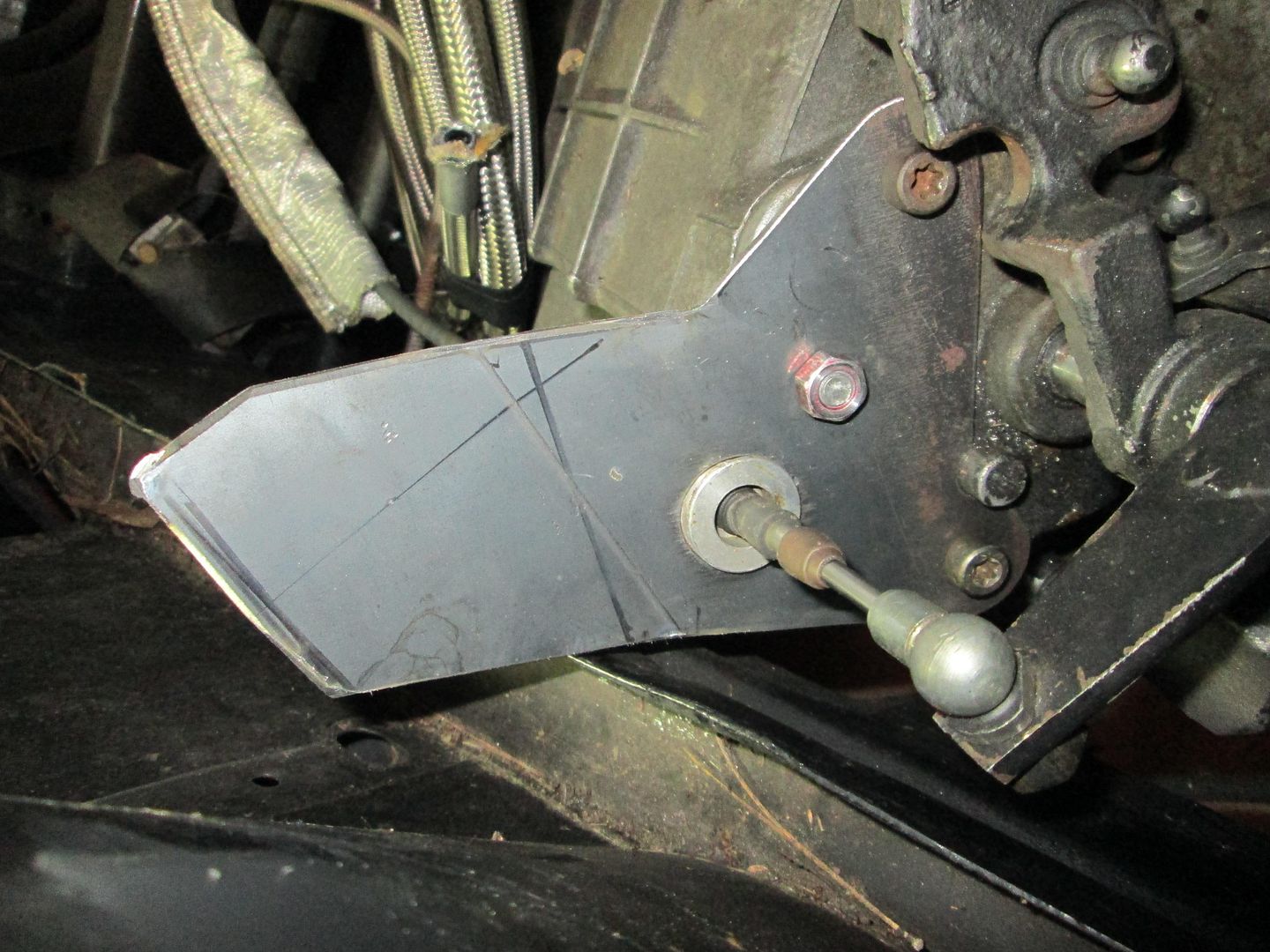
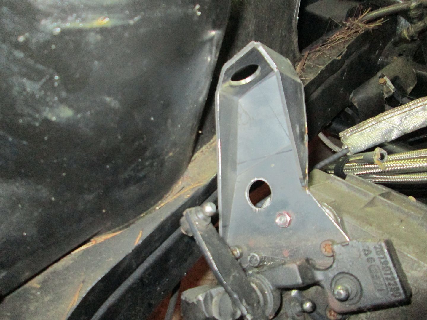
The first minor issue the test fit revealed was I needed to tweak the shape of the shifter bracket. Since it didn't fit as tacked together, I cut the spot welds and tested the base place and it fit just fine:
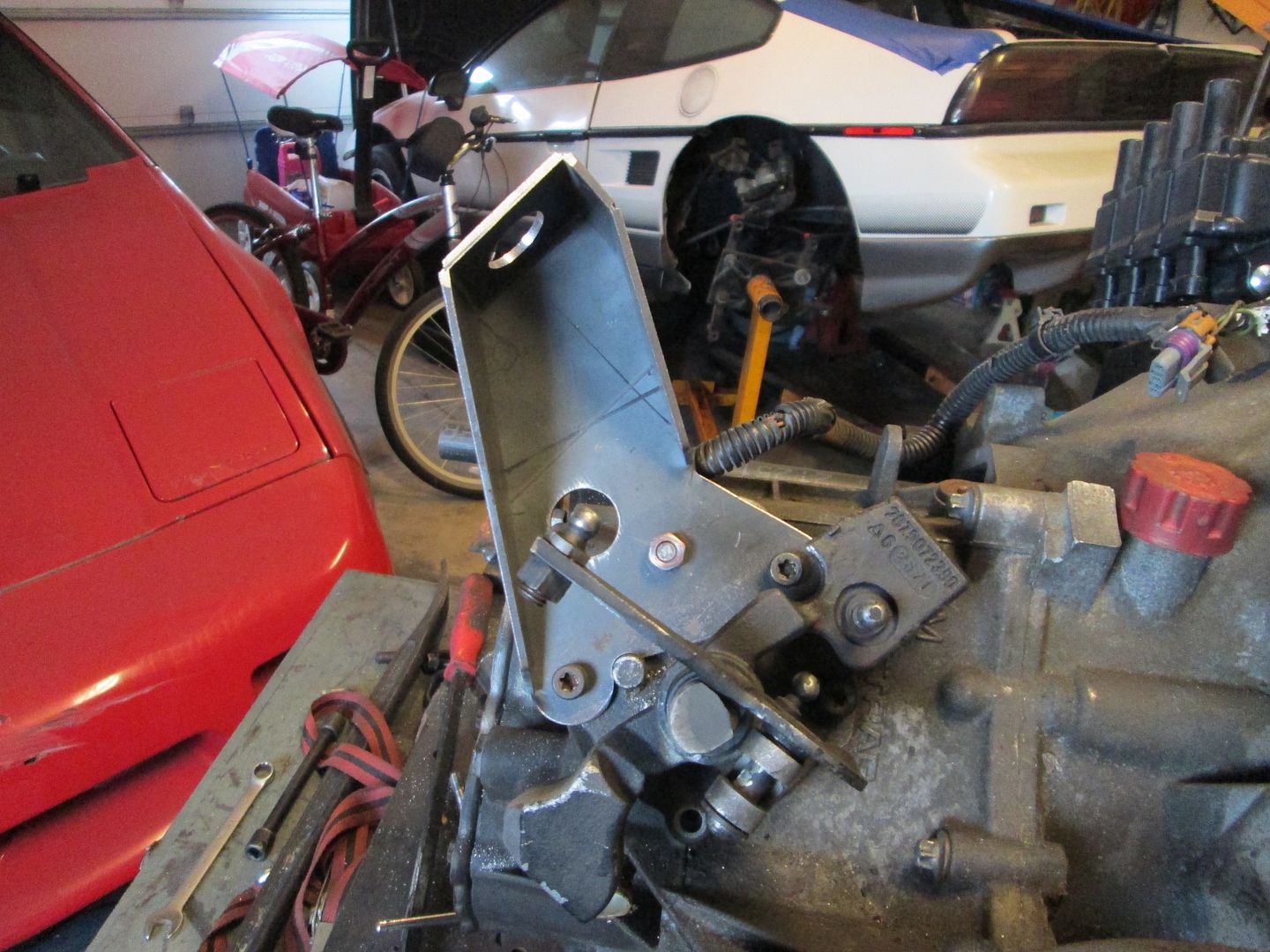
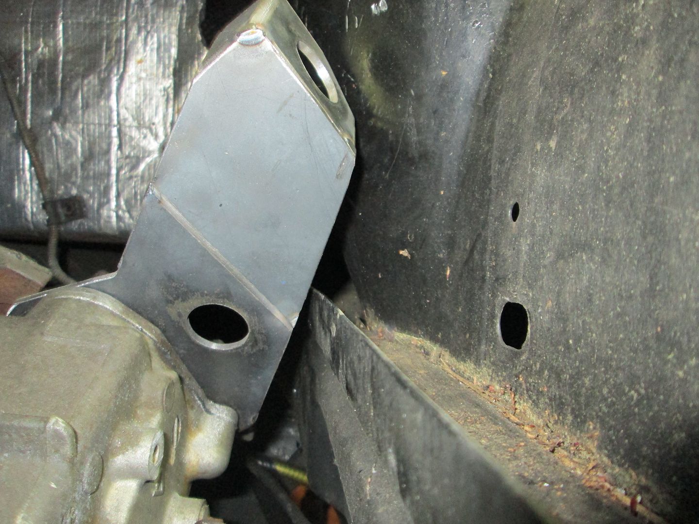
Then I slid the top part of the bracket as close to the strut tower and marked where it needed to be trimmed:
Trimmed, smoothed, tacked and ready to go back in:
The coolant fittings for the water pump fit like they should:
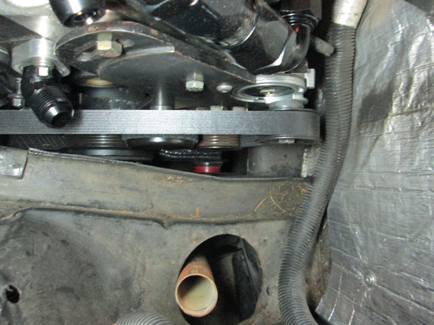
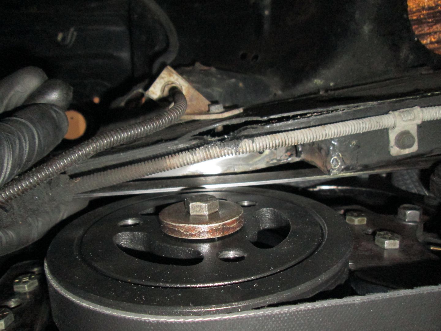
The heater hose will go down in the small space between the belt and the passenger frame rail. It will be clamped to the passenger frame rail to keep it away from the belt:
The rear header clears everything in the rear and the front one has even more room:
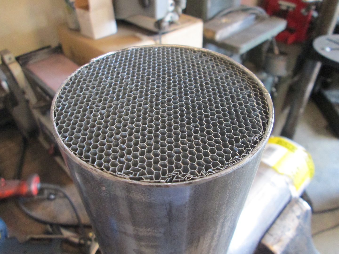
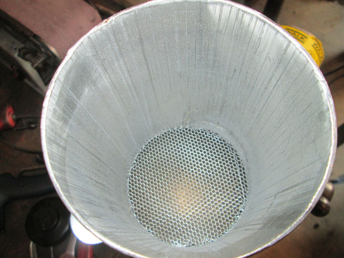
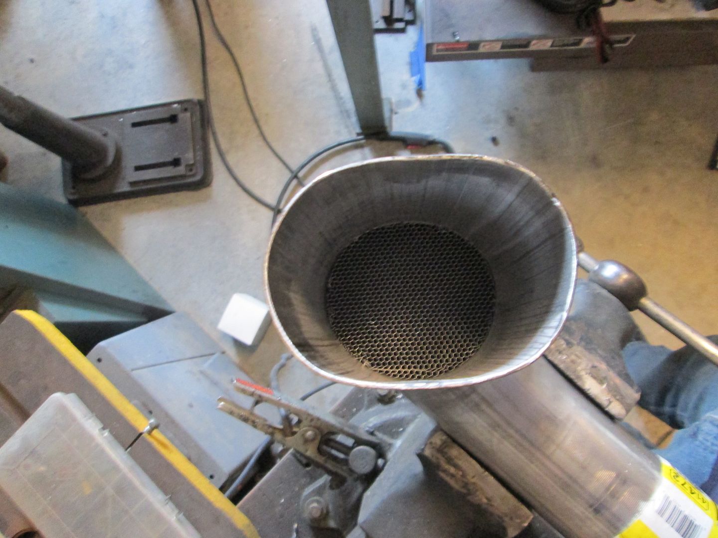
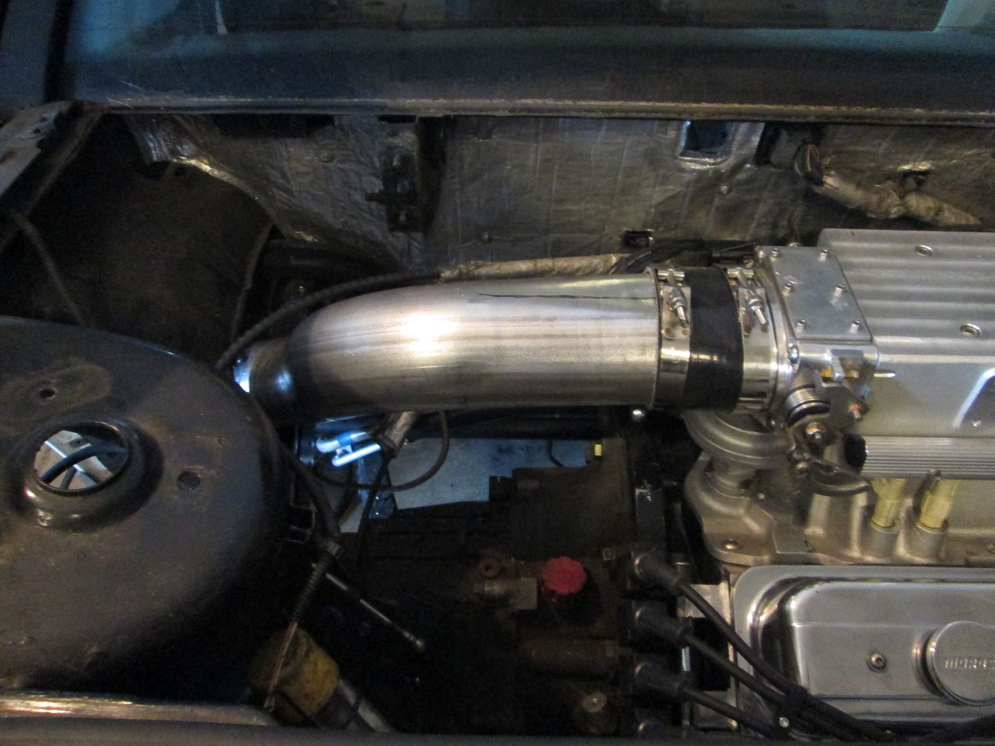
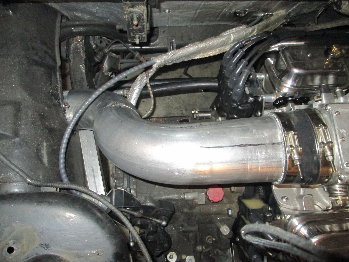
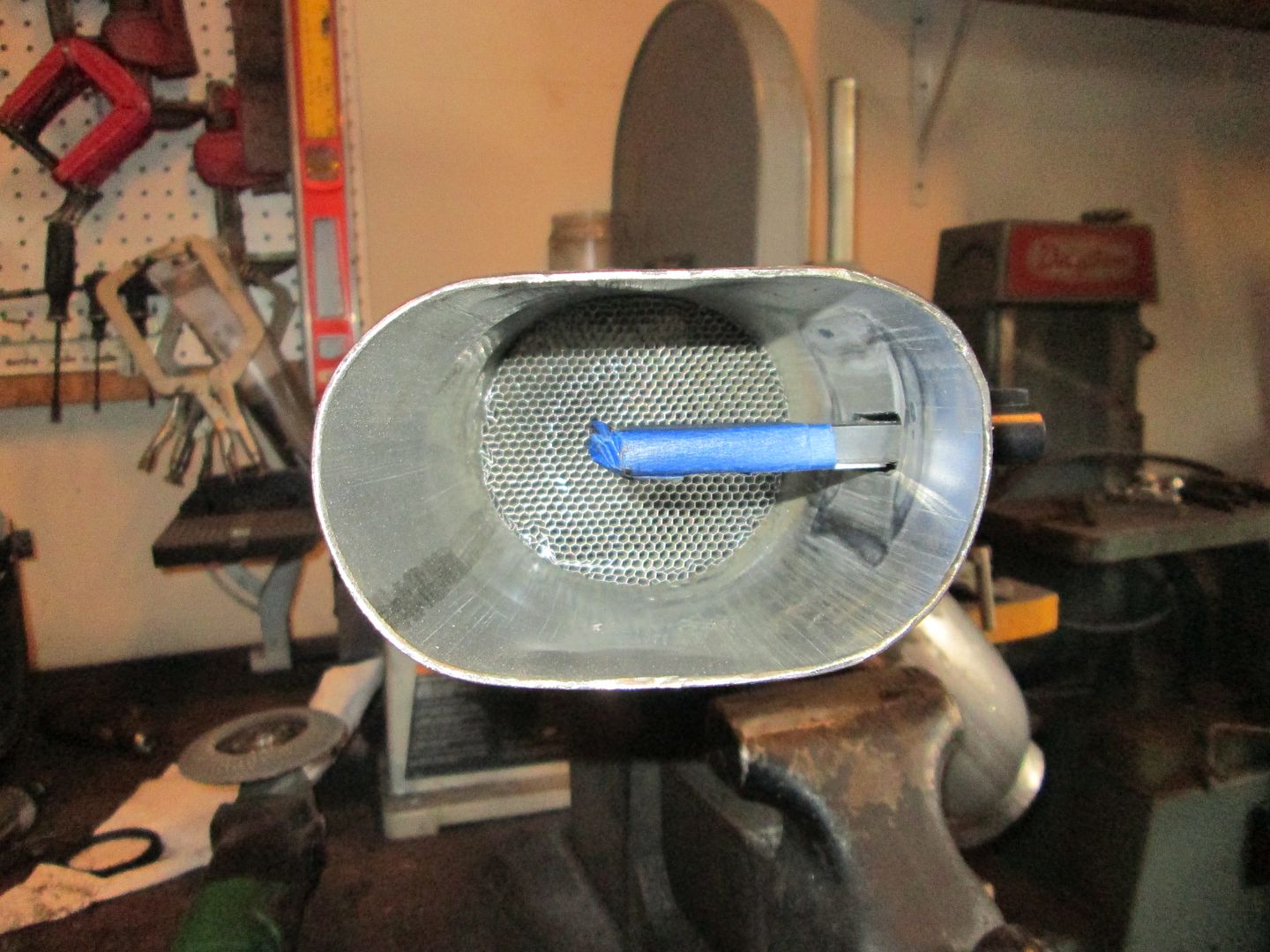
Step 1 was press in the honeycomb mesh for the LS7 MAF:
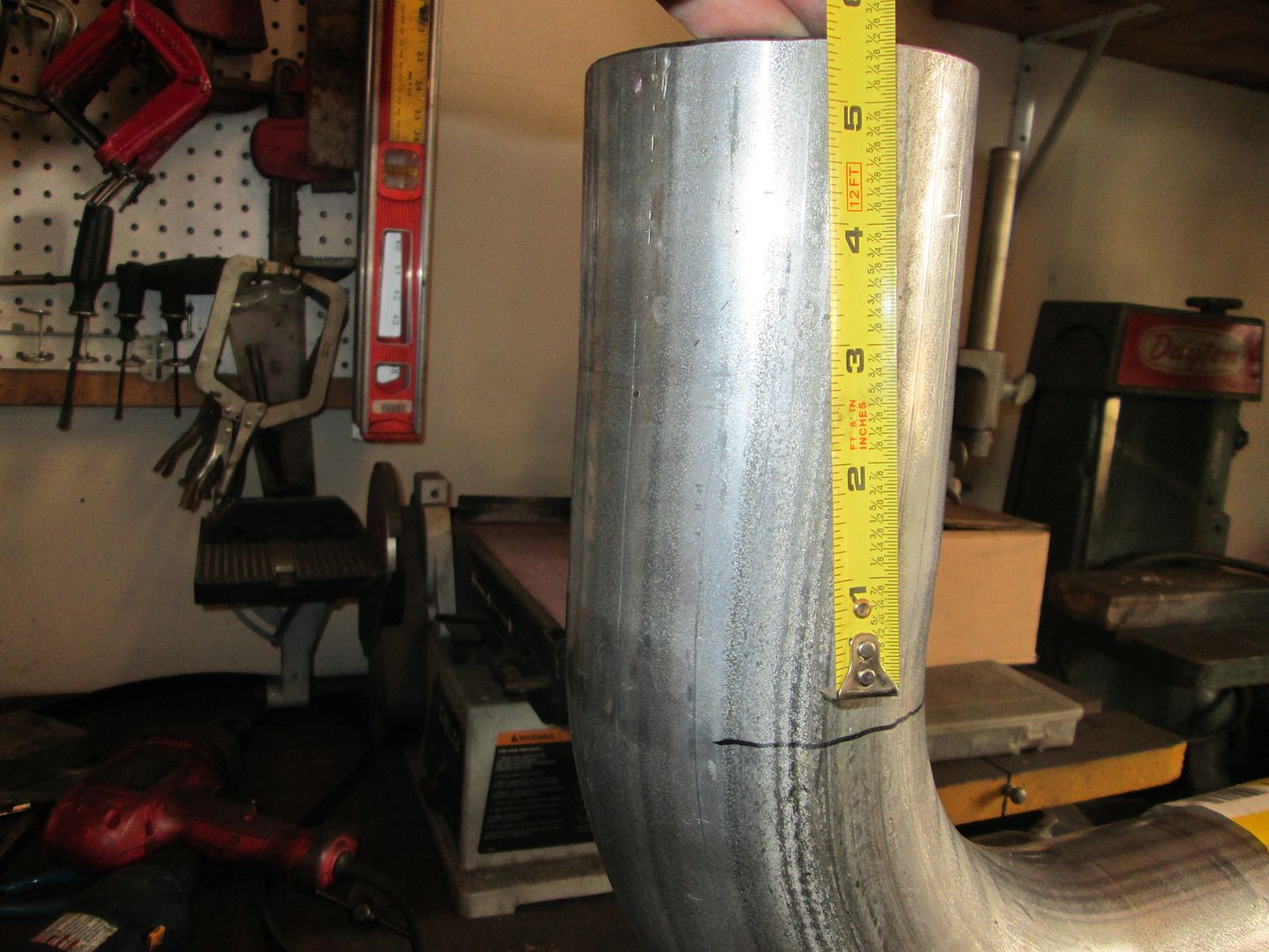
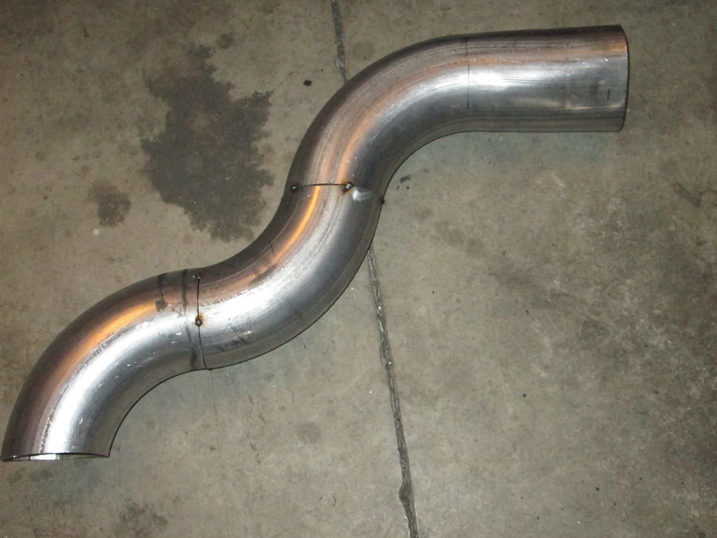
Compressed the end so the tube goes from round to oval so it will be closer to the shape of the TPI throttle body:
Then lots of cutting/test fitting the three different 90 degree bends to make this:
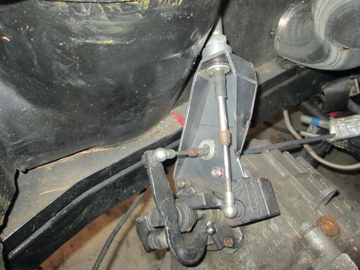
The shifter is hooked up and smoothly shifts to all gears:
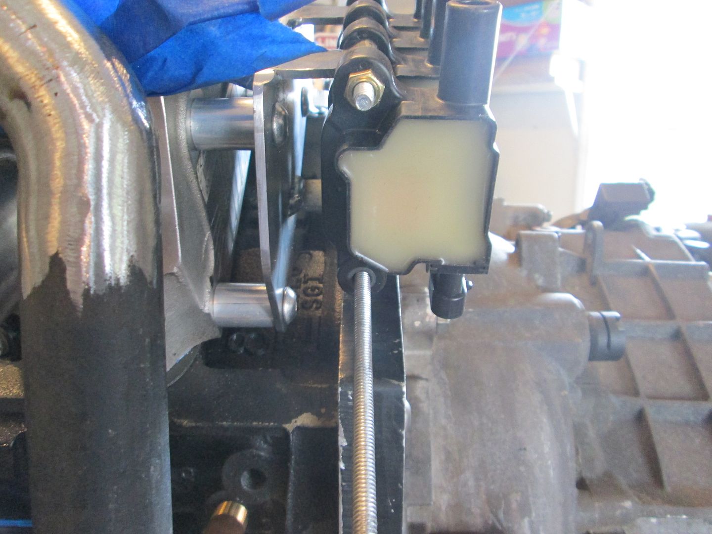
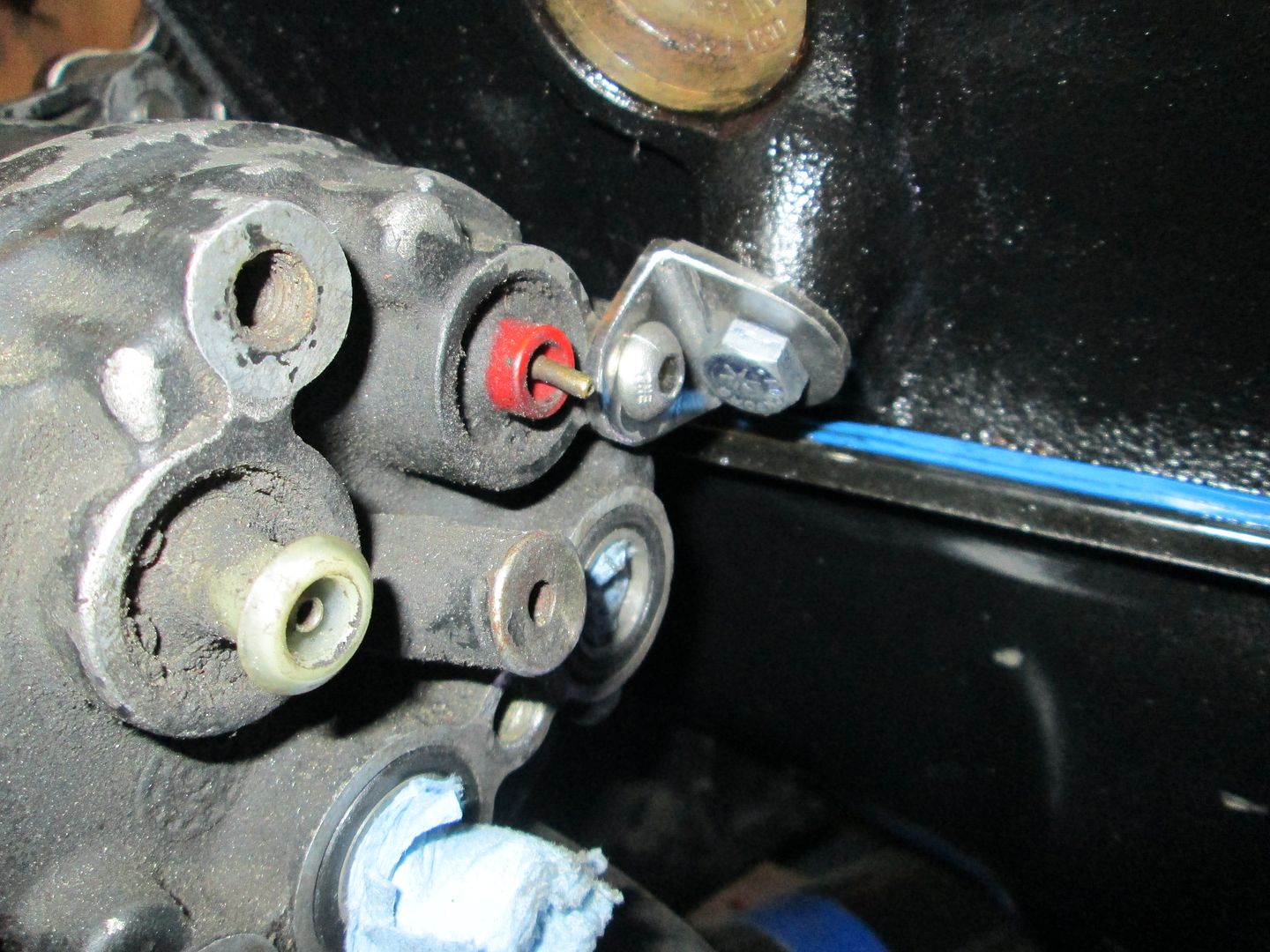
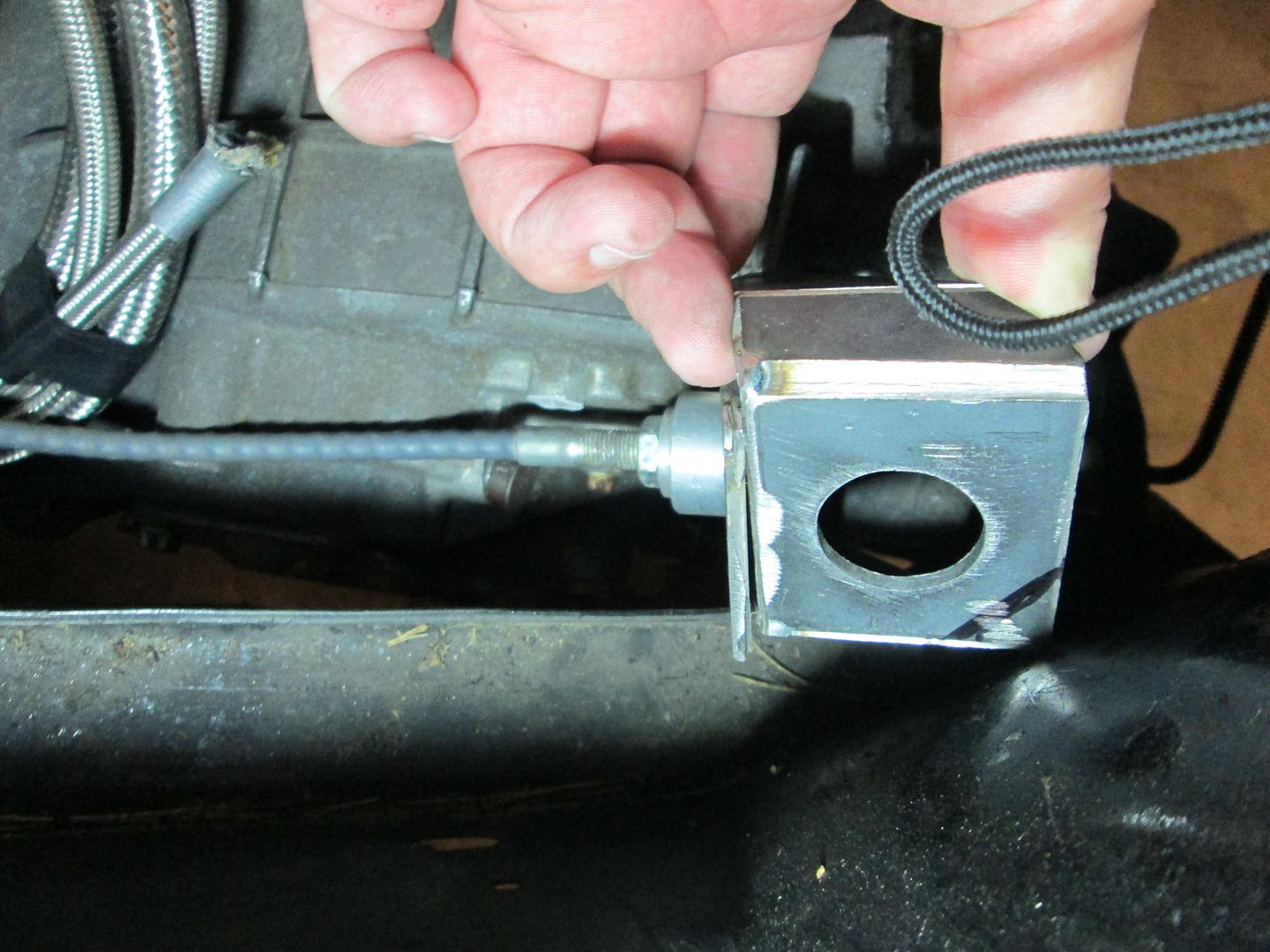
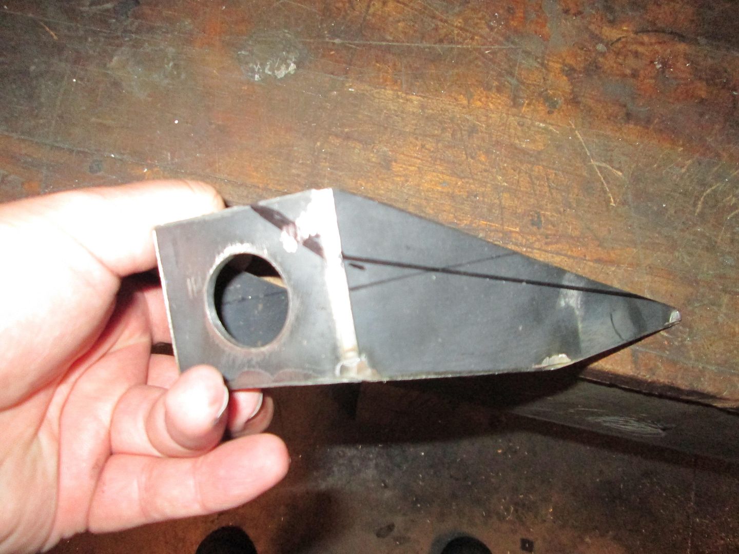
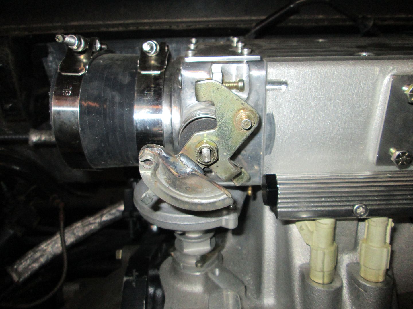
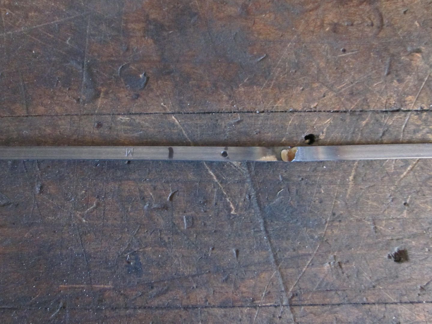
Then I pulled the console/skeleton out so I could swap out the throttle cable to an 88 4cyl one that is longer. Then I started to mock up the cable and noticed that the cable cam that was welded onto the throttle body wasn't properly centered and wasn't working with the available travel. Here is what it looked like before I modified it:
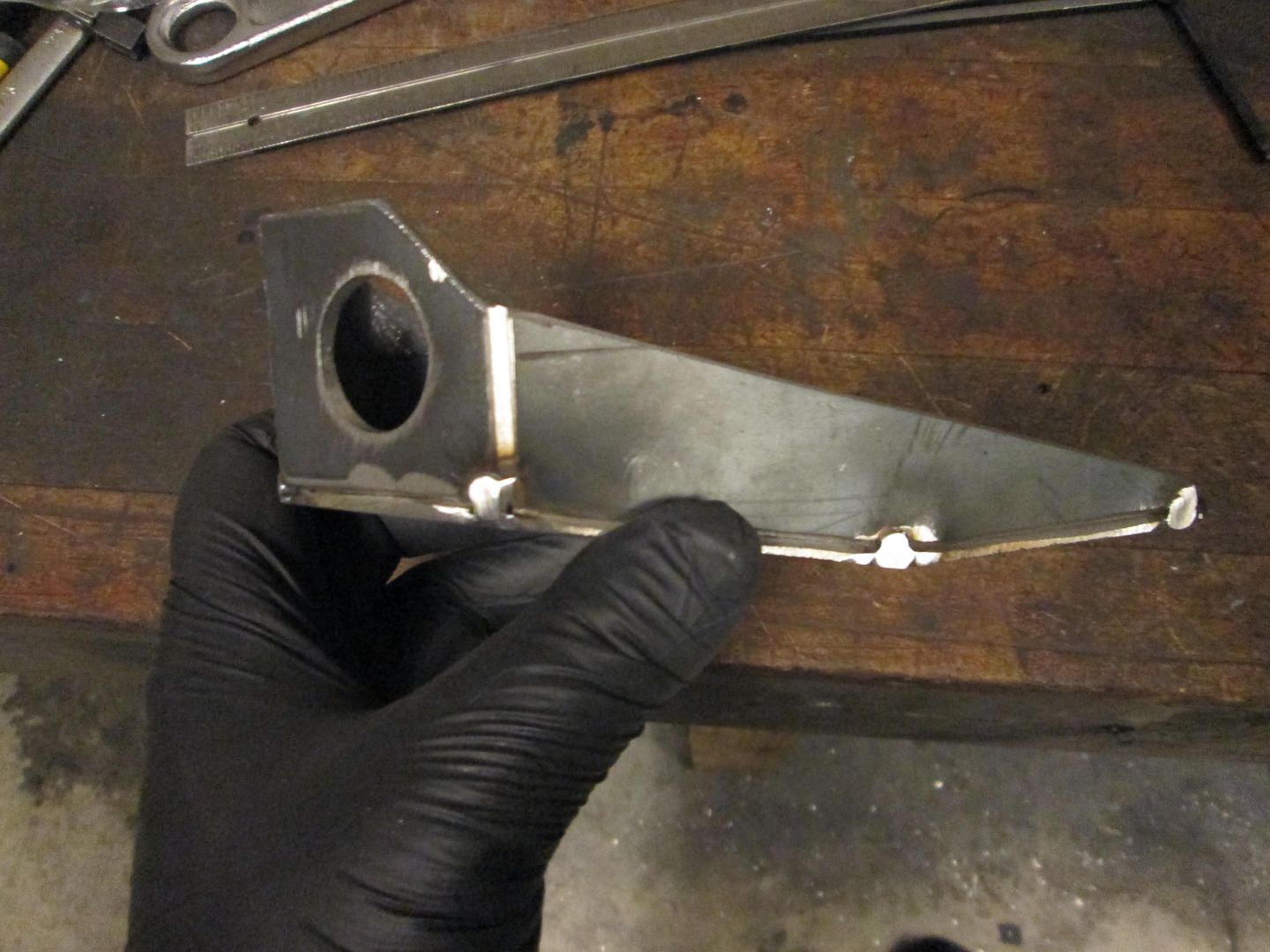
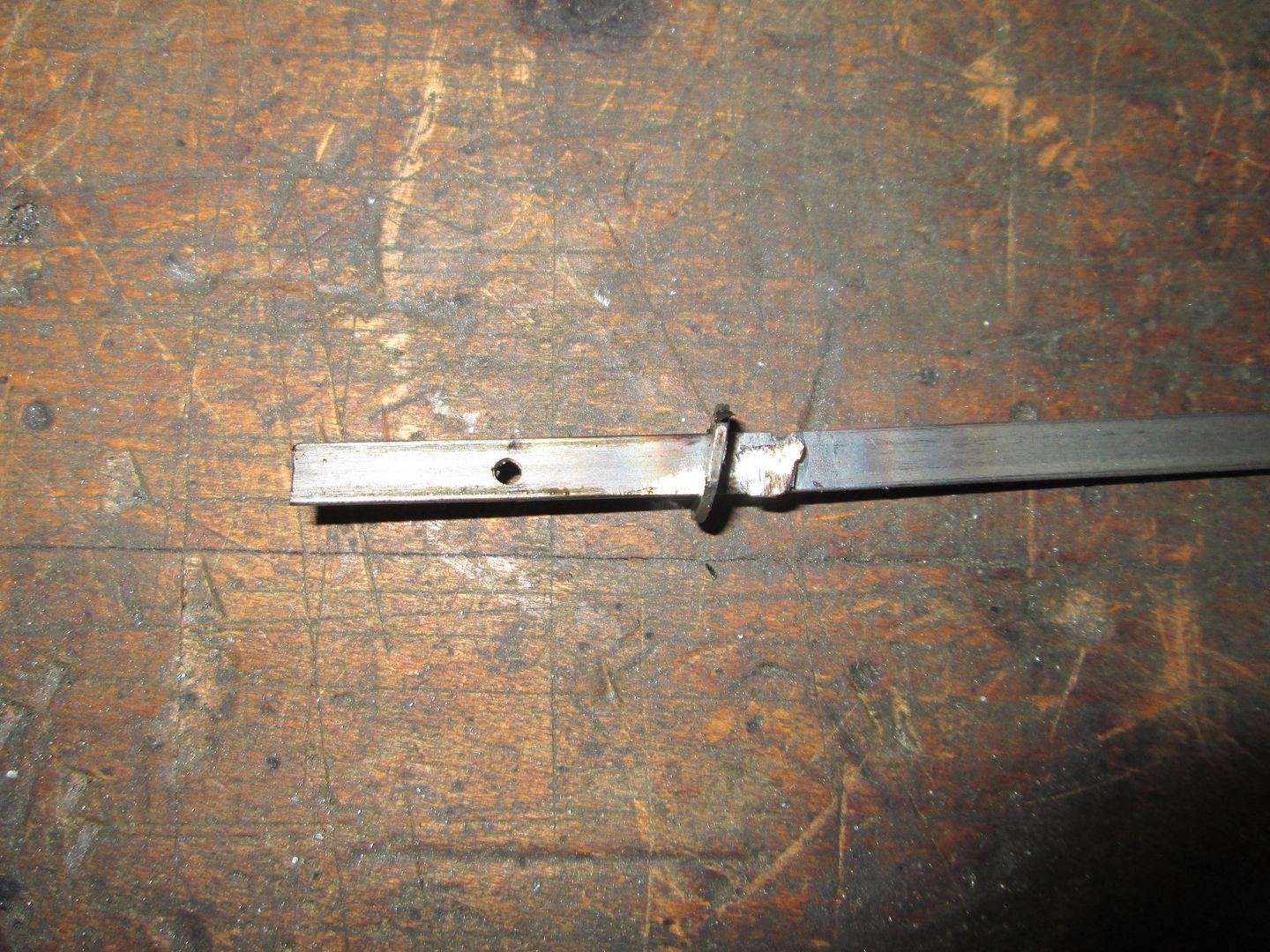
Then I cut it off, repositioned it and welded it back together:
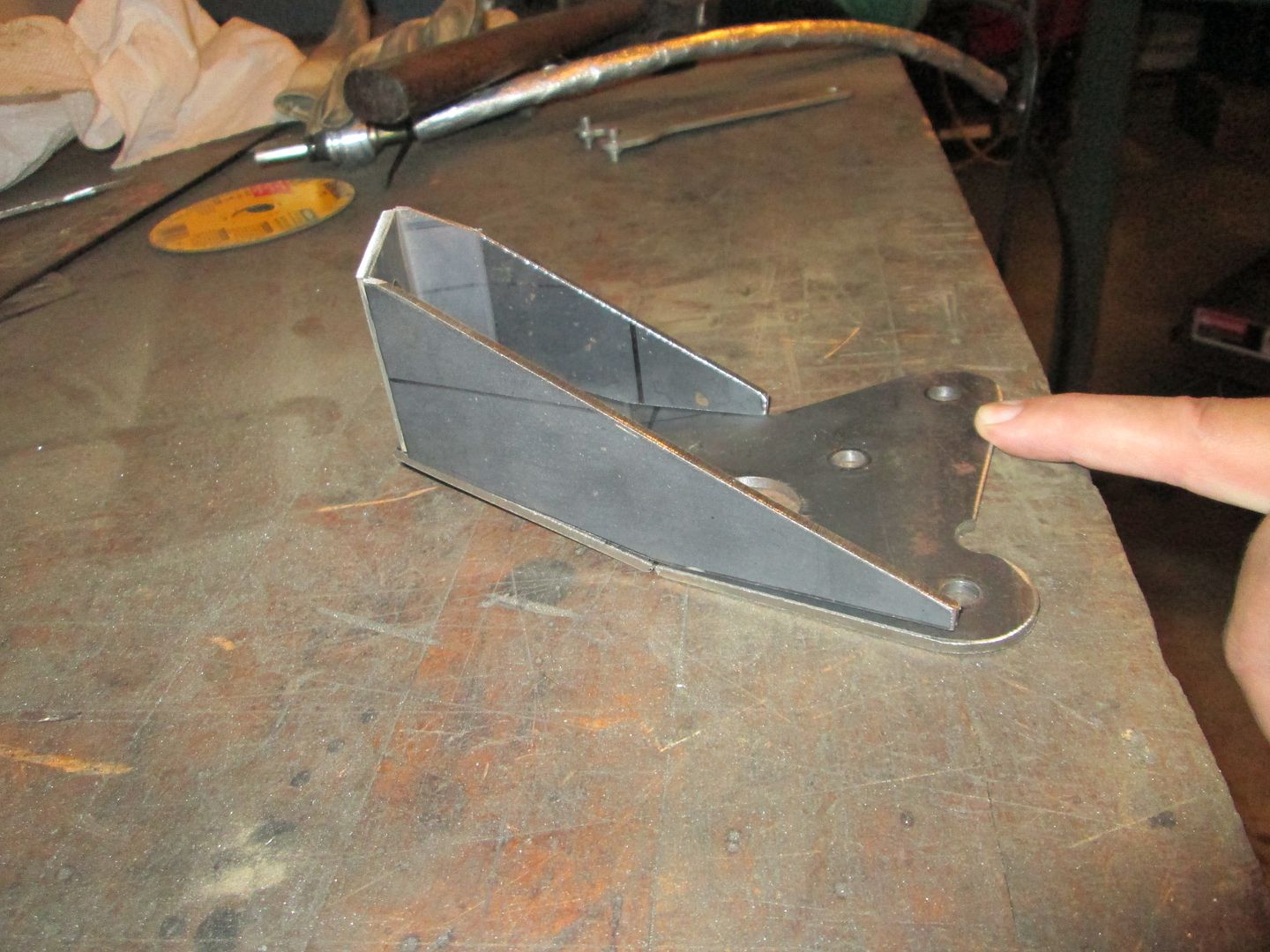
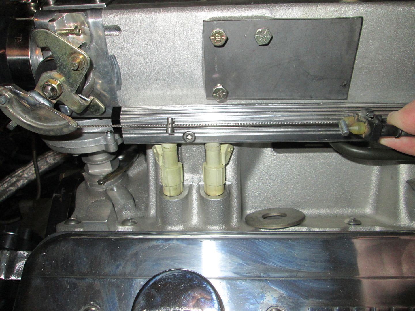
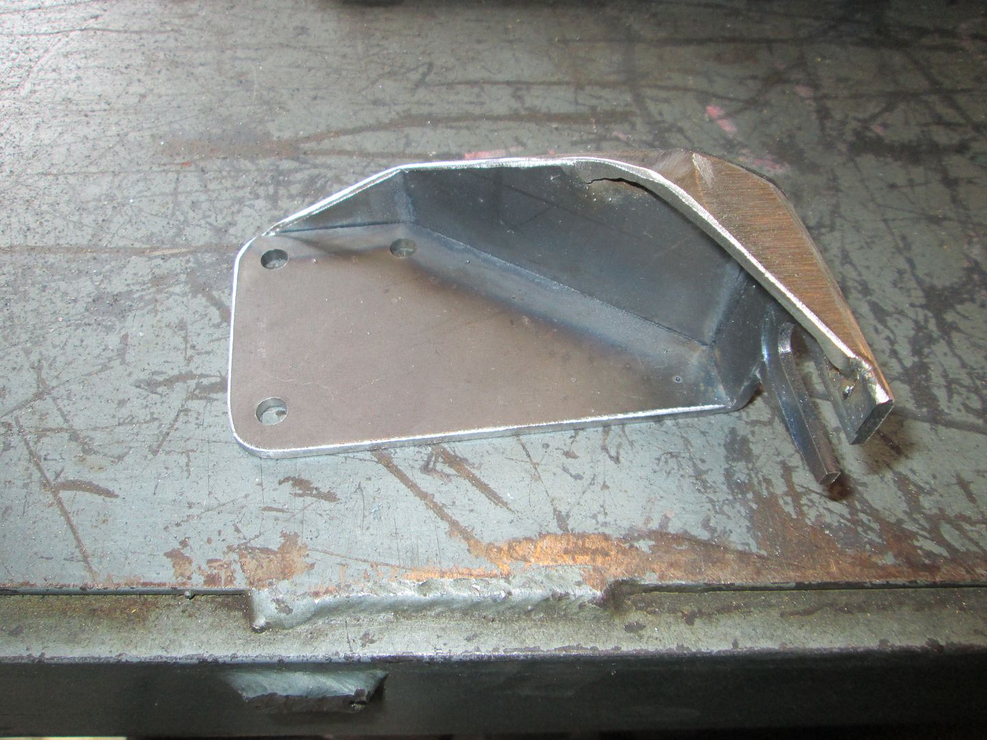
Here is a mockup with the cable and just starting to cut the material for the bracket. I will likely trim off the extra barrel end:
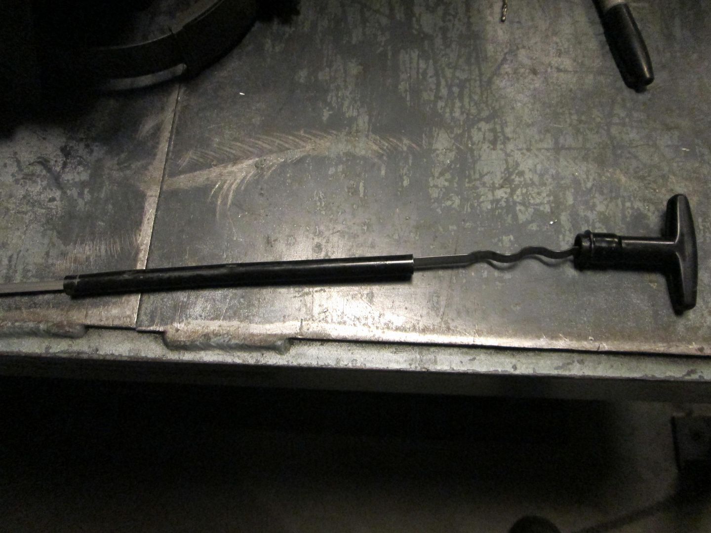
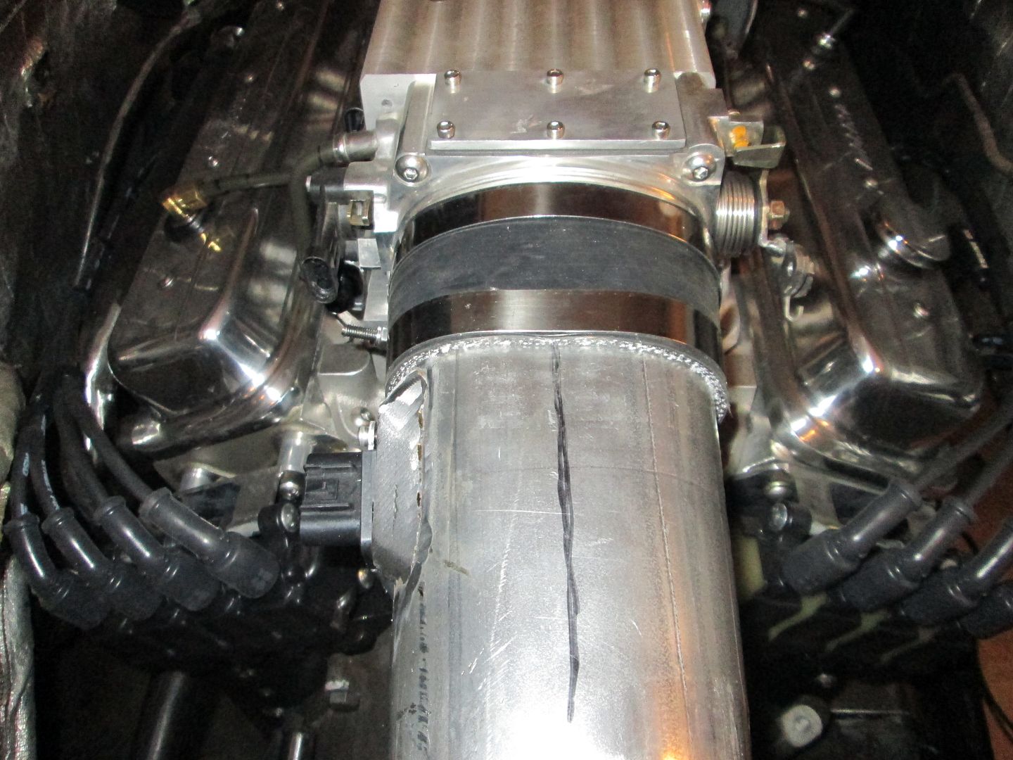
using the section of the tube that was removed, mark the new hole location, drill hole, mark the new cut line, and place a tack weld where the seal retainer ring goes.
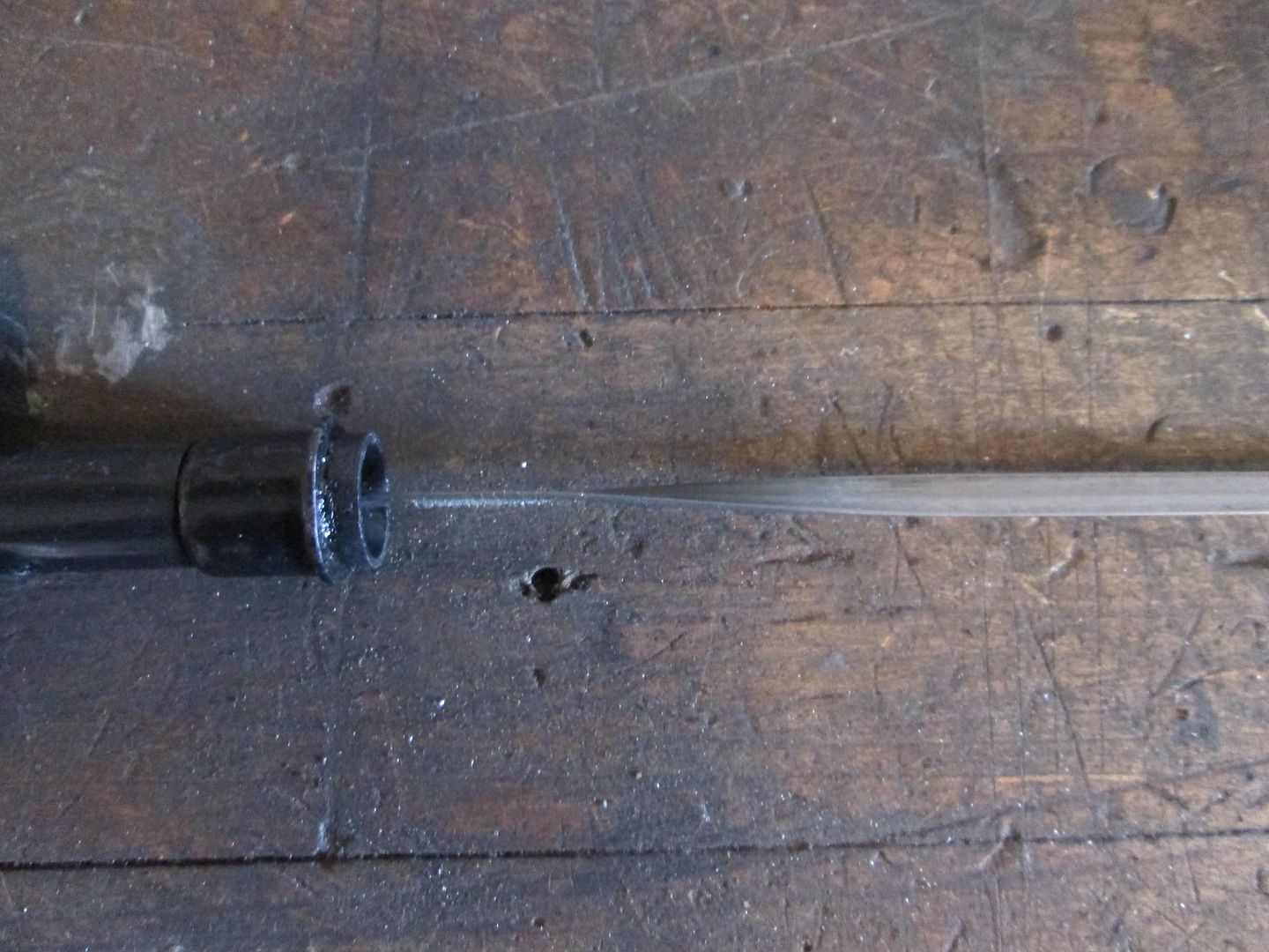
Install seal retainer ring:
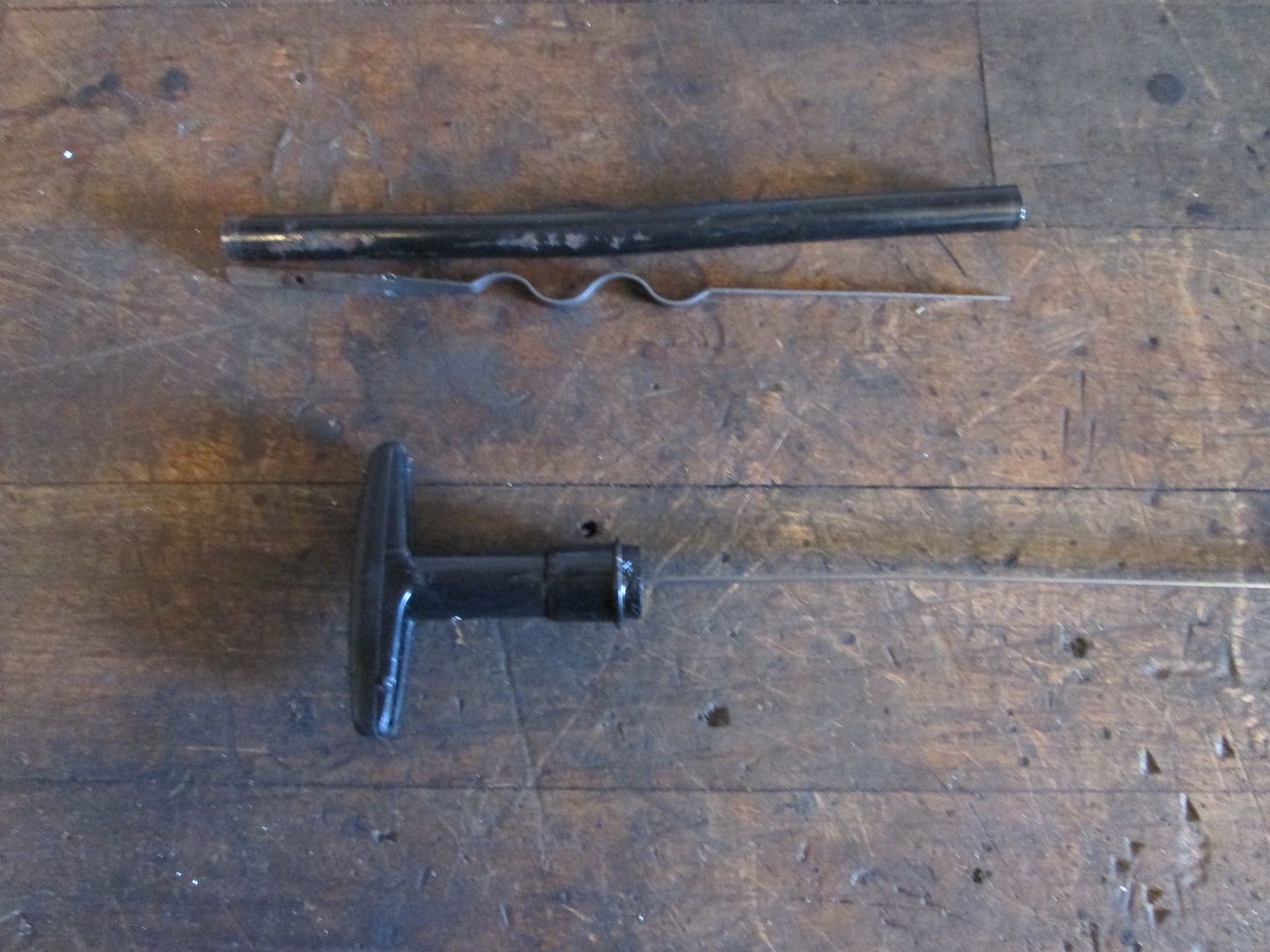
Install seal sleeve, handle and press in the dowel pin. In this pic you can also see the section of the tube and section of the banding that was removed::
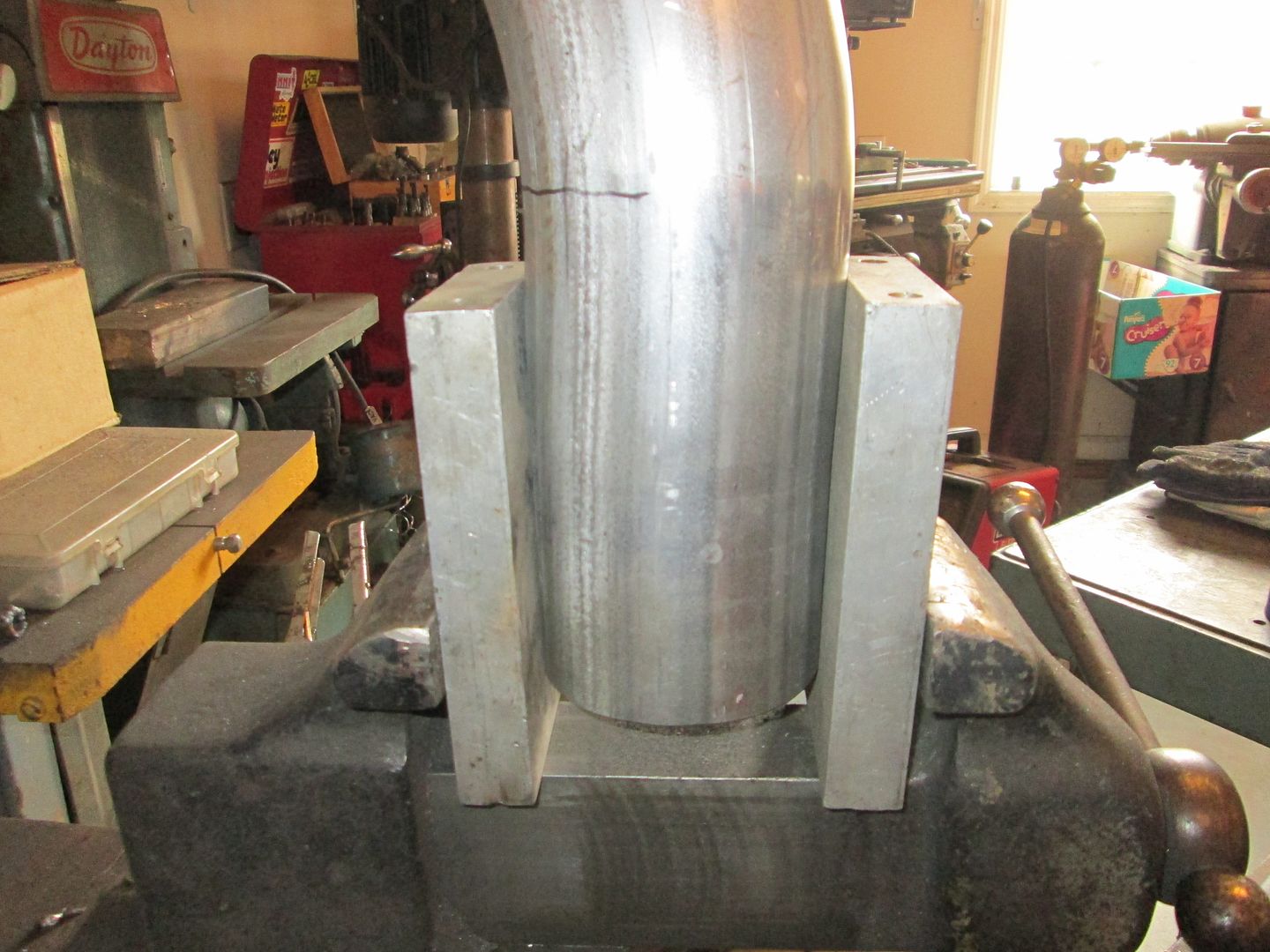
When I did a test fit in the car, the handle was perpendicular to the valve covers. Not really any issue, but I wanted it parallel, so I put the banding in the vice and used a crescent wrench to twist the banding 90 degrees:
Welded up the shifter bracket and smoothed the welds:
Welded up the cold air intake (still need to add the MAF mount):
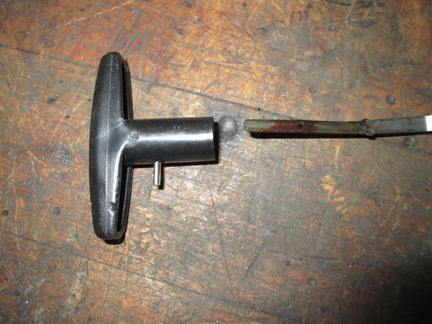
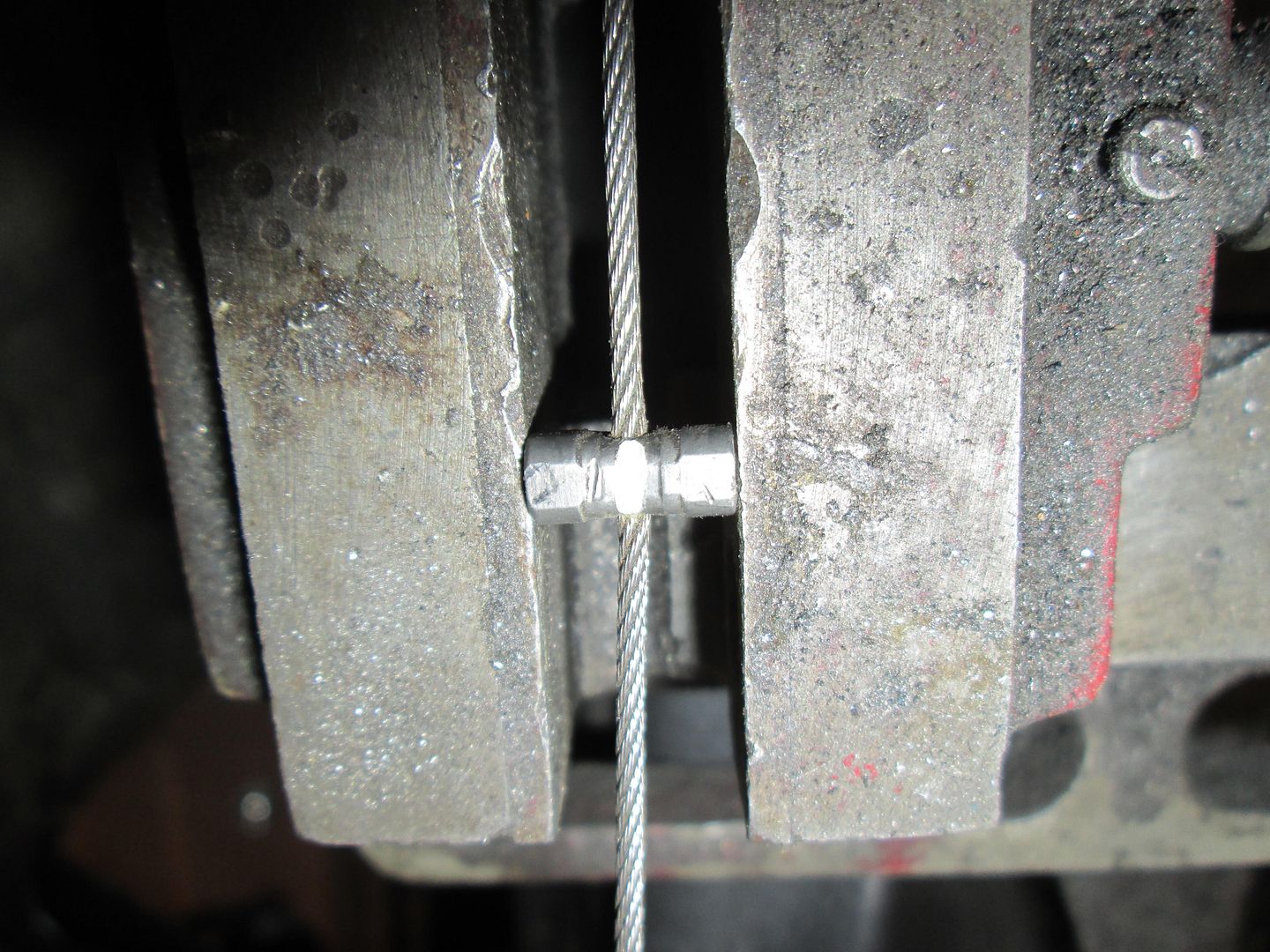
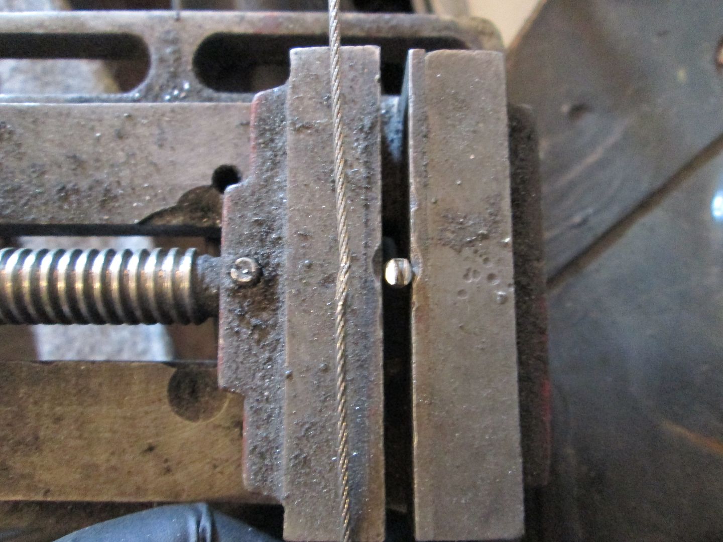
Removed the extra barrel on the throttle cable. I used my portable drill vice to hold the barrel, then carefully used a cut off disk to slit the barrel most of the way to the wire (but making sure not to nick the wire). I did this on both sides, then snapped it into 2 halves.
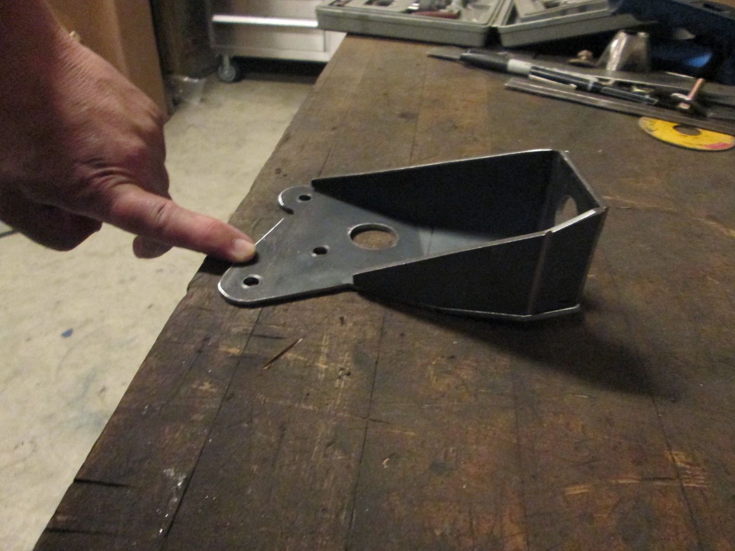
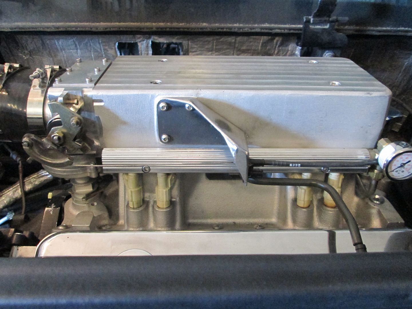
Finished up the throttle cable bracket, welded it and smoothed the welds. It used the factory style mounting and retainment for the 88 throttle cable:
[This message has been edited by fieroguru (edited 10-27-2013).]
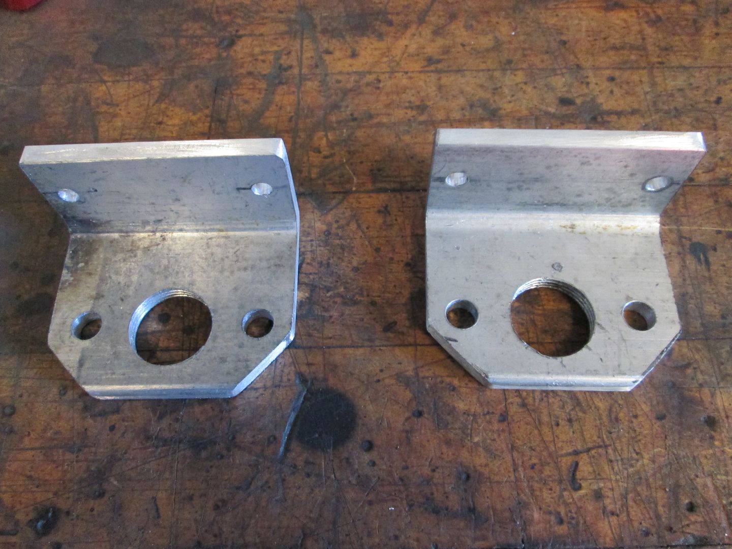
Been out of town for the last week or so, but finally got back to working on this car. Before I left, I had started making these aluminum angle plates so the water pump would have mounting brackets, and I tapped the aluminum for the A/N fittings:
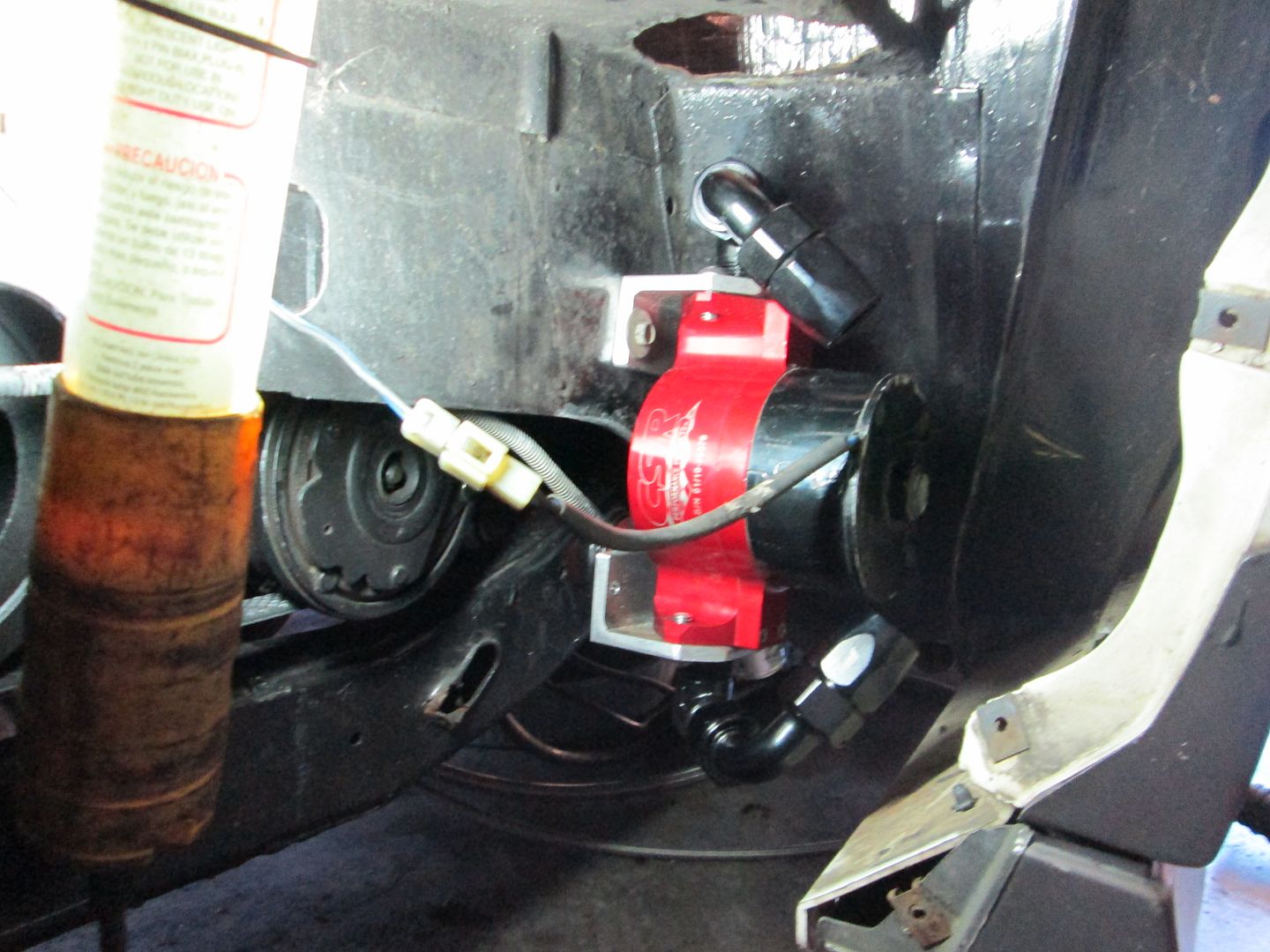
Here is the approximate location for the water pump. It is well below the water level in the radiator, so it should self prime when the radiator is filled.
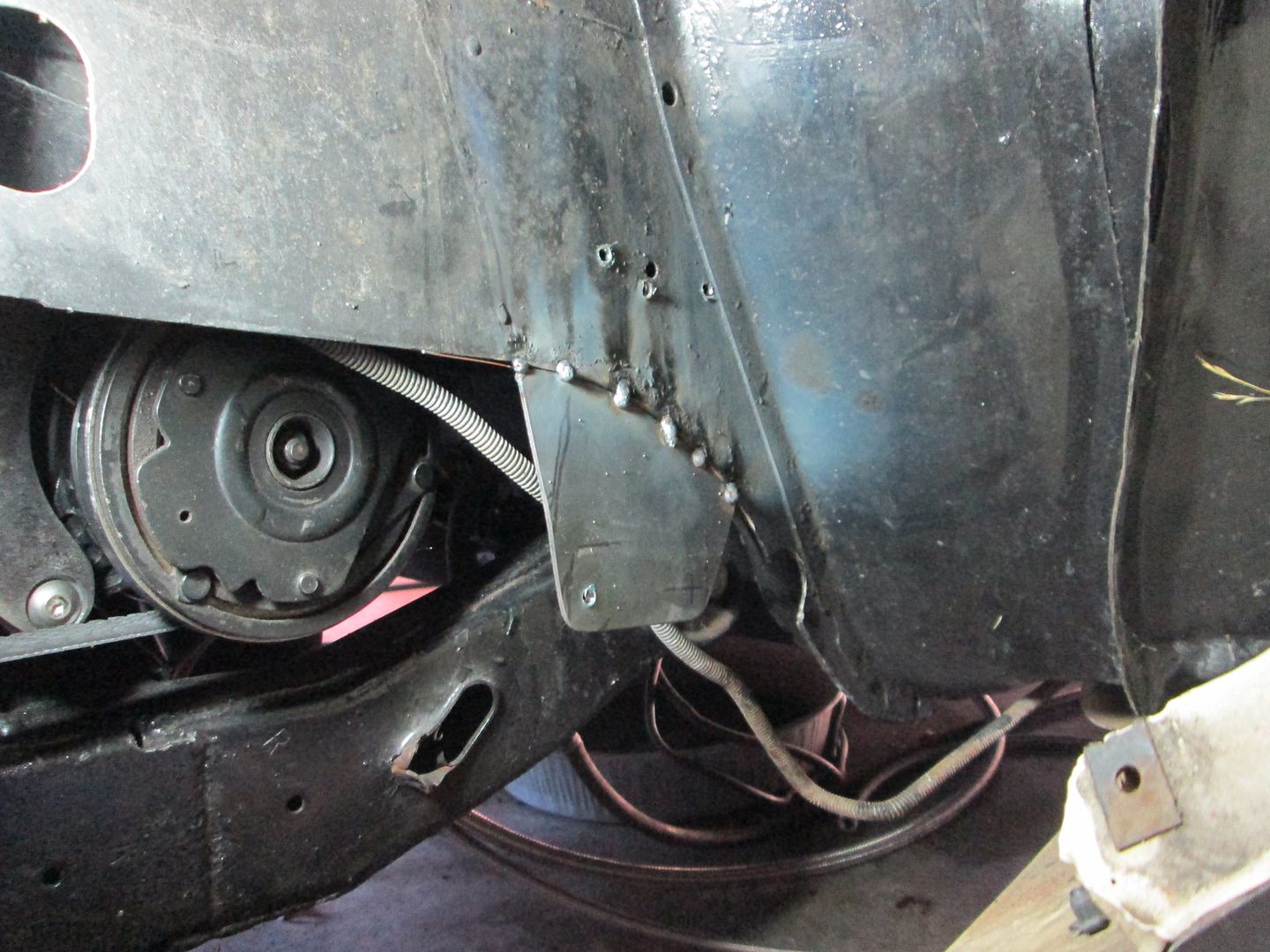
The bottom of the water pump wasn't supported, so I fabbed up a piece of sheet metal and tacked it into place. I will do more welding to it once the cradle is back out:
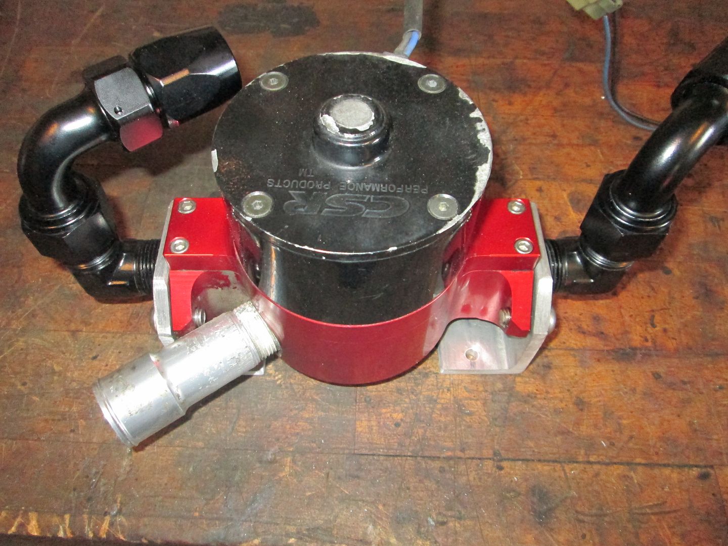
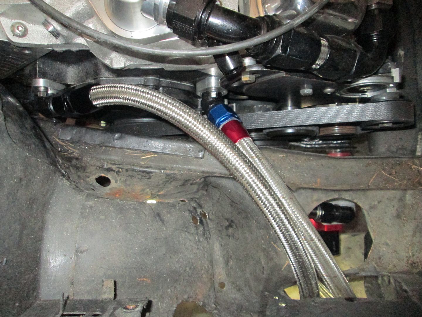
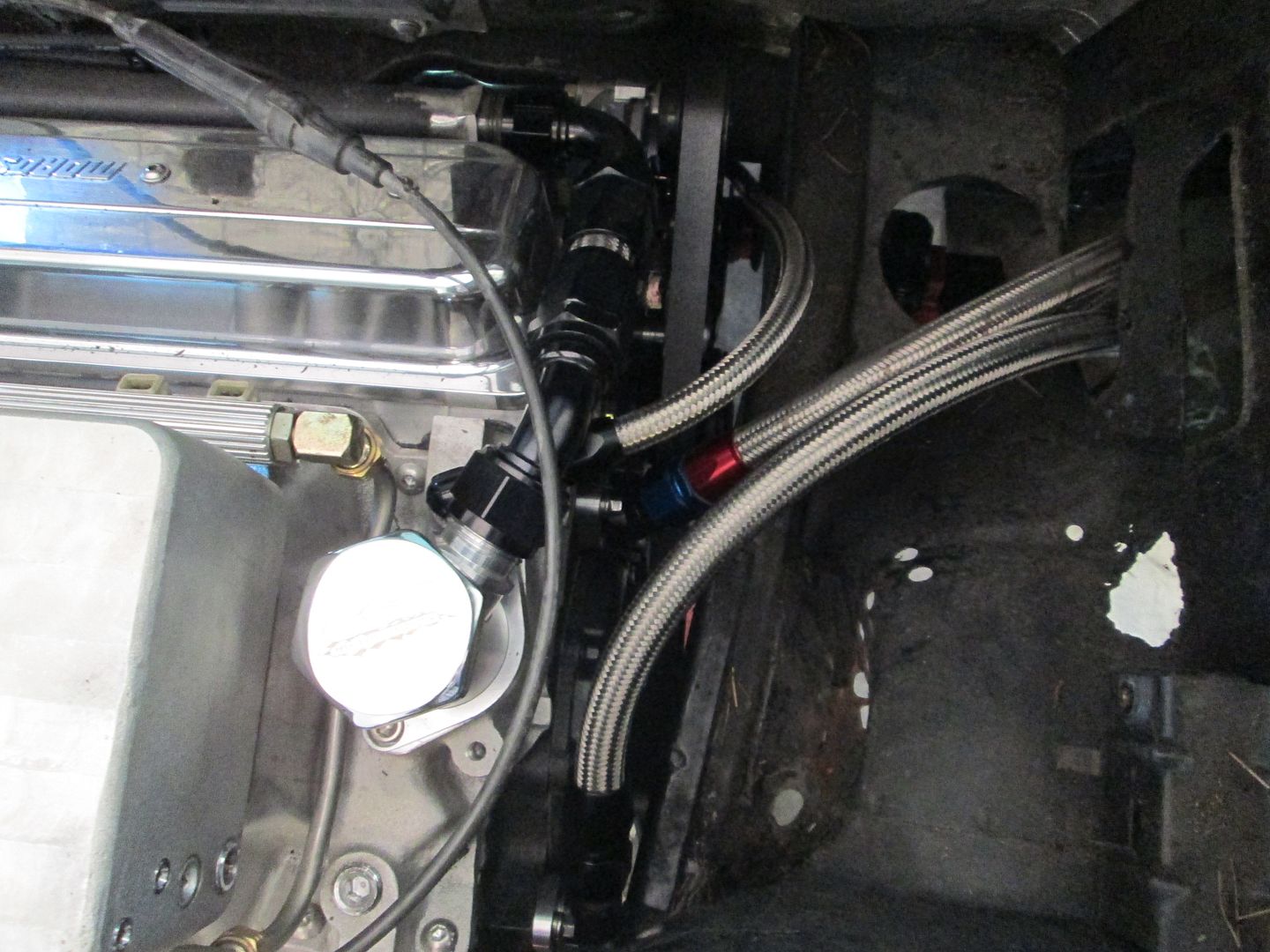
Then I started working on the braided stainless hoses. Here is one of the large hoses between the engine and water pump. The one with the red/blue fitting is just for mockup purposes (used), I had to order some more -12 hose for the other side:
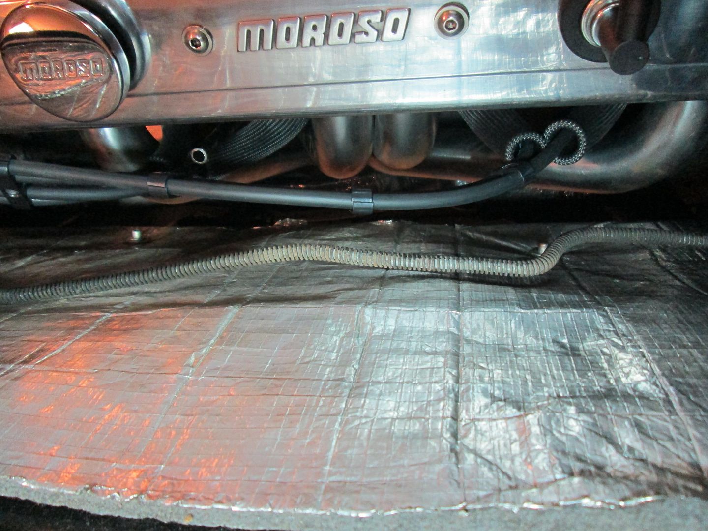
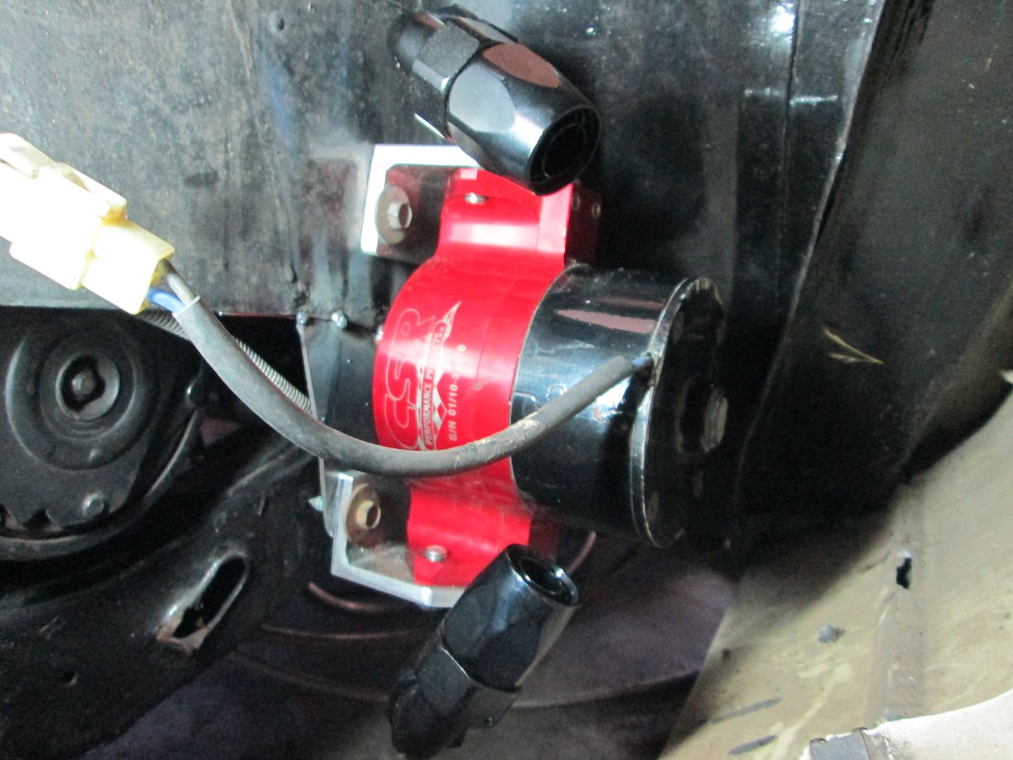
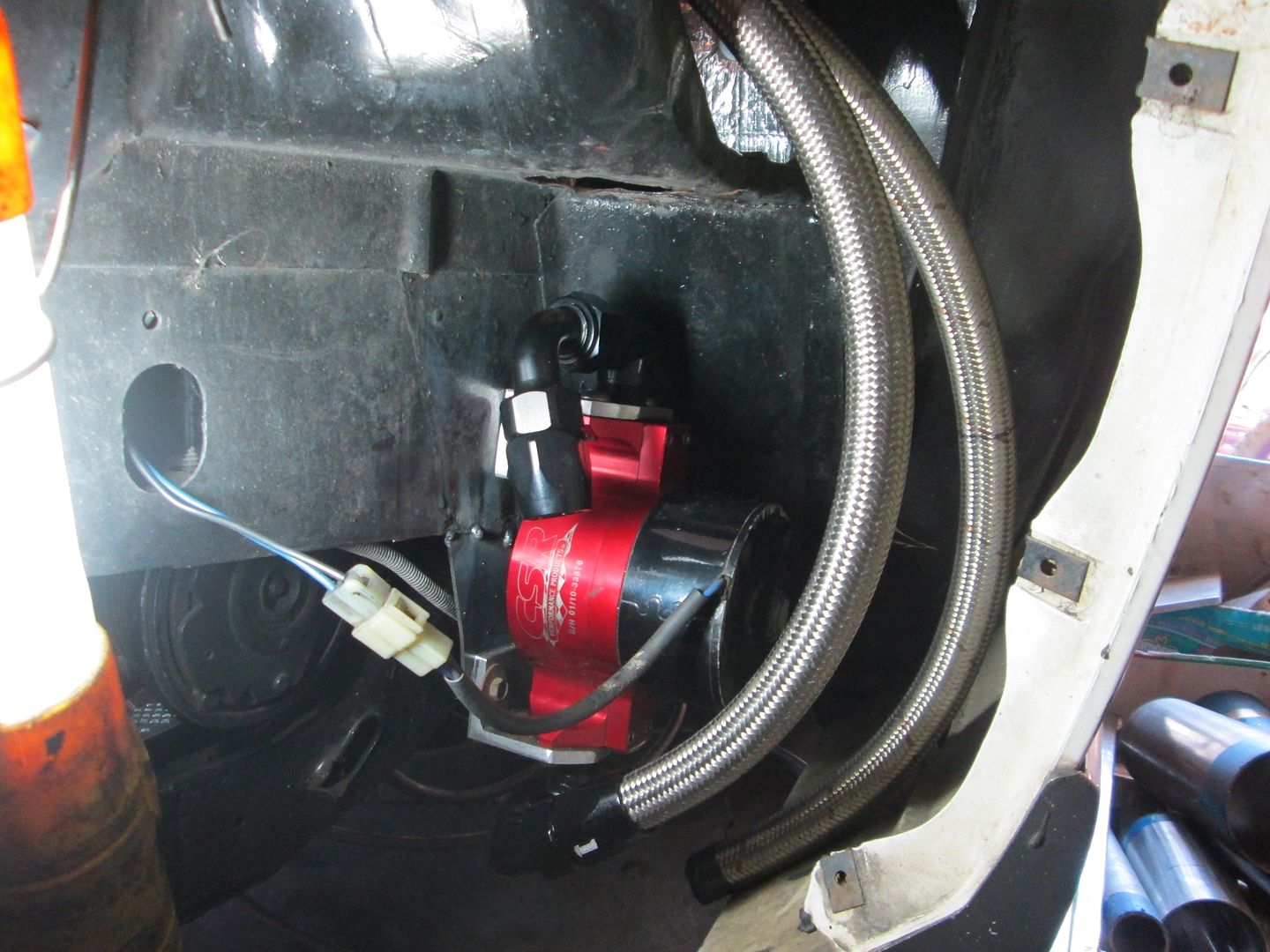
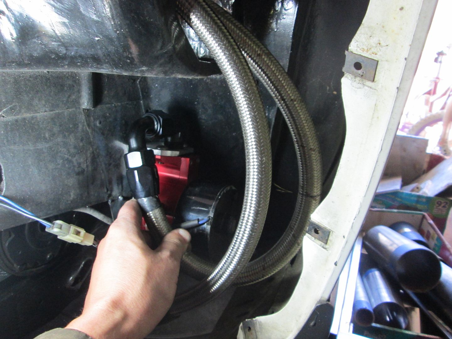
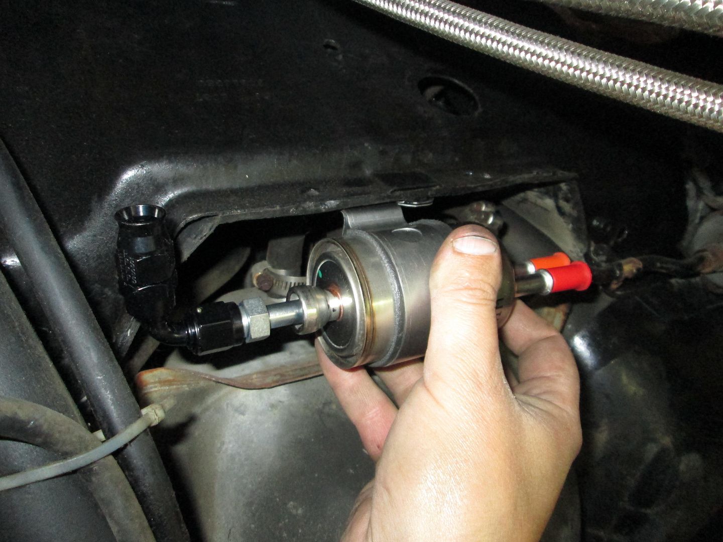
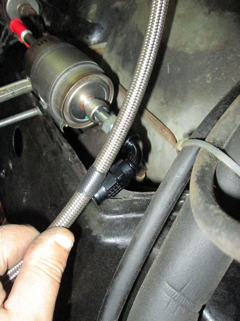
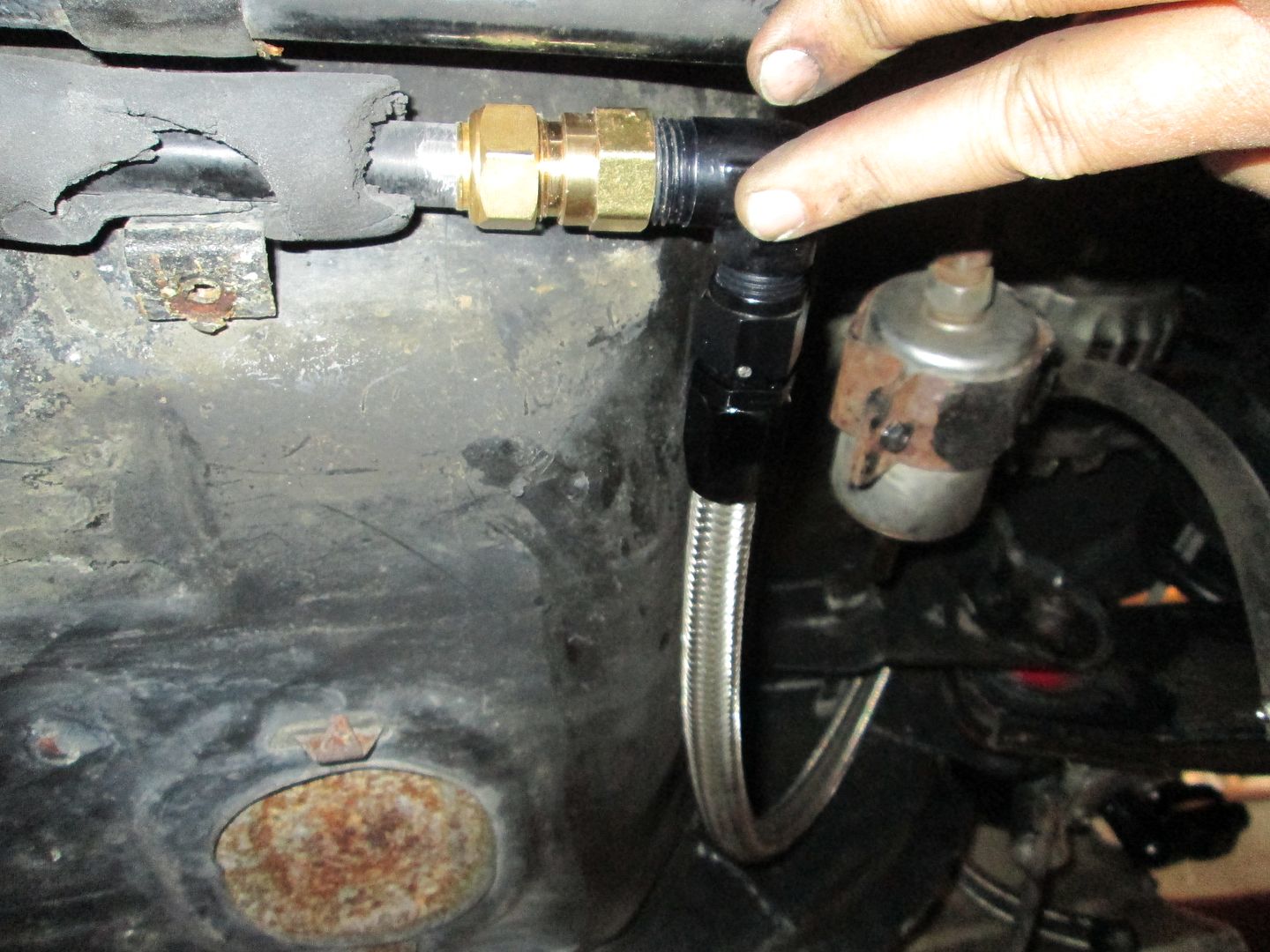
The new fuel filter/regulator will go in my normal spot, right behind the fuel tank.
Measured the hose to length and then remove it to put on the hose end:
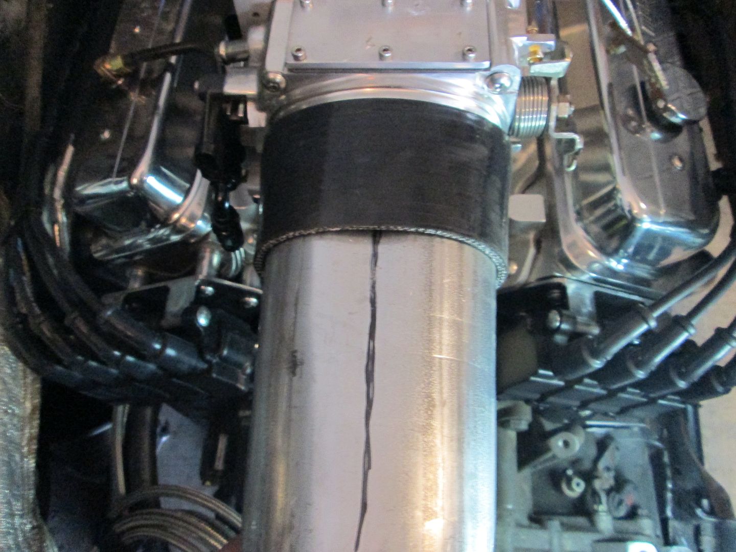
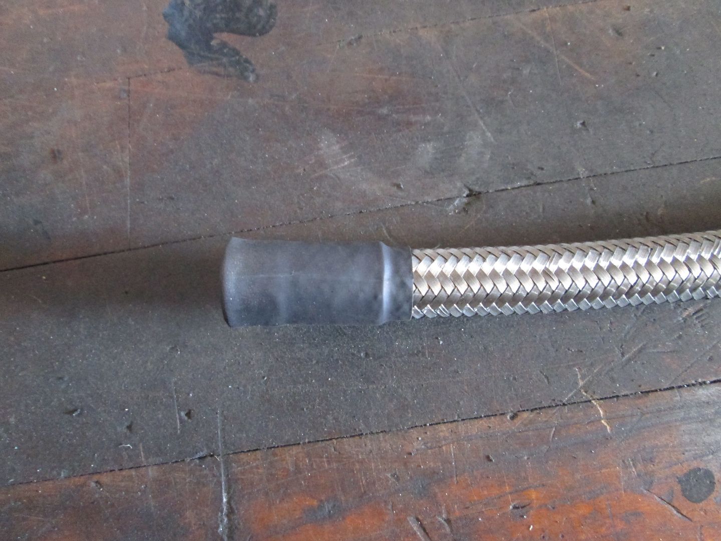
The brake booster hose was a little different. I had already installed the fitting on the intake side, but now needed to cut it to length and sleeve it so I can use a hose clamp to attach it to the brake booster hard line at the firewall. When I cut the hoses, I wrap the end tightly with electrical tape, then remove it to install the fitting. This time I removed most of it, but left about 2 wraps. Then I installed 2 sections of heat shrink and trimmed the hose again. Then installed the 3rd and last section of heat shrink and allowed it to overhang the end some to seal up all the stainless wires.
The heater hose supply hose was a little more involved. I trimmed the hard line, sanded it to bare aluminum, installed a 5/8" compression fitting, then a 90 degree AN fitting:
Braided Stainless hose central (ignore the red/blue mockup hose - it will be just like the others when done):
The other line (heater core return) will be routed into the passenger coolant tube (like the 88's) before the water pump, so it won't need to be routed into the engine bay.
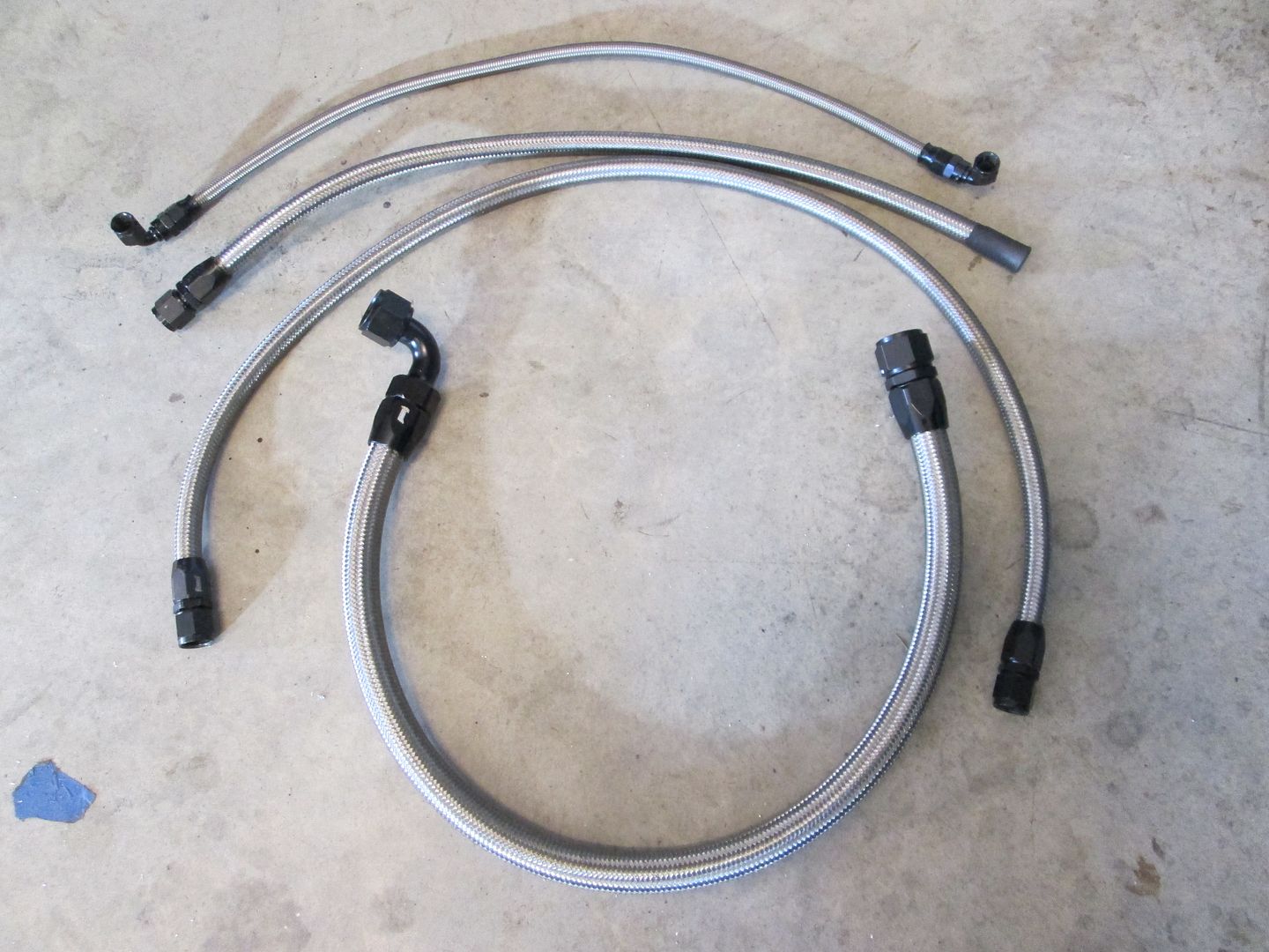
The braided stainless hose came in, so I finished making the last hose:
The connection from the coolant tube to the water pump will be a pretty simple hose to find (the coolant tube was trimmed back to its current location by previous installer):
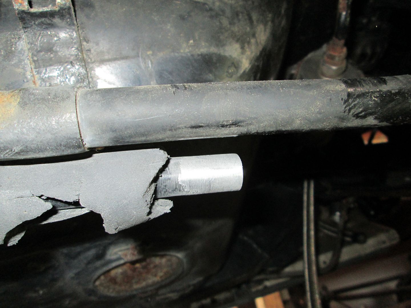
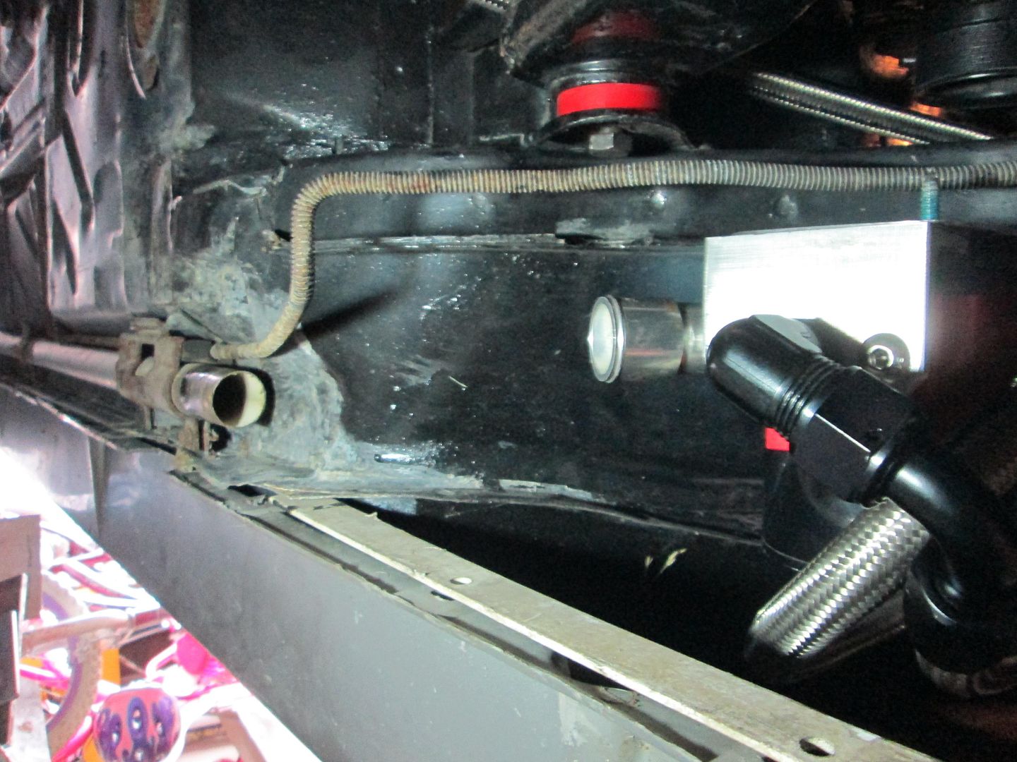
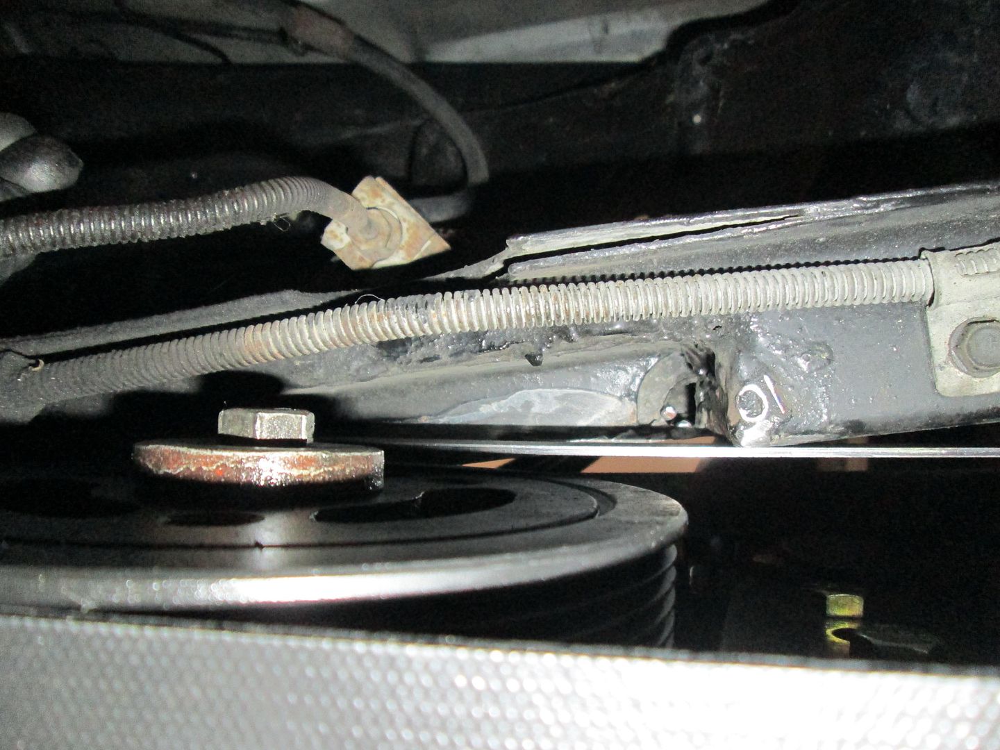
While under the car, I took a couple of pictures of how much I can close up the current frame notch. I used a straight edge to show the approximate location of the new metal I can add back while working on the engine bay:
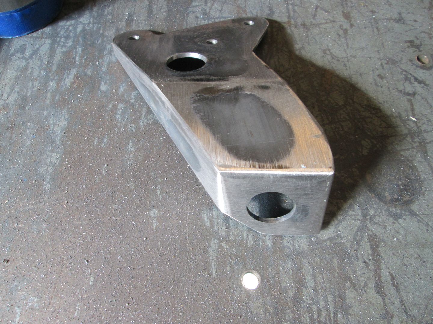
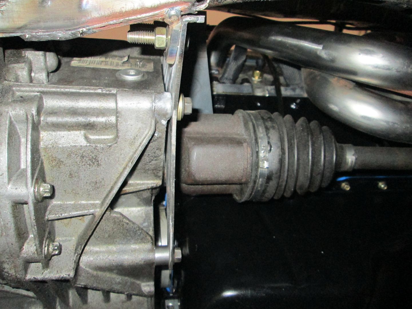
I never took a picture of the boss I added to the rear transmission mount:
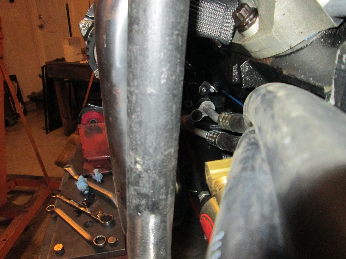
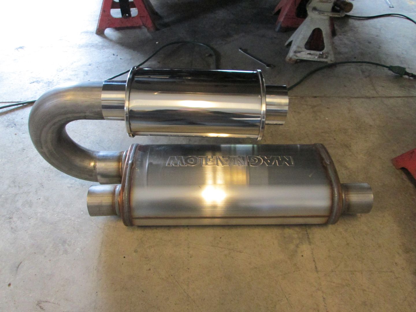
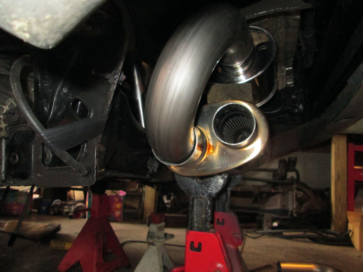
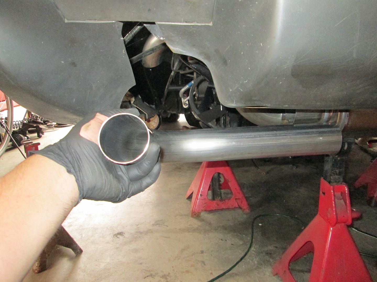
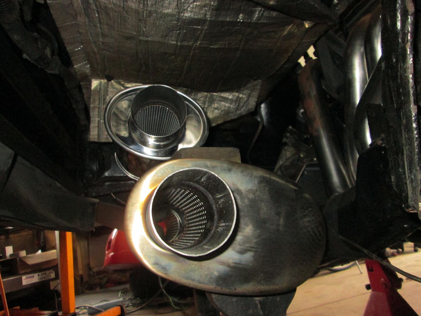
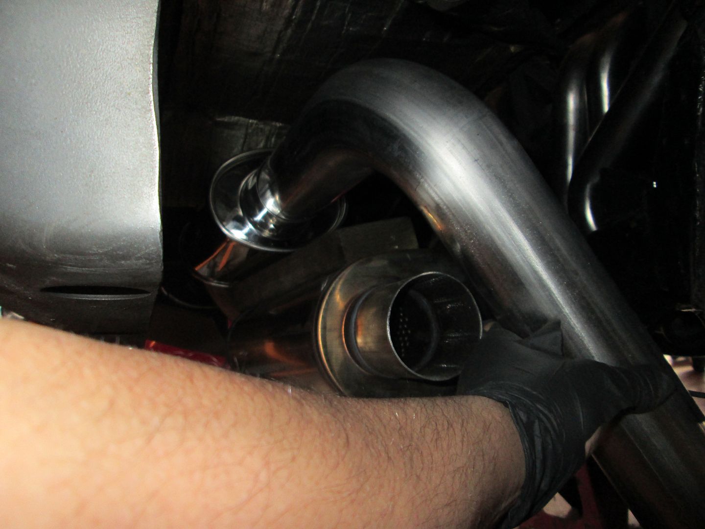
Then I did a little mockup of the resonator and muffler to see how much room there is (quite a bit with the trunk already having been removed):
Fabbed up the MAF mounting boss for the CAI:
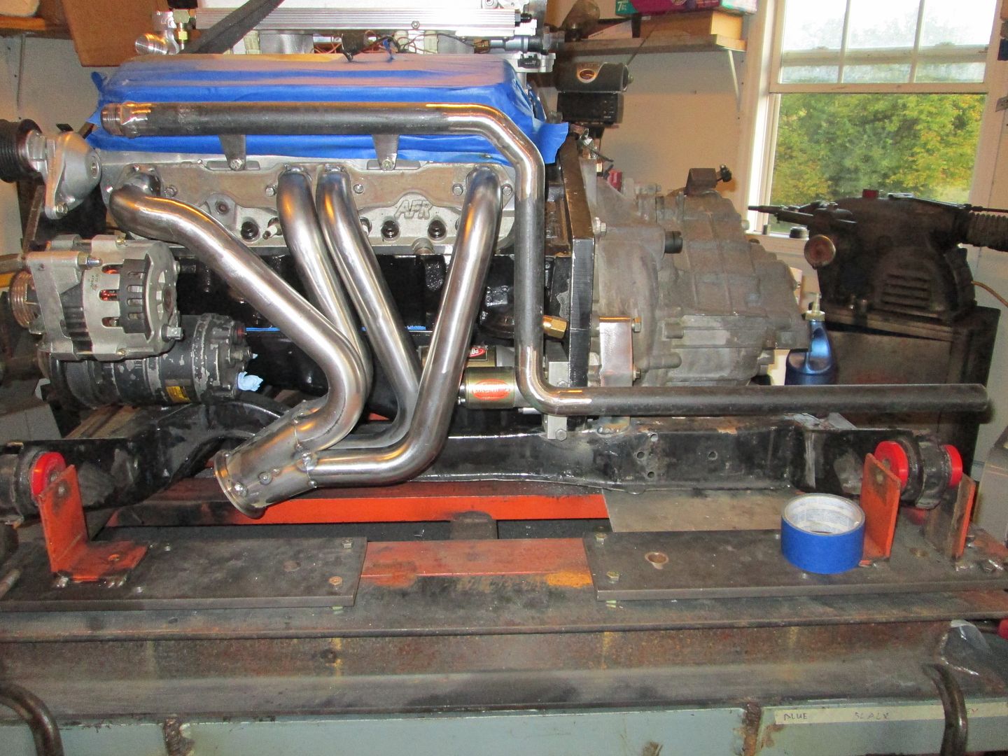
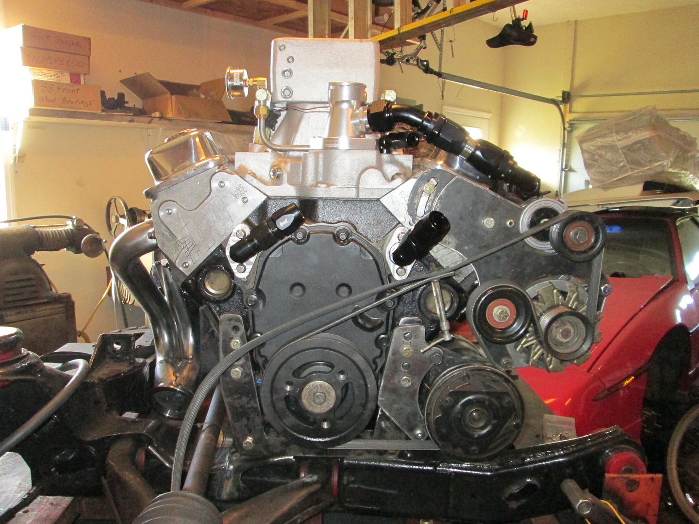
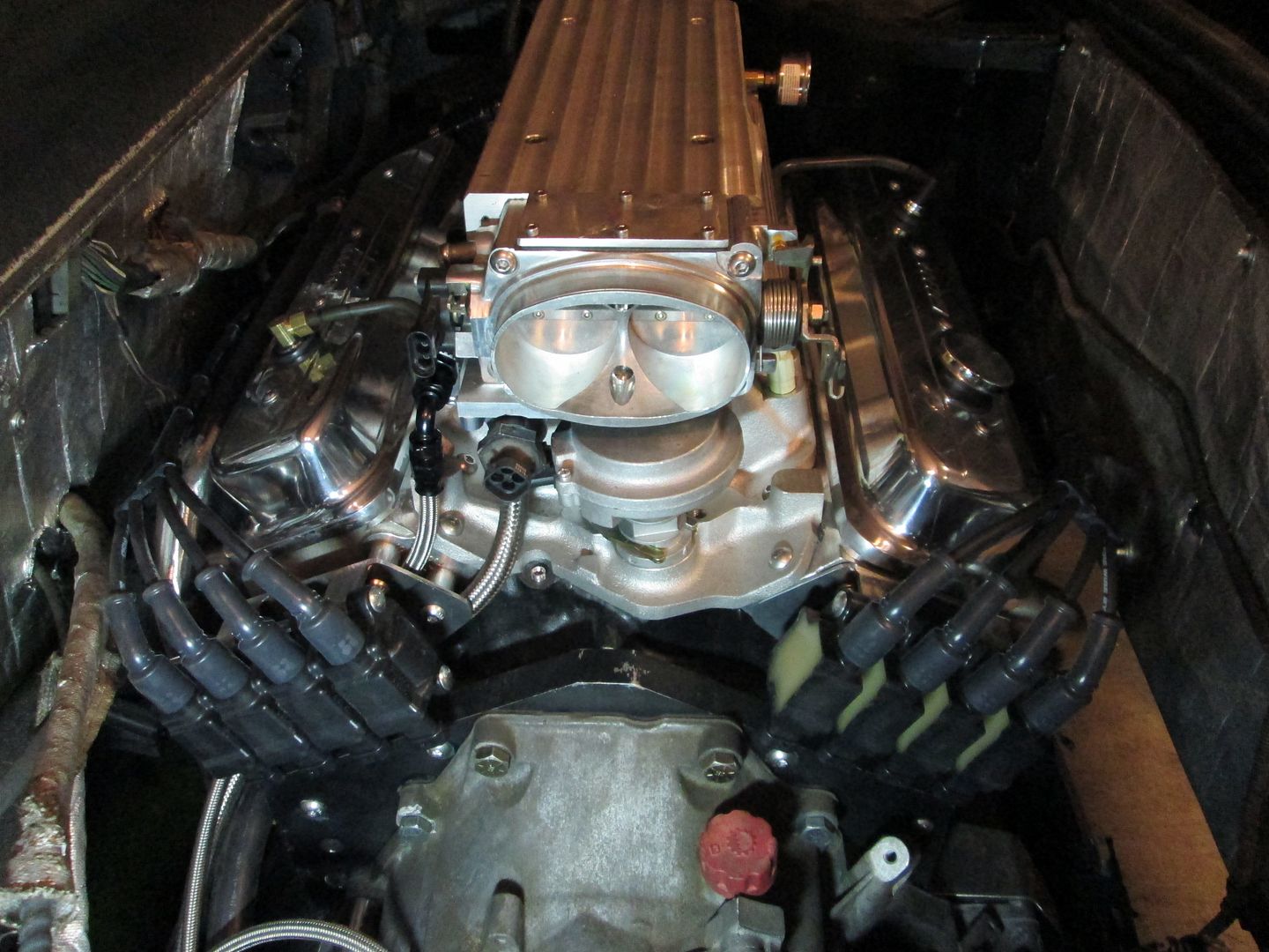
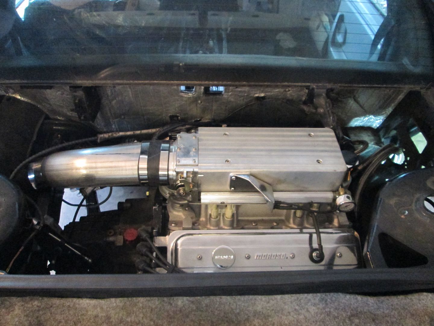
Here is an overall pic before I take it all back apart for engine bay prep, cleaning/painting:
"It's 3:30 in the afternoon, do you know how awesome your car is?"
Why yes, yes I do. Because Guru just put up a post showing off some of the kick-butt stuff he's done! And I got a peek of the setup with the new serpentine belt in place! Which made me really happy - something I definitely needed after the last few weeks (and upcoming 6 more weeks) of work.
Fabbed up the bracket to hold the oil dipstick tube:
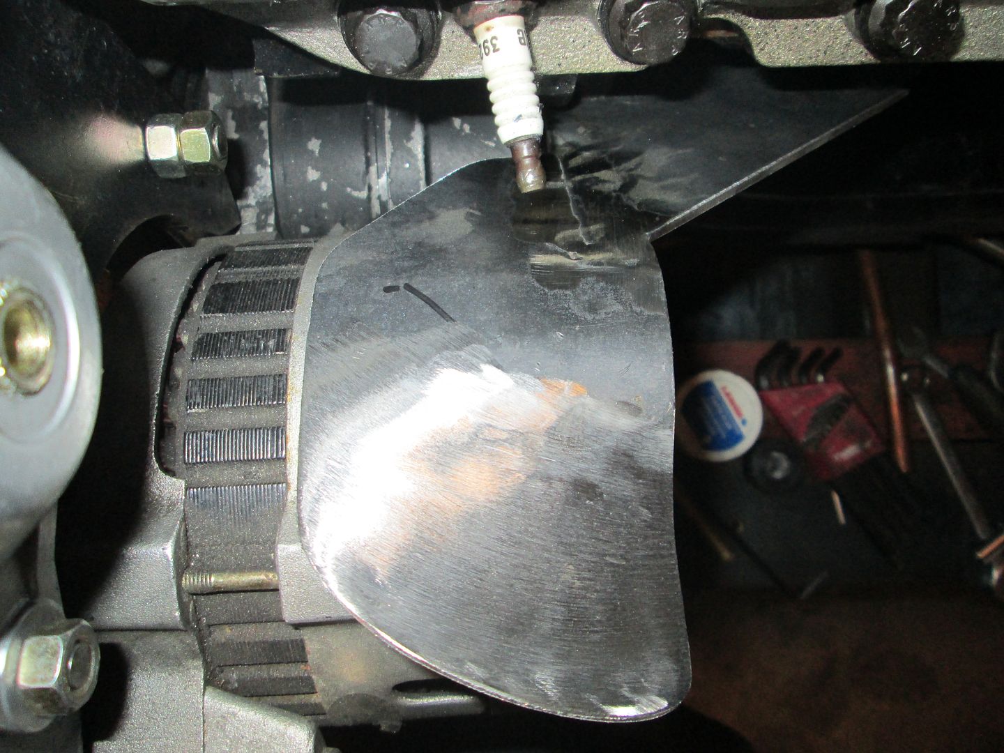
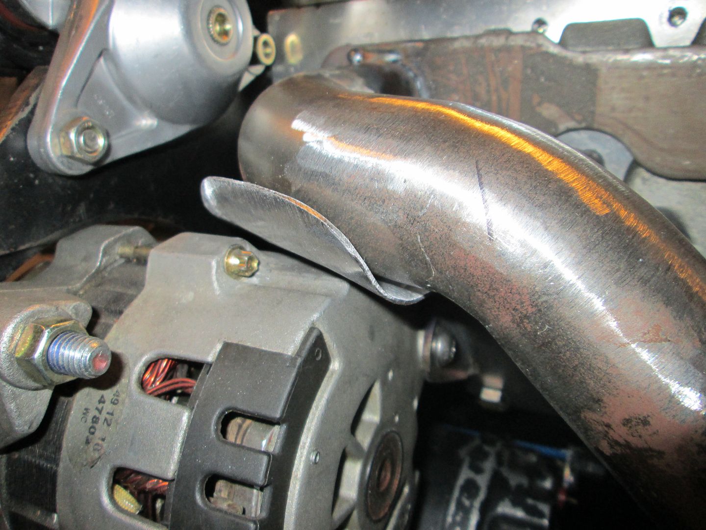
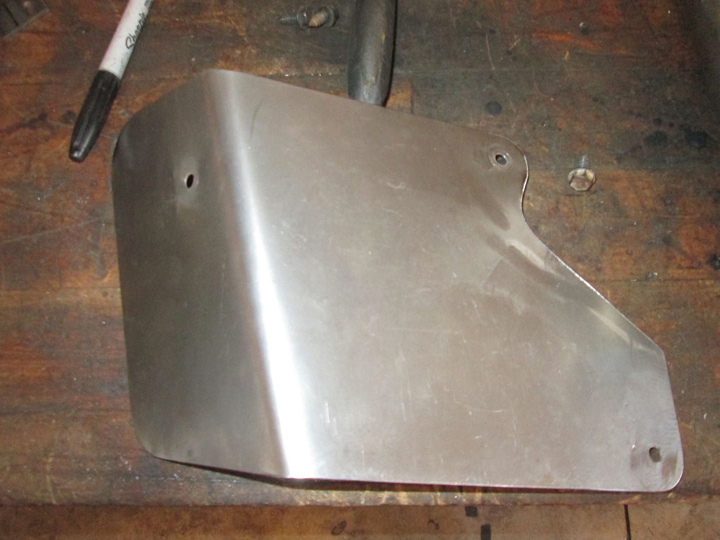
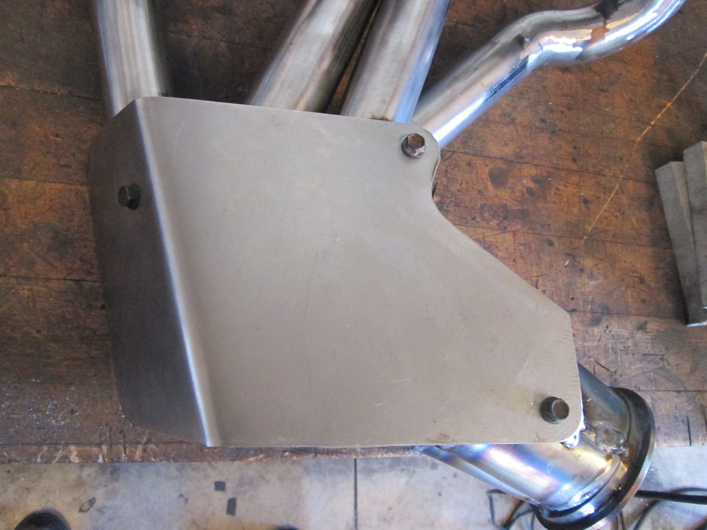
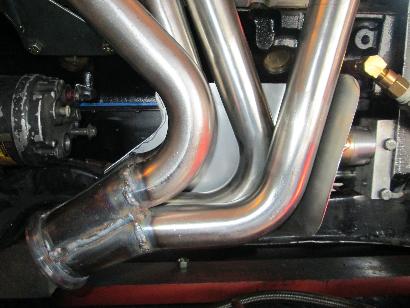
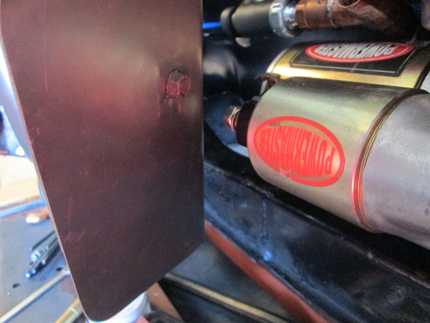
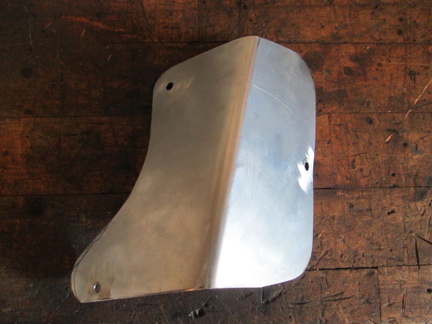
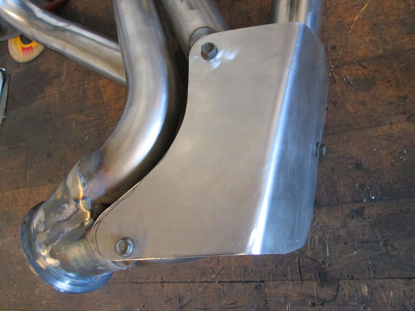
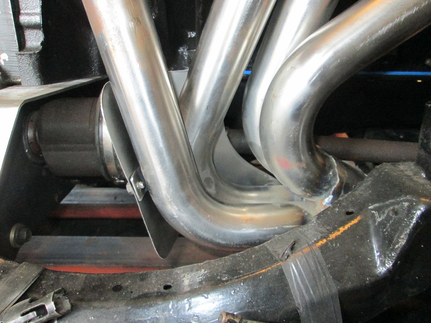
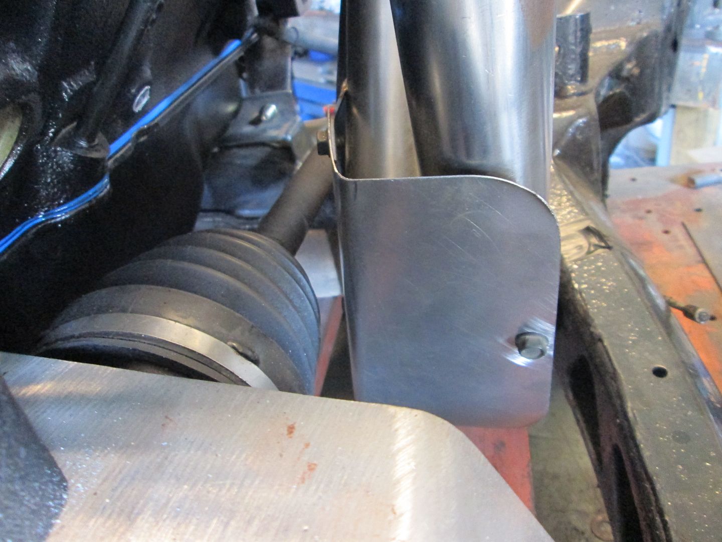
Worked on the heat shield for the alternator. I ended up adding it to the rear alternator support bracket:
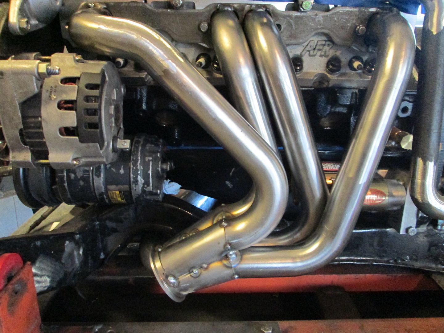
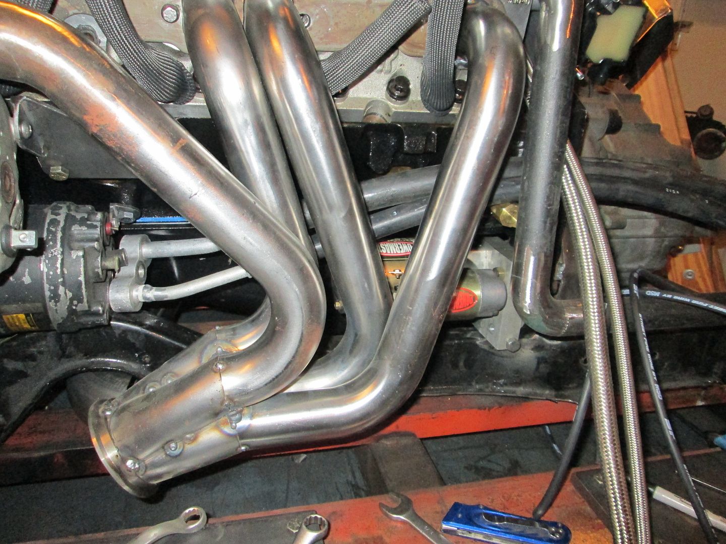
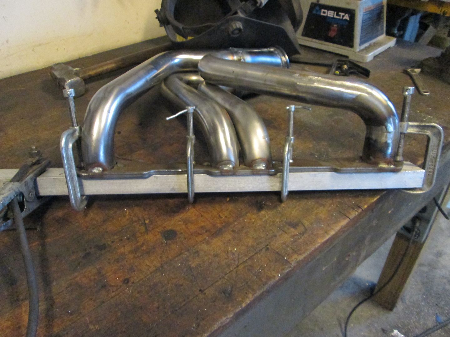
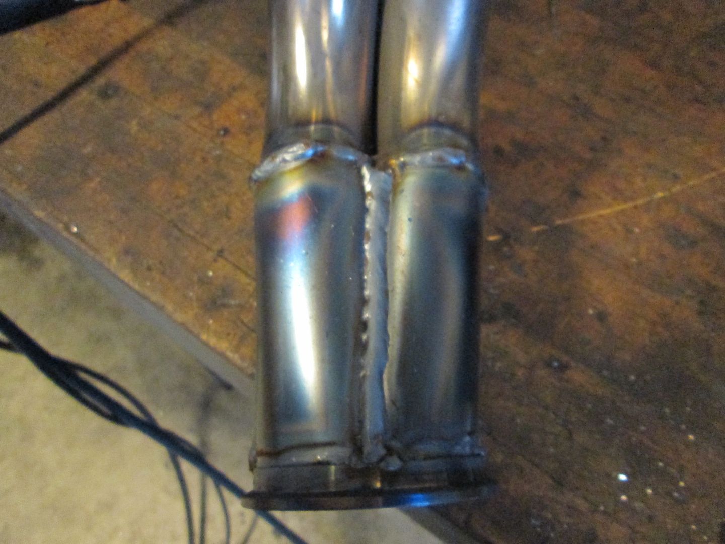
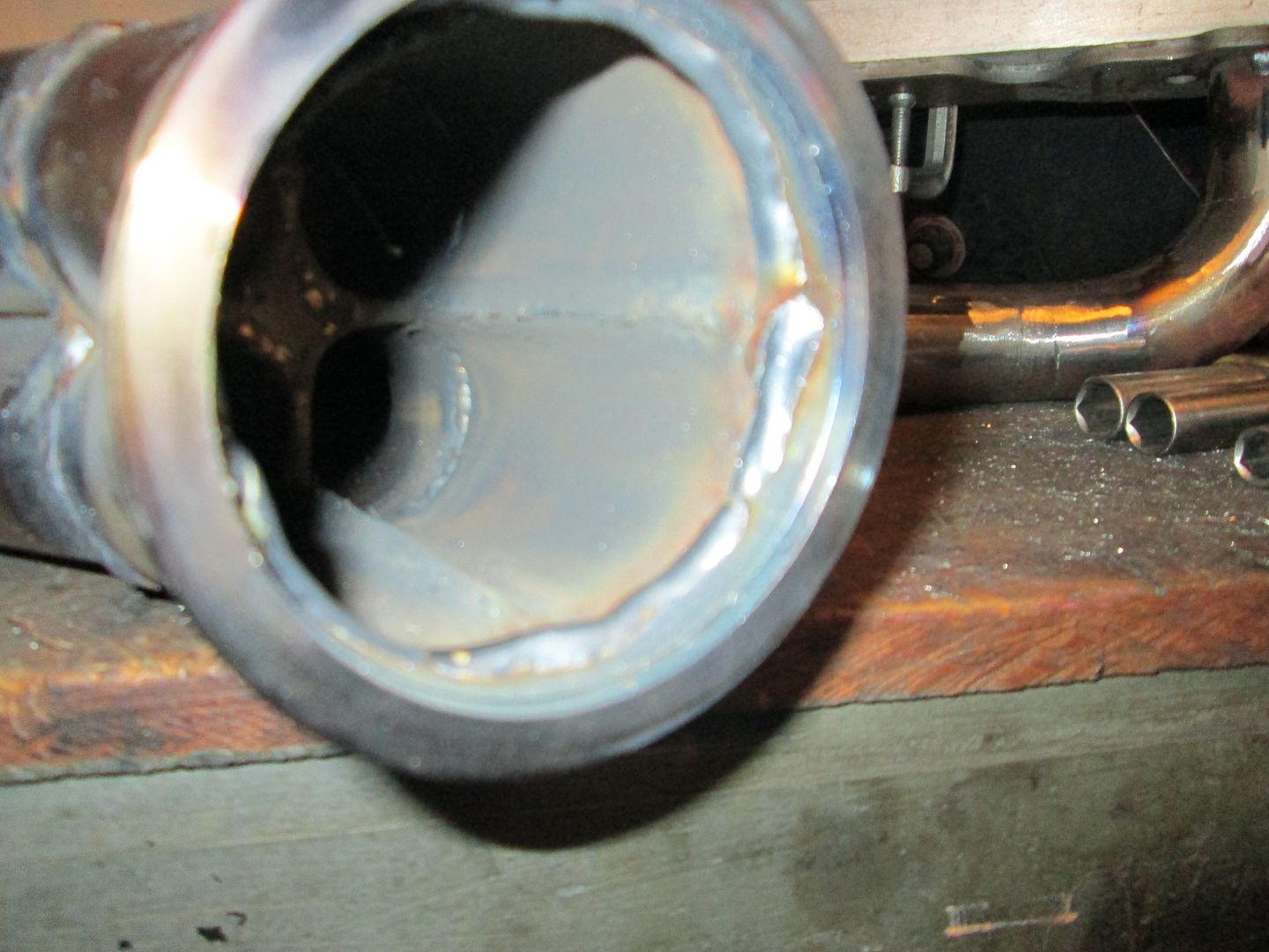
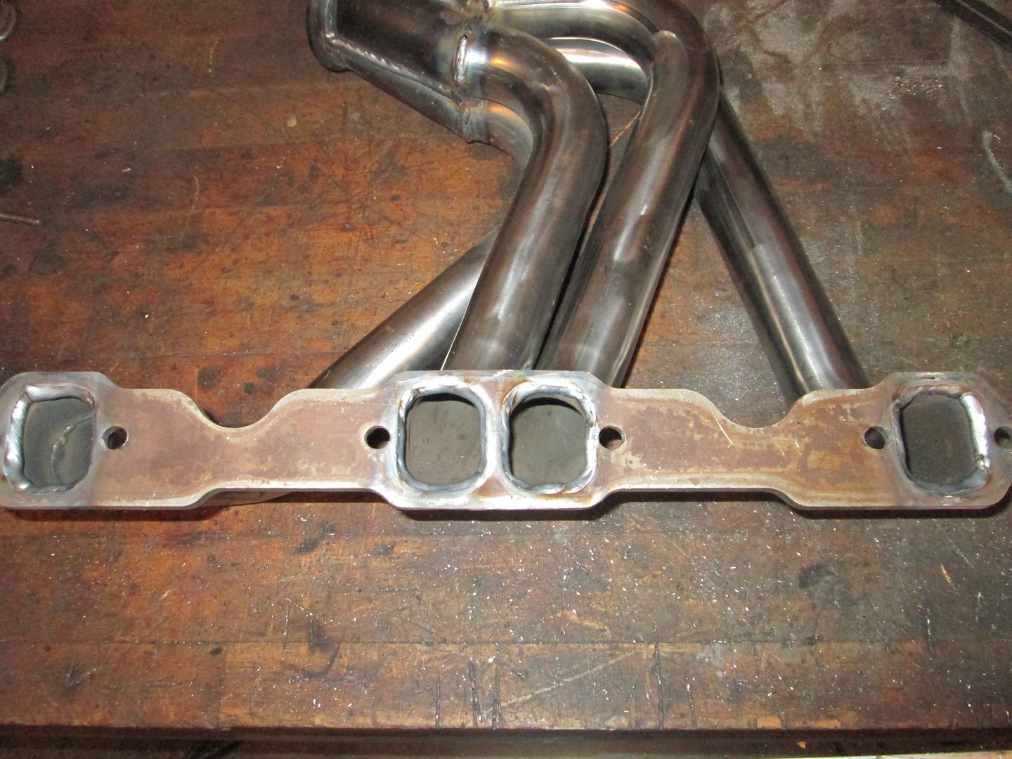
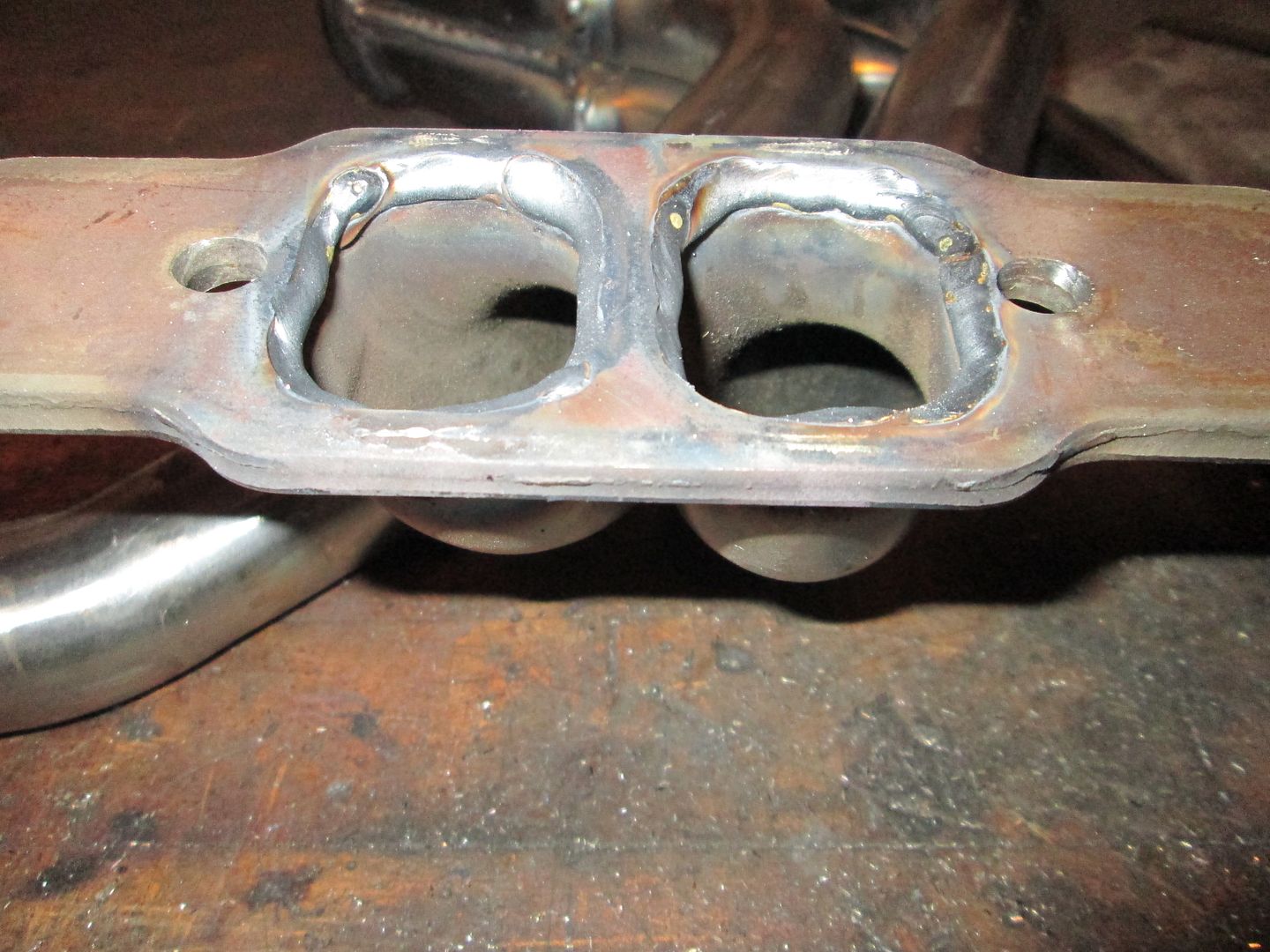
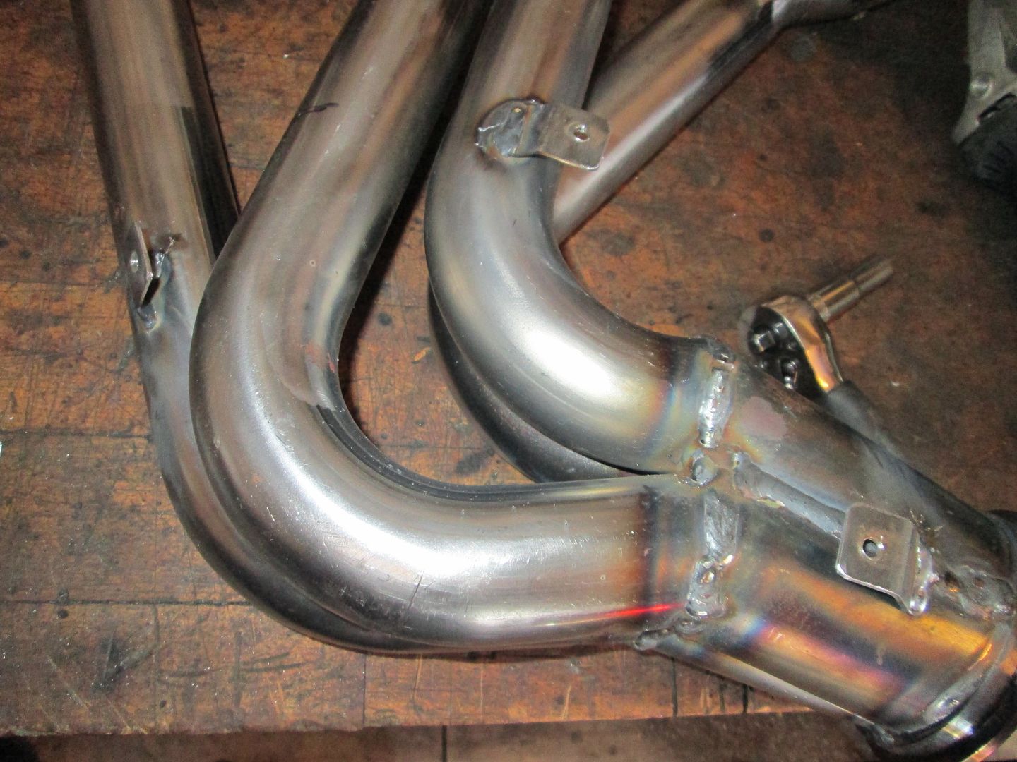
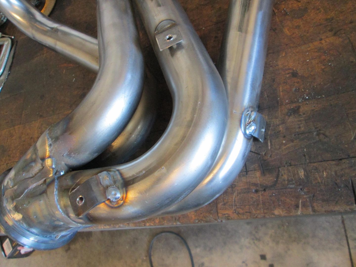
Also welded up the collectors and primaries on the headers:
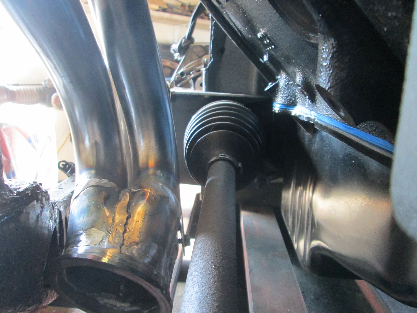
I should finished up the heat shields for the starter and tripod boot on Monday, then I will just be waiting for the O2 sensor bungs to arrive so I can add them and ship the headers off to be coated. Hopefully I will also start taking more stuff apart so I can start cleaning/painting all the parts I have fabbed for this swap.
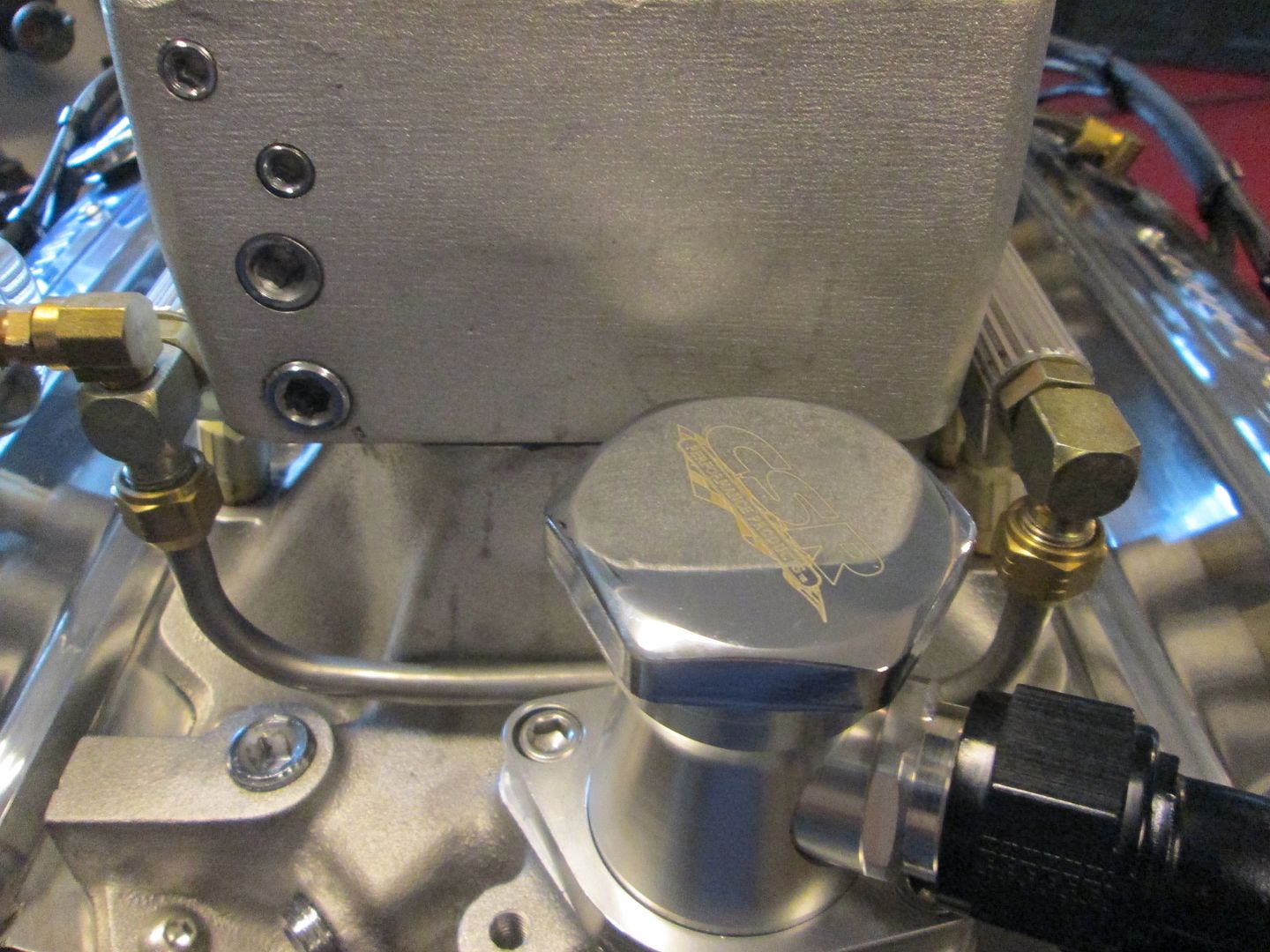
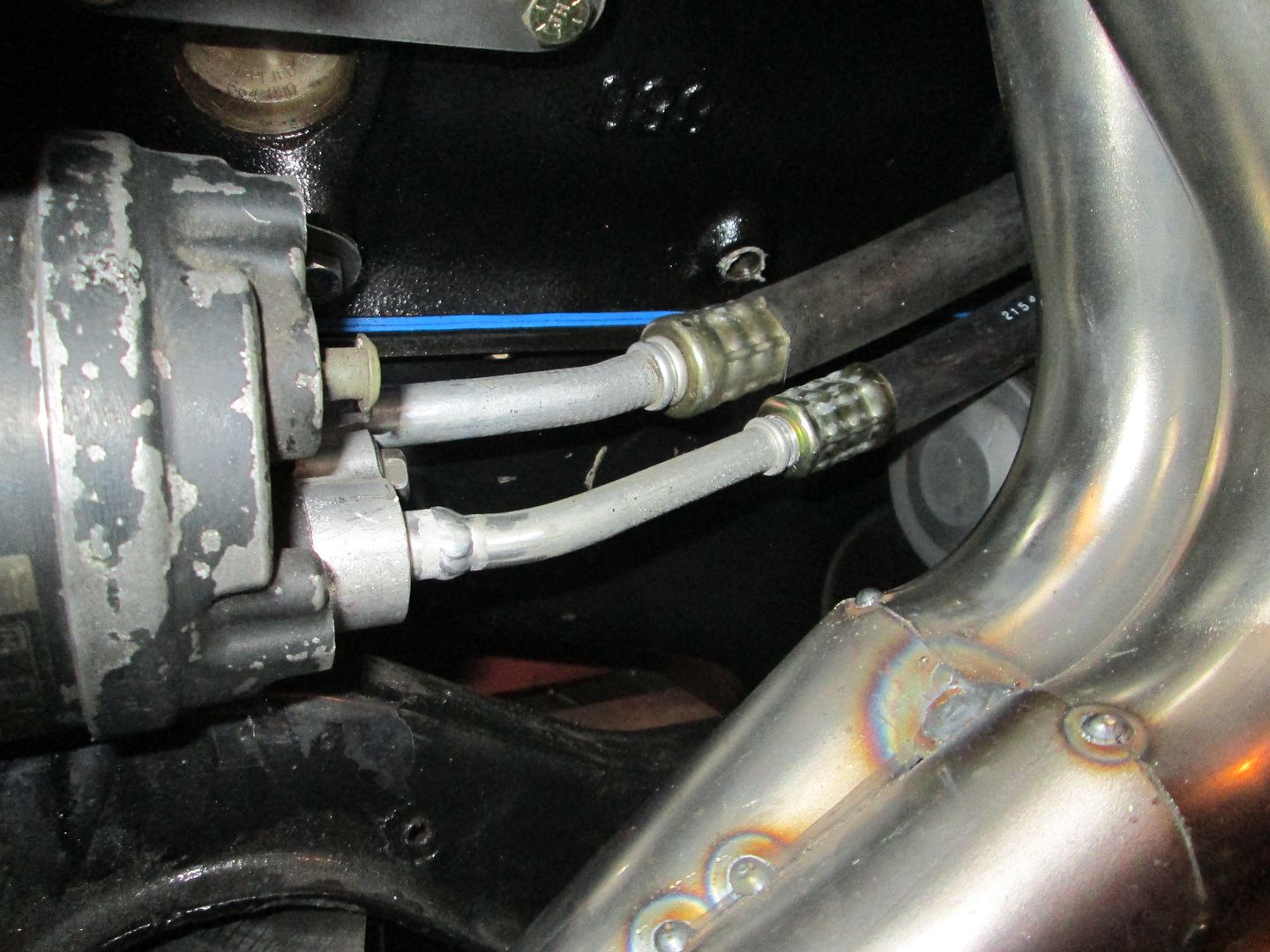
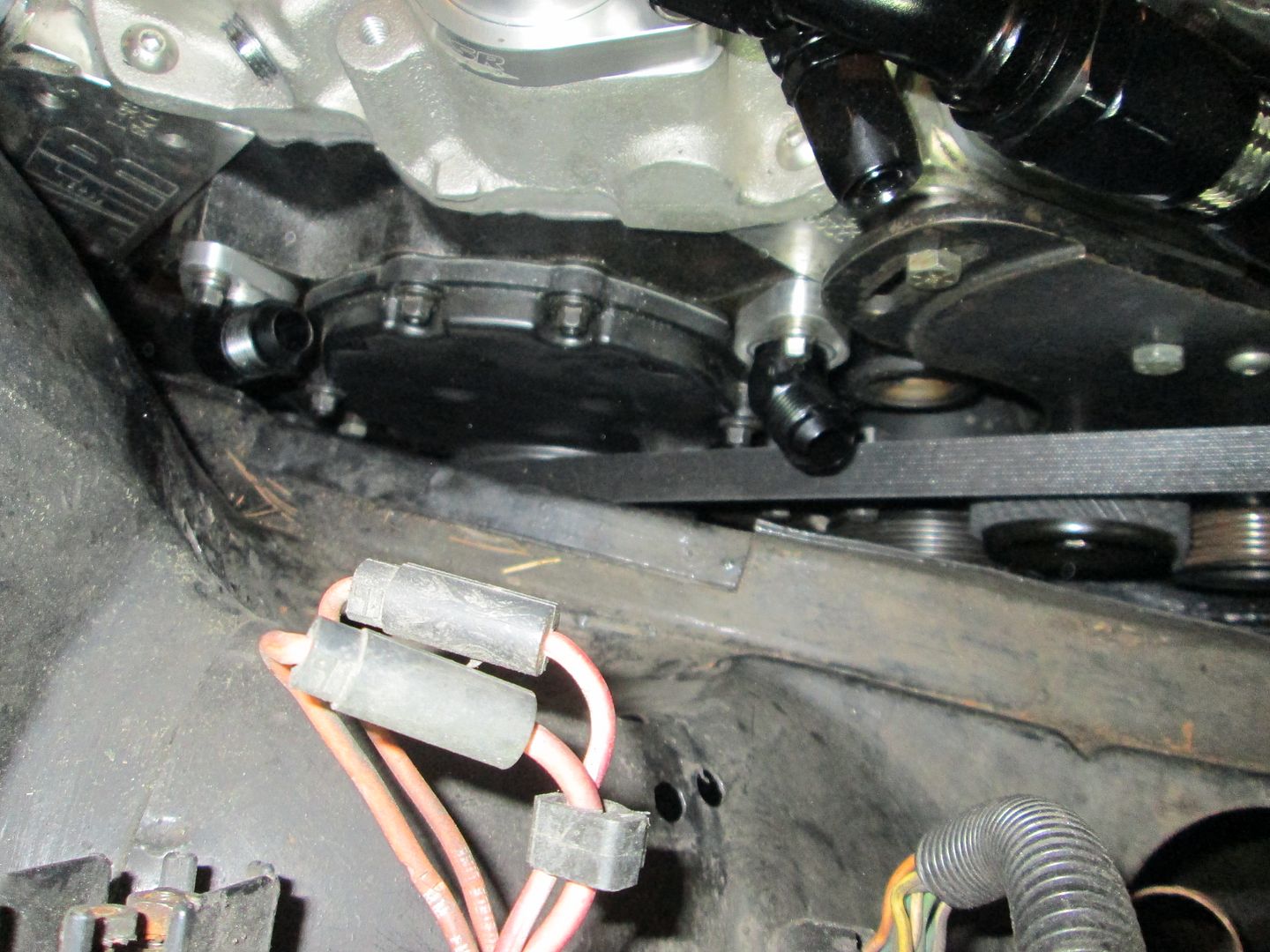
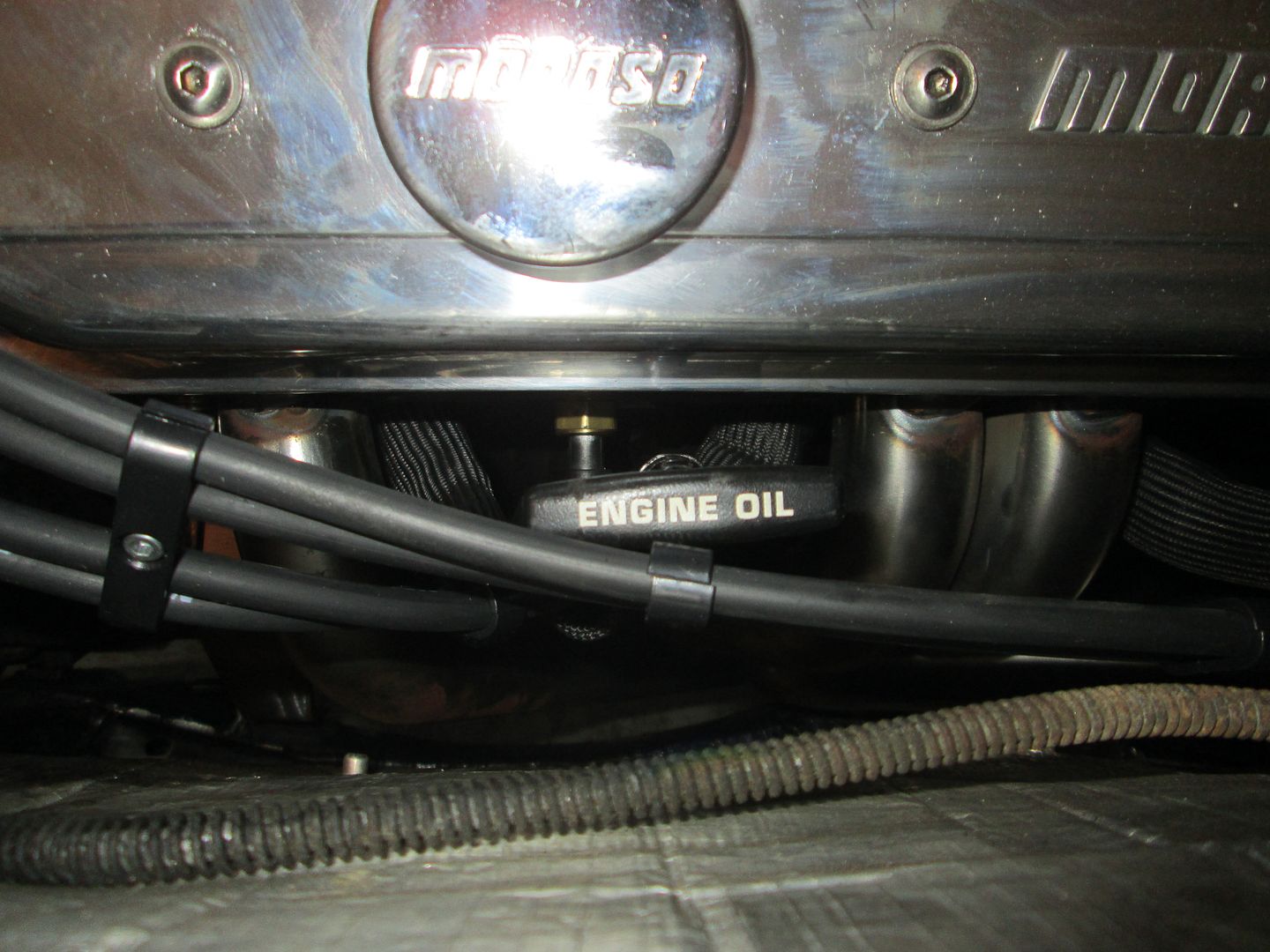
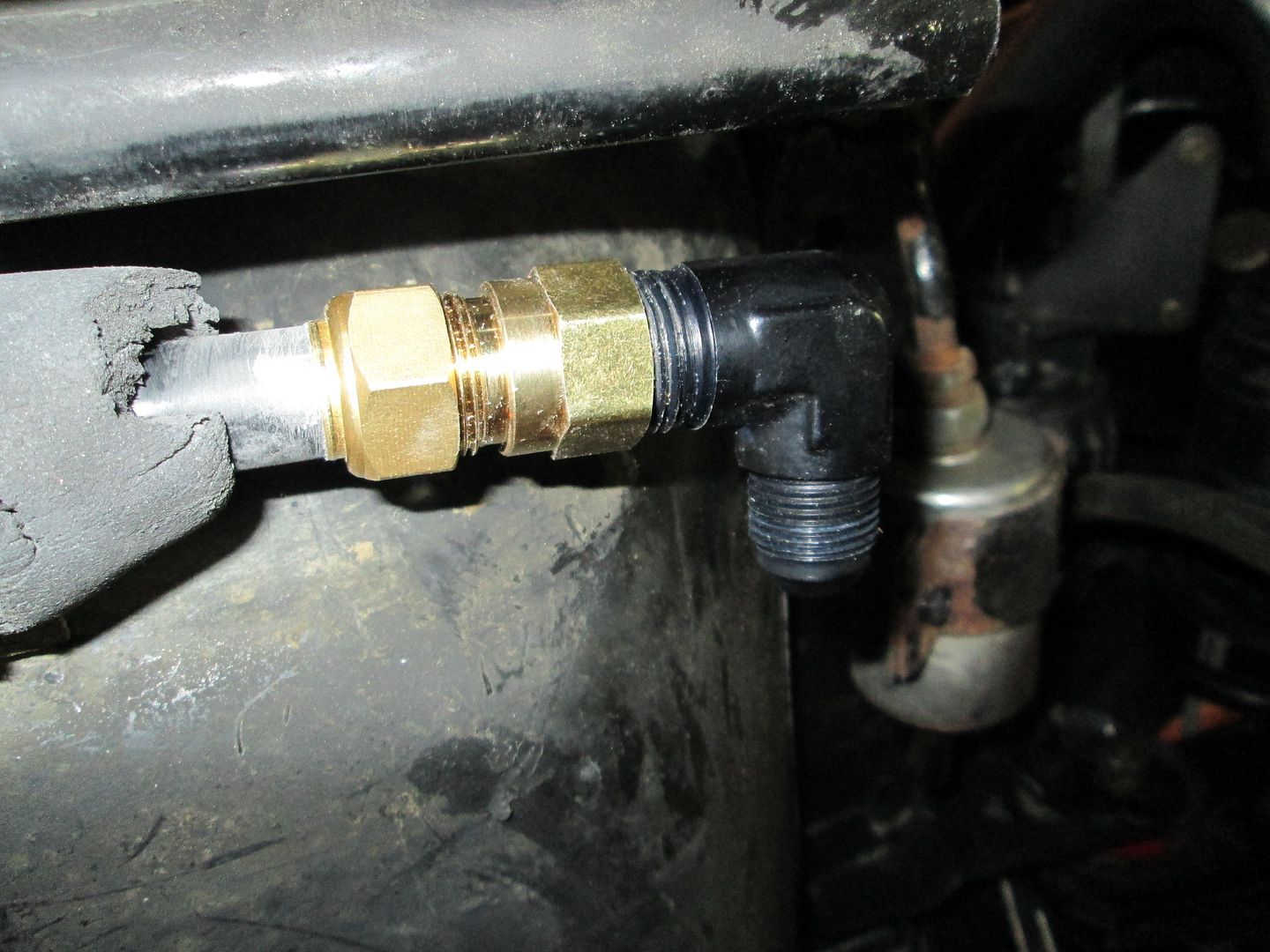
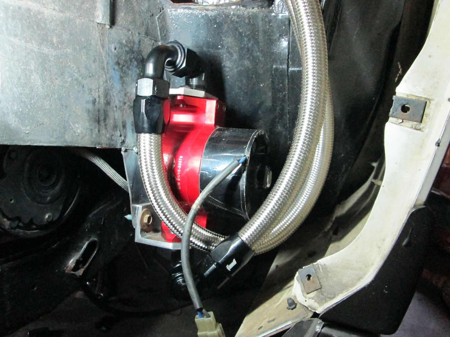
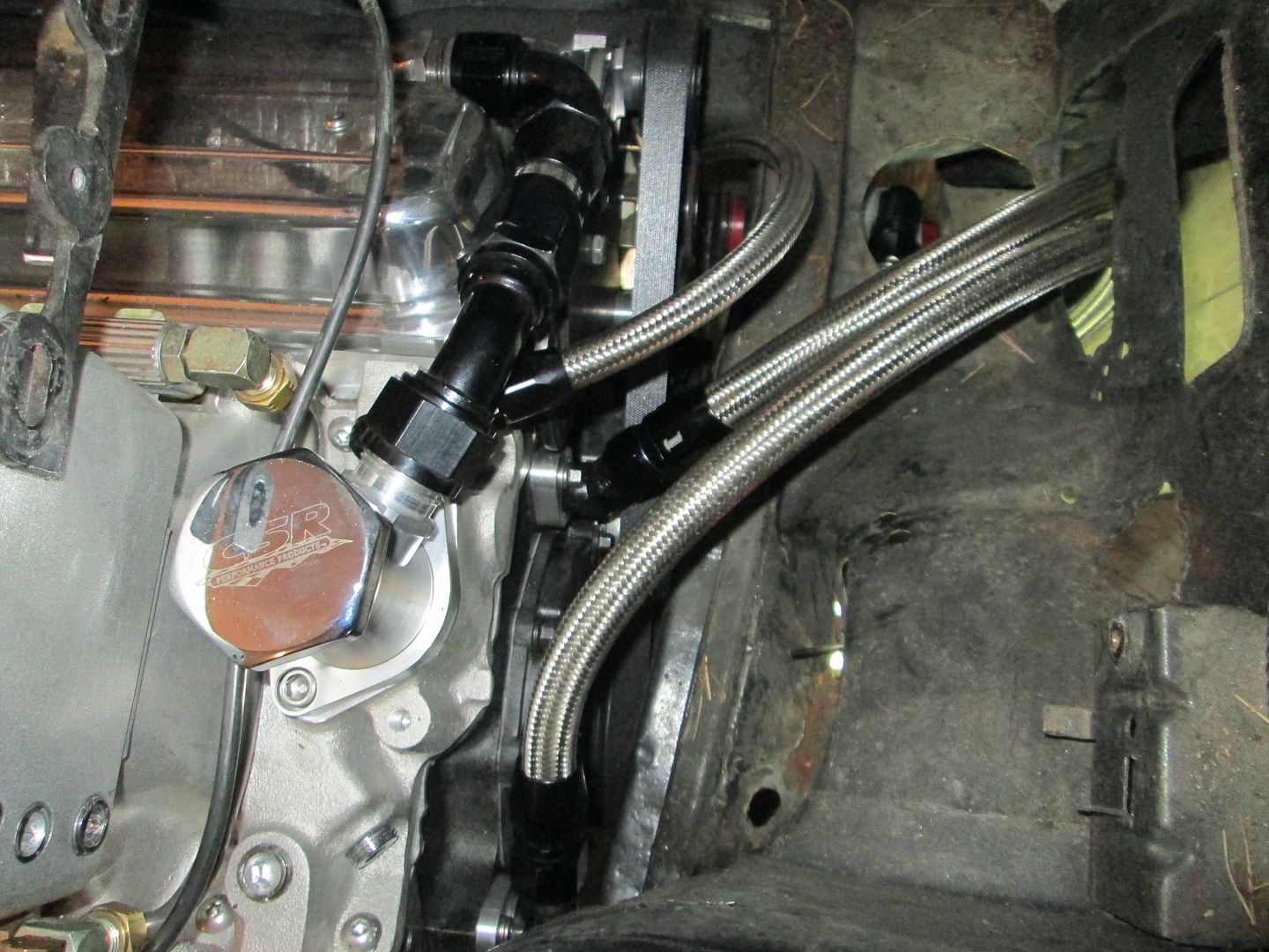
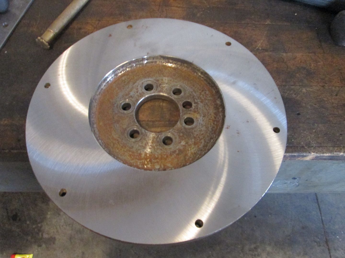
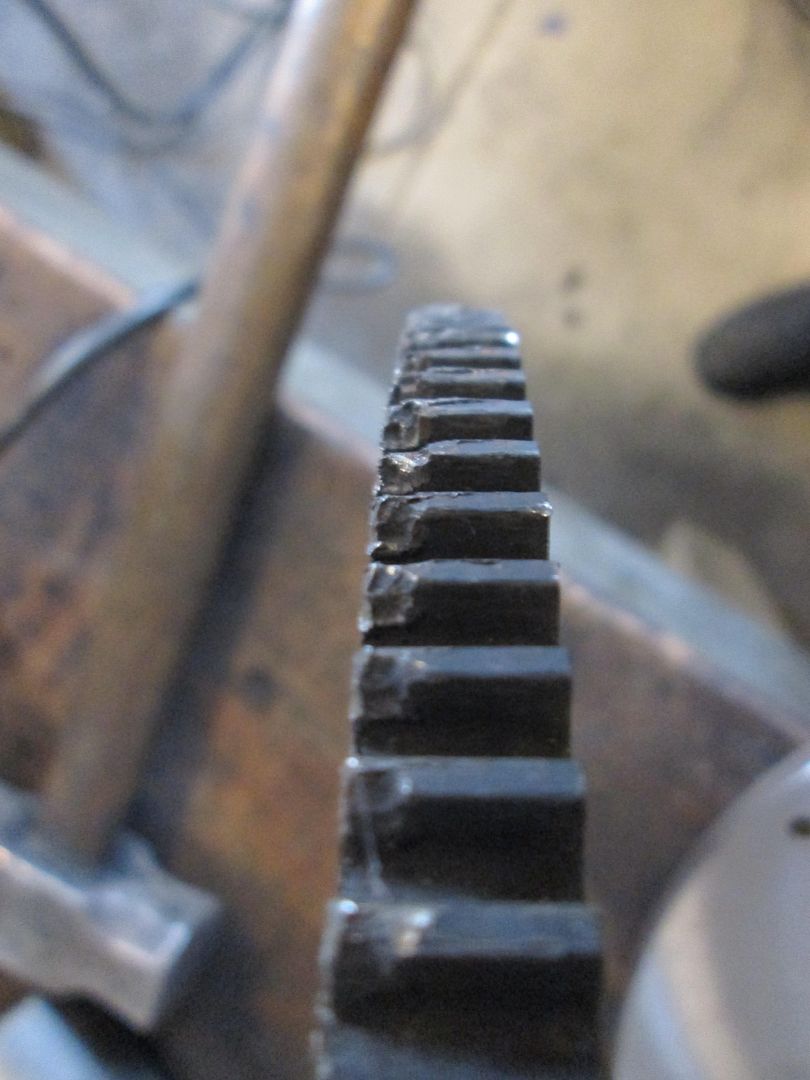
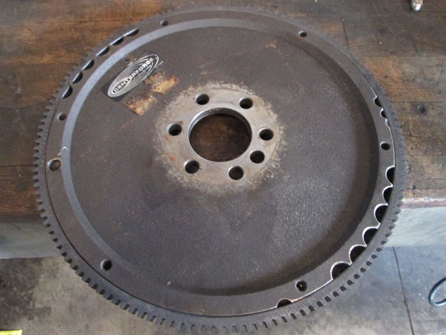
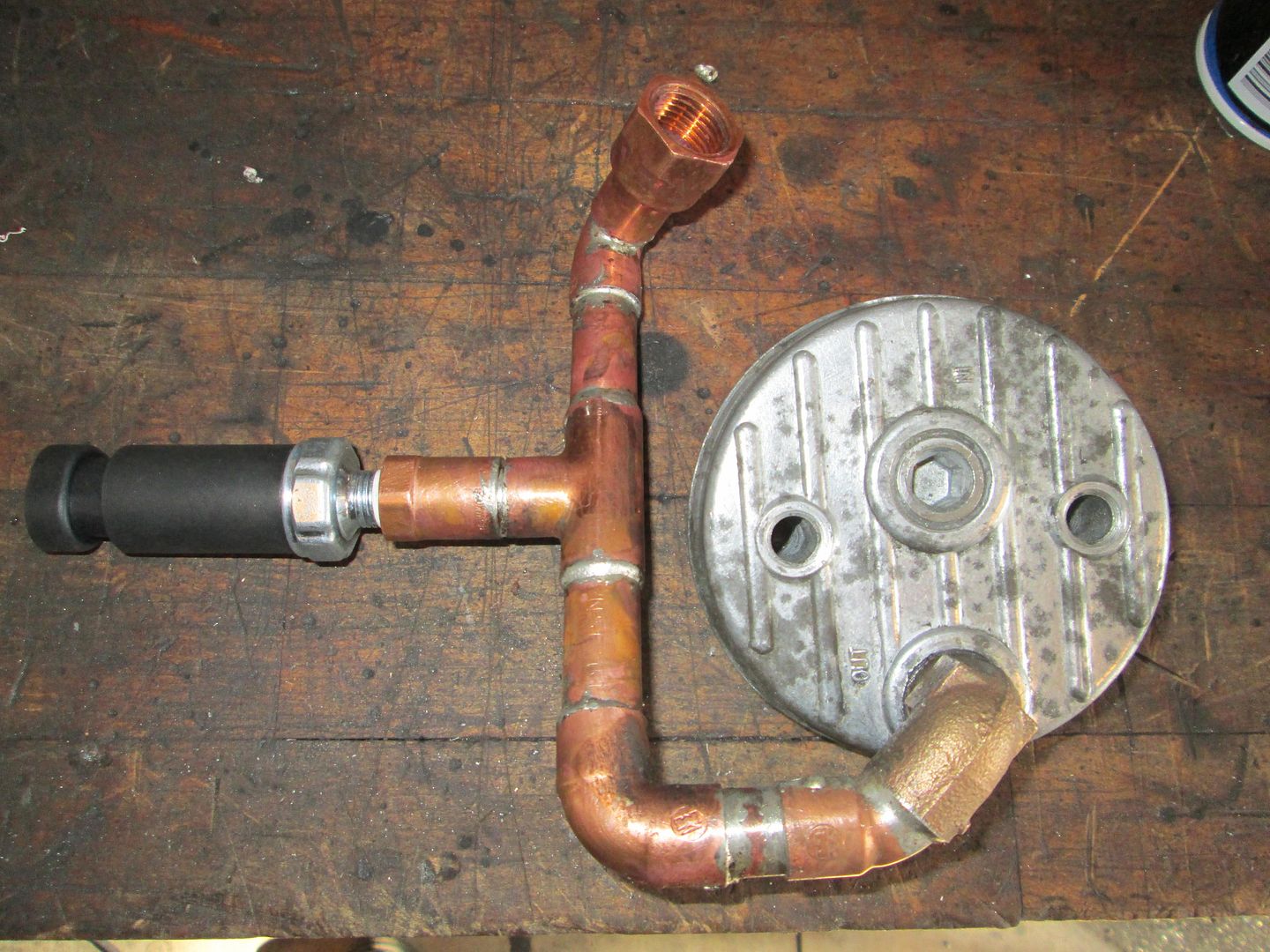
Also finished up the oil relocation plumbing. With the starter mod for the 142 tooth ring gear, I had to use some copper pipe at the connection to the blockoff plate, so I used it to get around the starter and provide a location for the oil pressure sensor. All assembled it looks like this:
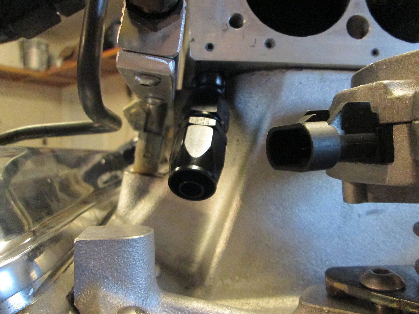
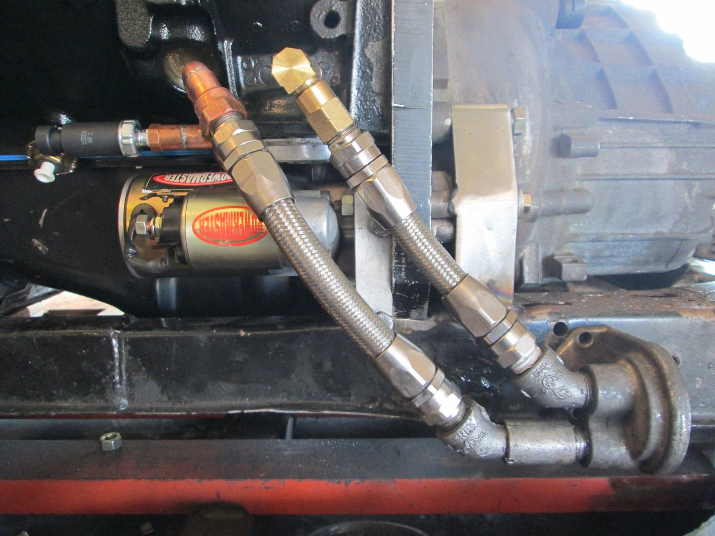
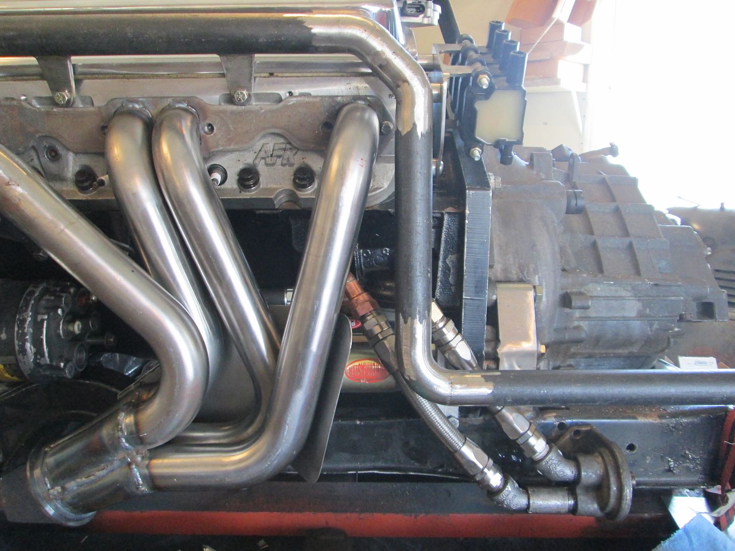
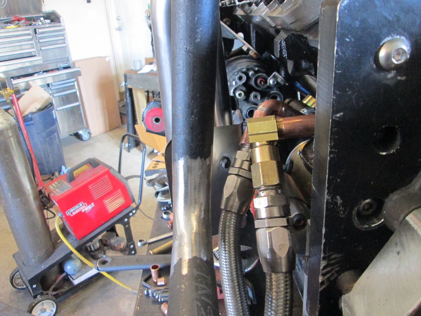
Installed with the braided stainless hoses, it looks like this:


 Topic Closed