It's actually going great! FieroGuru has sent me a few things in PM to see what I thought about them. He also enlarged the oil return hole on the side of the block, which is great, and makes me feel a bit more comfortable since the engine builder put in a high flow oil pump, so I won't be punishing the pump with (as much?) backpressure.
And of course FieroGuru has his own stuff to do, he was doing some work on one of his brake projects, and he had gone to an event to put his car through the paces. He's been outstanding about sending me updates!
Right now I think he's also waiting for my clutch to show up. I had a 6-puck sprung hub ceramic clutch from Clutchnet. He didn't know how much material was left on the face (compared to a new one), and Oleg didn't get back to me on that question, so I ordered a new one anyway, figure I'll keep my old one as an emergency backup.
Yeah, progress has been slow the last few weeks due to LS Fest and spending time on my car, working on quite a few brake kit orders, and last week we had plant dinners on all shifts on 2 days (4 crew plant) so I was working some very strange hours... However Vince's engine did get some love this weekend.
I had already installed the timing cover for the last time, made a timing notch for TDC (just to assist with positioning the cam sensor), and installed the oil pan with a new gasket:
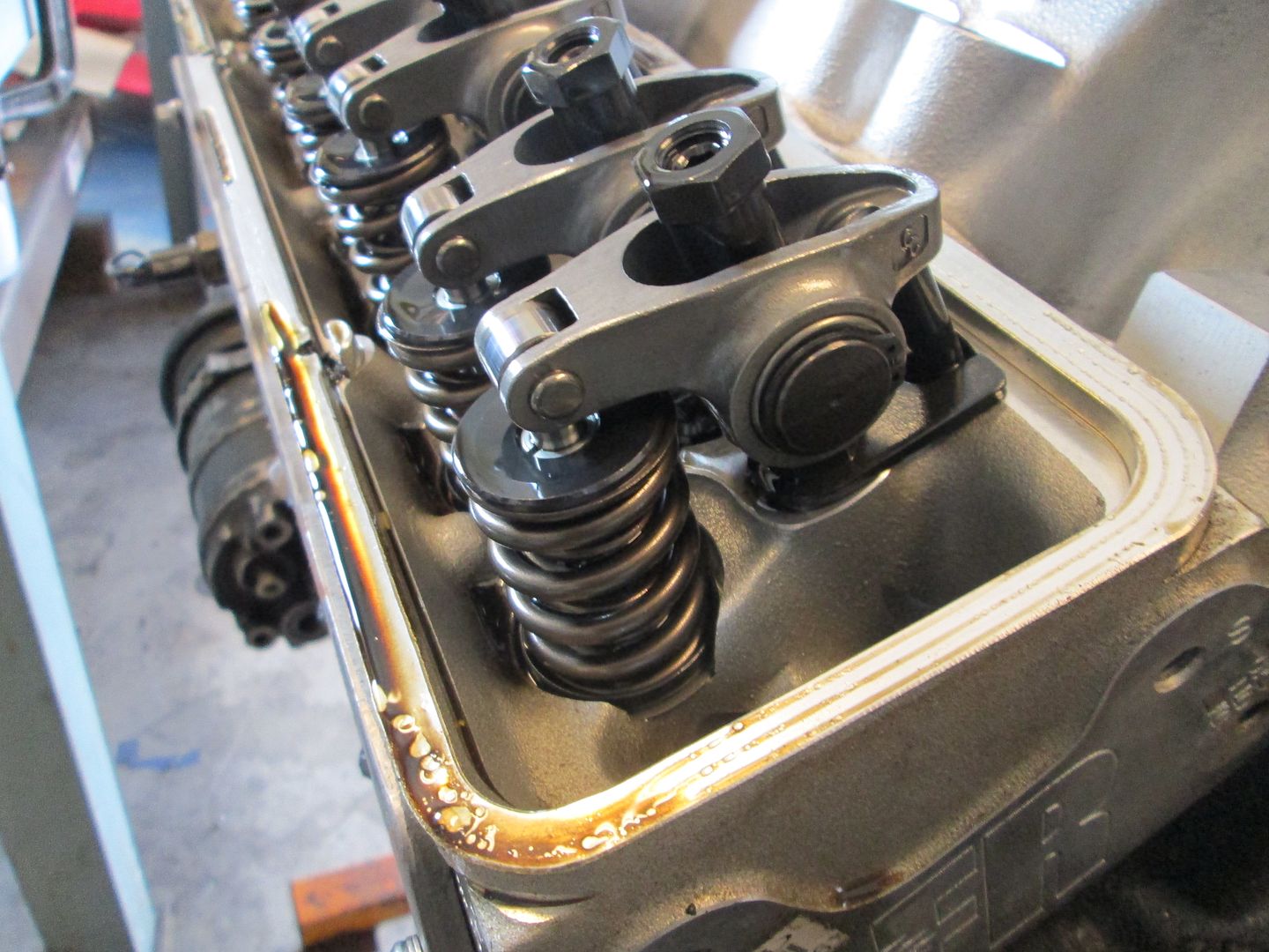
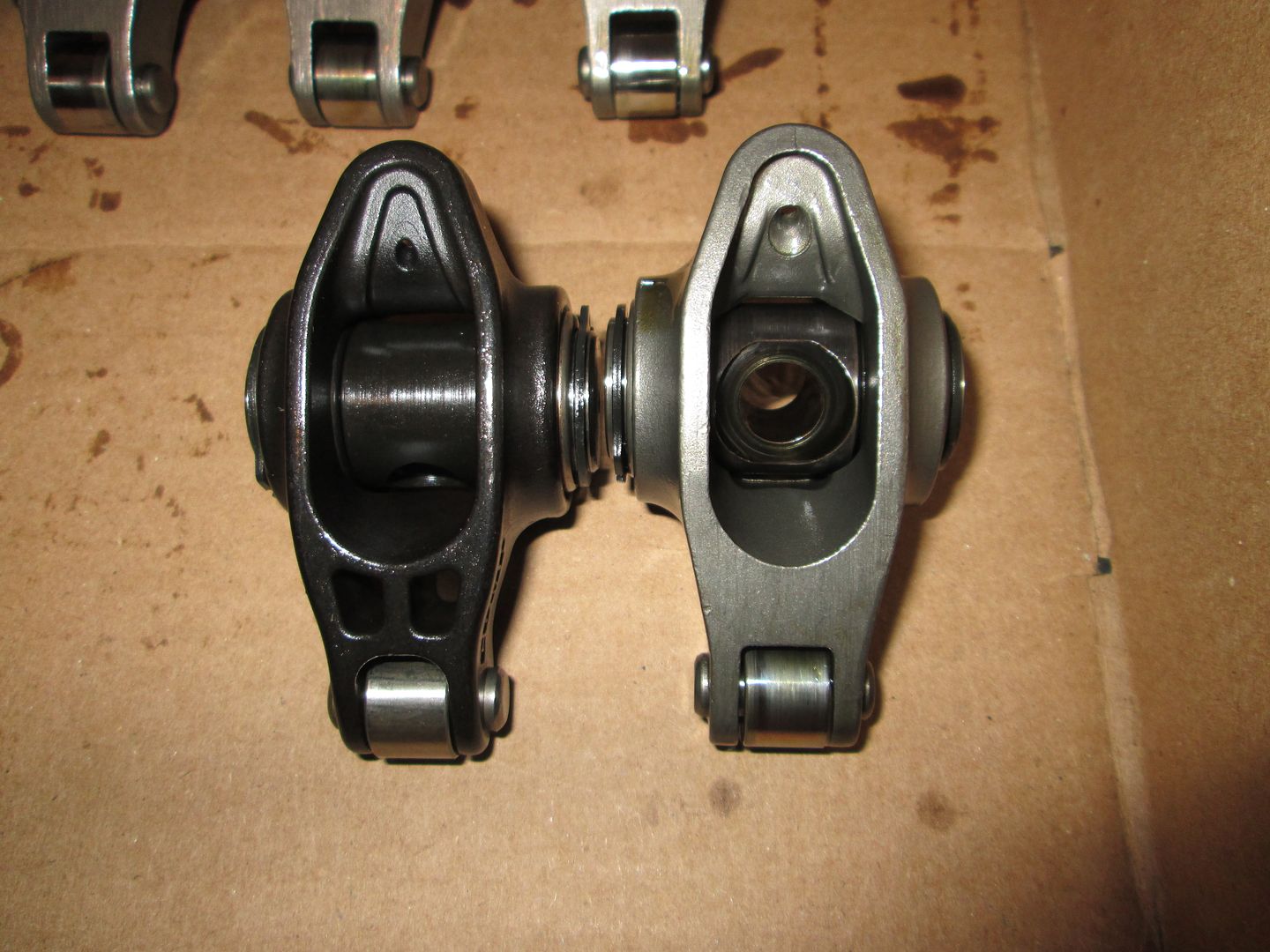
Next I wanted to button up the valve covers, so I swapped out the roller tipped 1.52 ratio rockers with the 1.6 roller tipped rockers. With these, his roller camshaft specs are: 230/236 .576"/.570" with a 113 lobe separation (Comp Cams 280XFI HR13 part # 07-467-8). With his AFR heads flowing more at .600 than .550, he should see some additional peak HP and possibly push this thing over 400 wph (371 whp was the previous tune). Here are the 1.5 roller rockers:
Comparison pic (1.6 on the left):
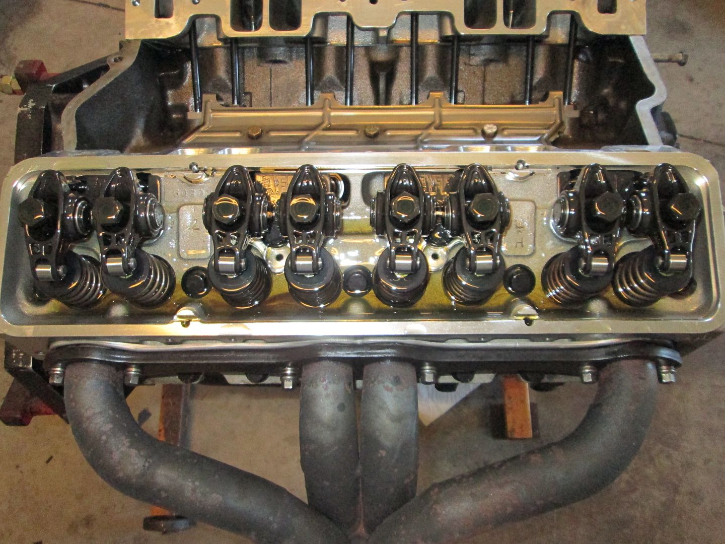
Installed:
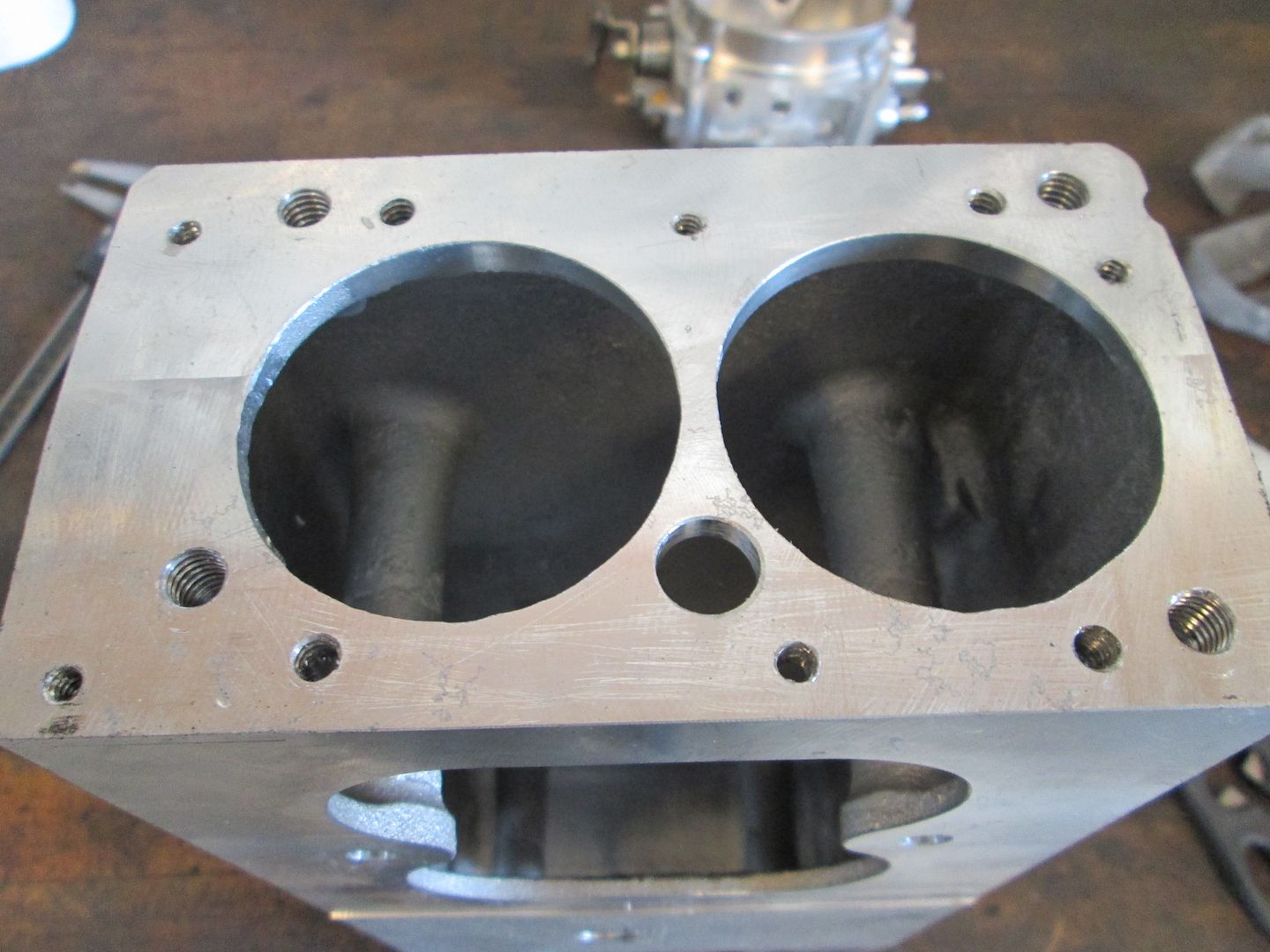
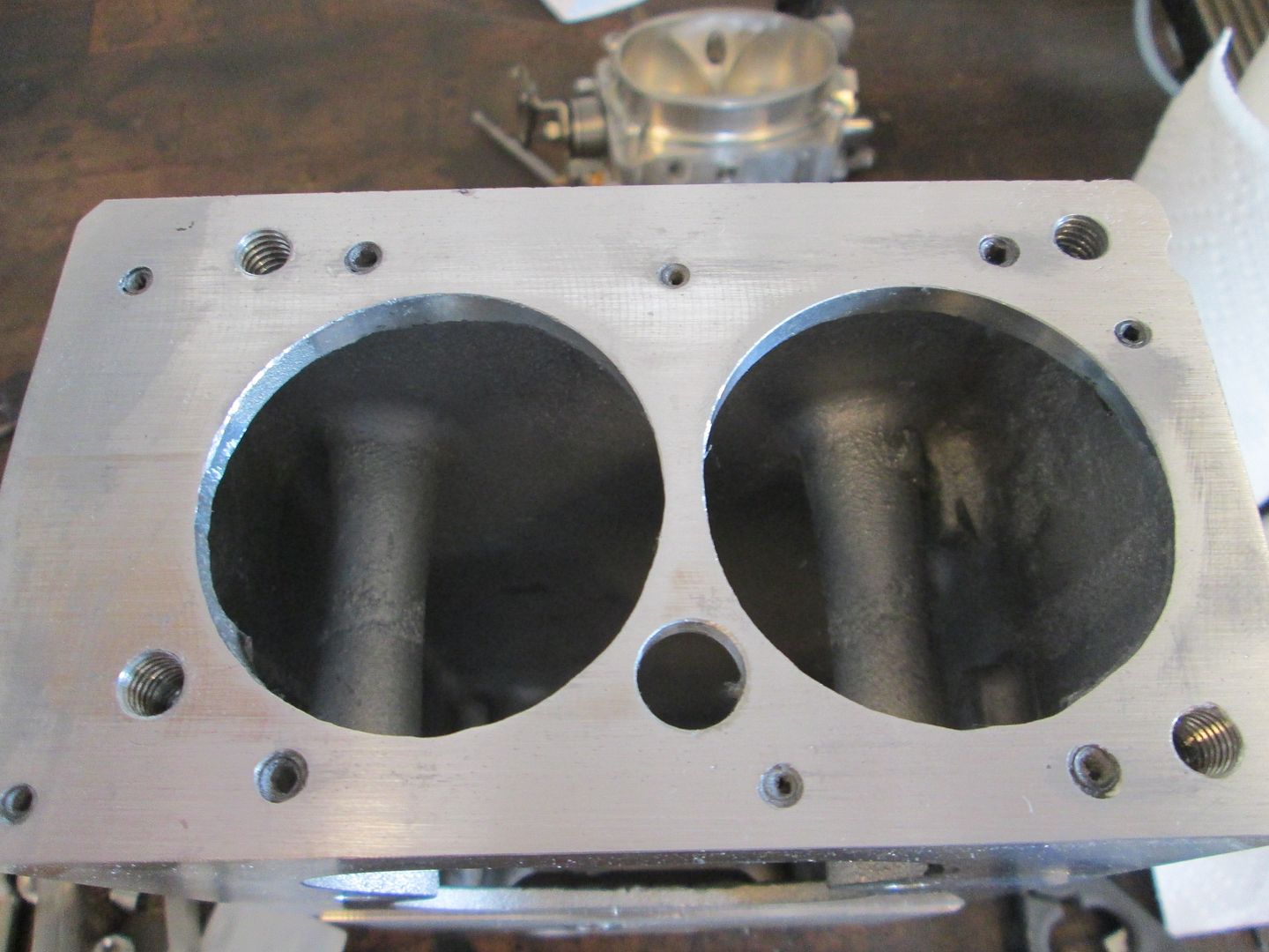
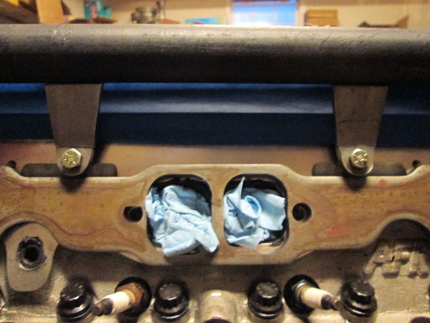
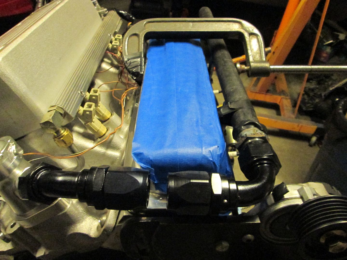
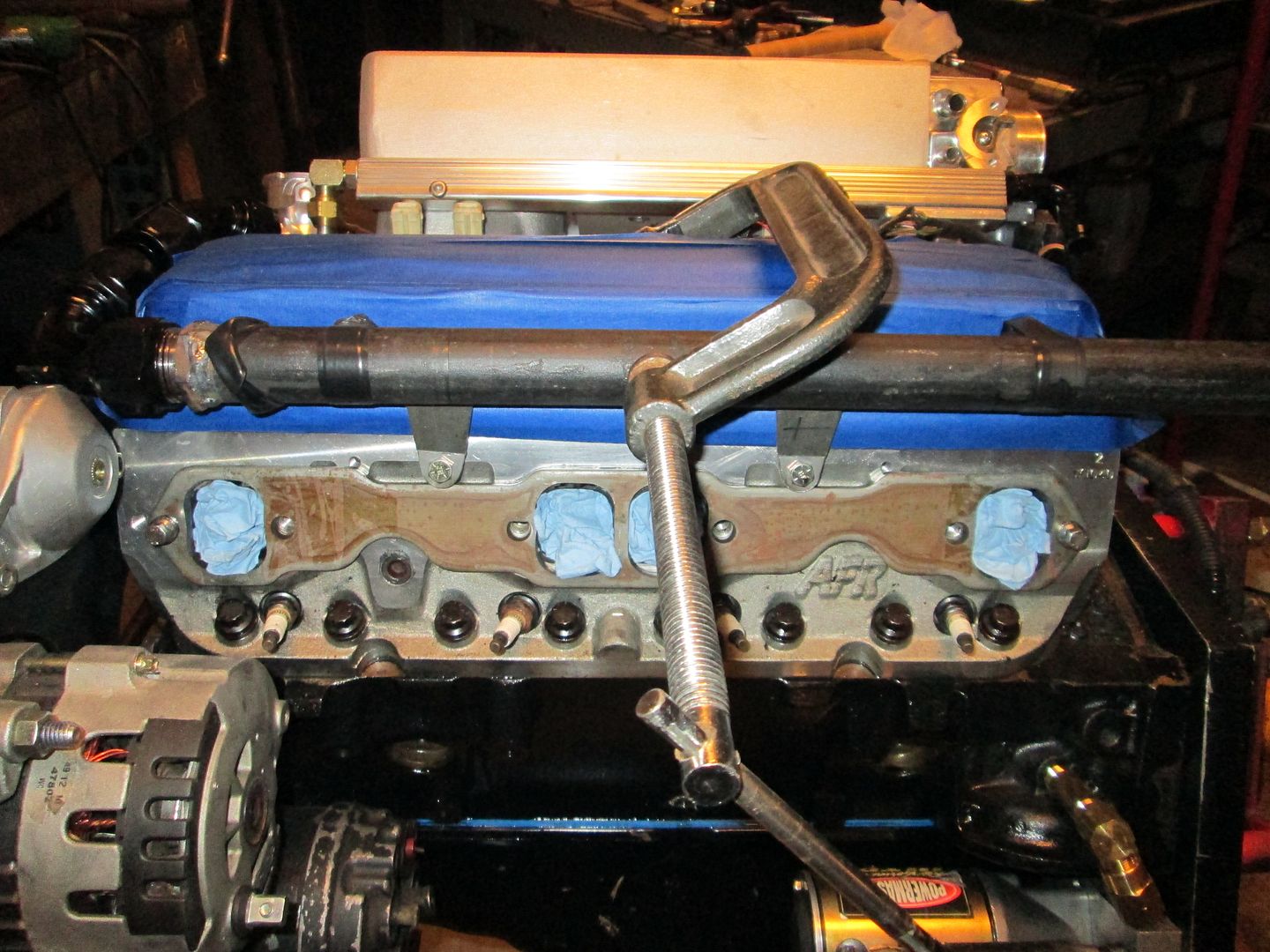
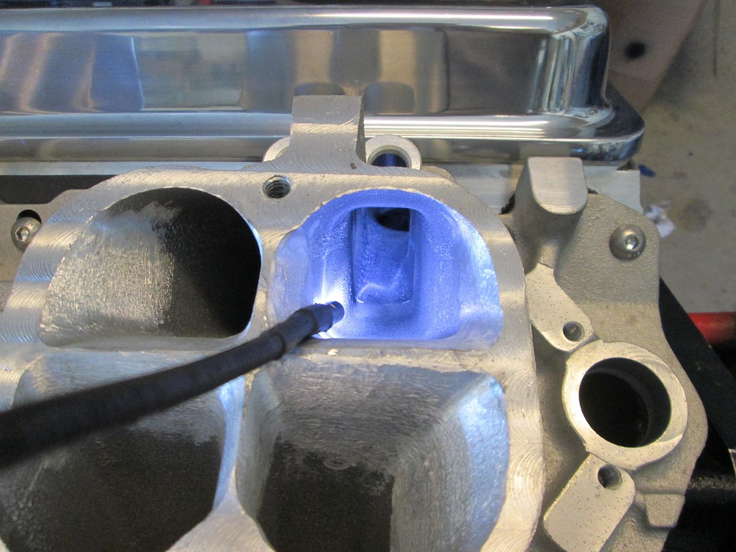
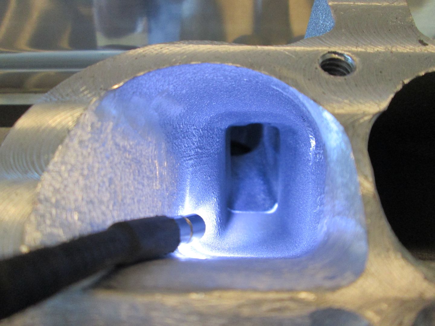
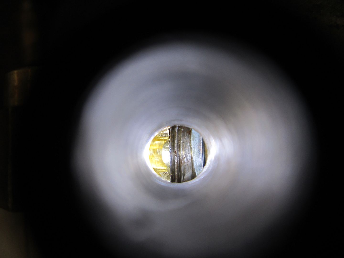
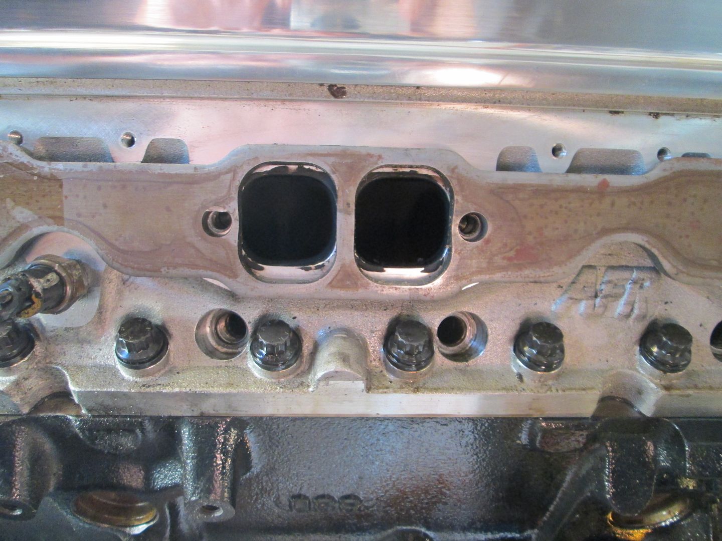
The bolts for the valve covers were about 1/4" too long to tighten the valve covers, so I shortened the 8 bolts, dumped a quart of oil over each bank and installed the valve covers. Next was to install the lower intake, I dumped 2 quarts of oil over the lifters, installed the intake gaskets, installed the intake, lined up the intake runners to the head ports (with a tunnel ram you can "see" the alignment), then torqued it down. All the ports looked like these two with just a slight portion of the lower corners of the head protruding past the ports on the HSR.
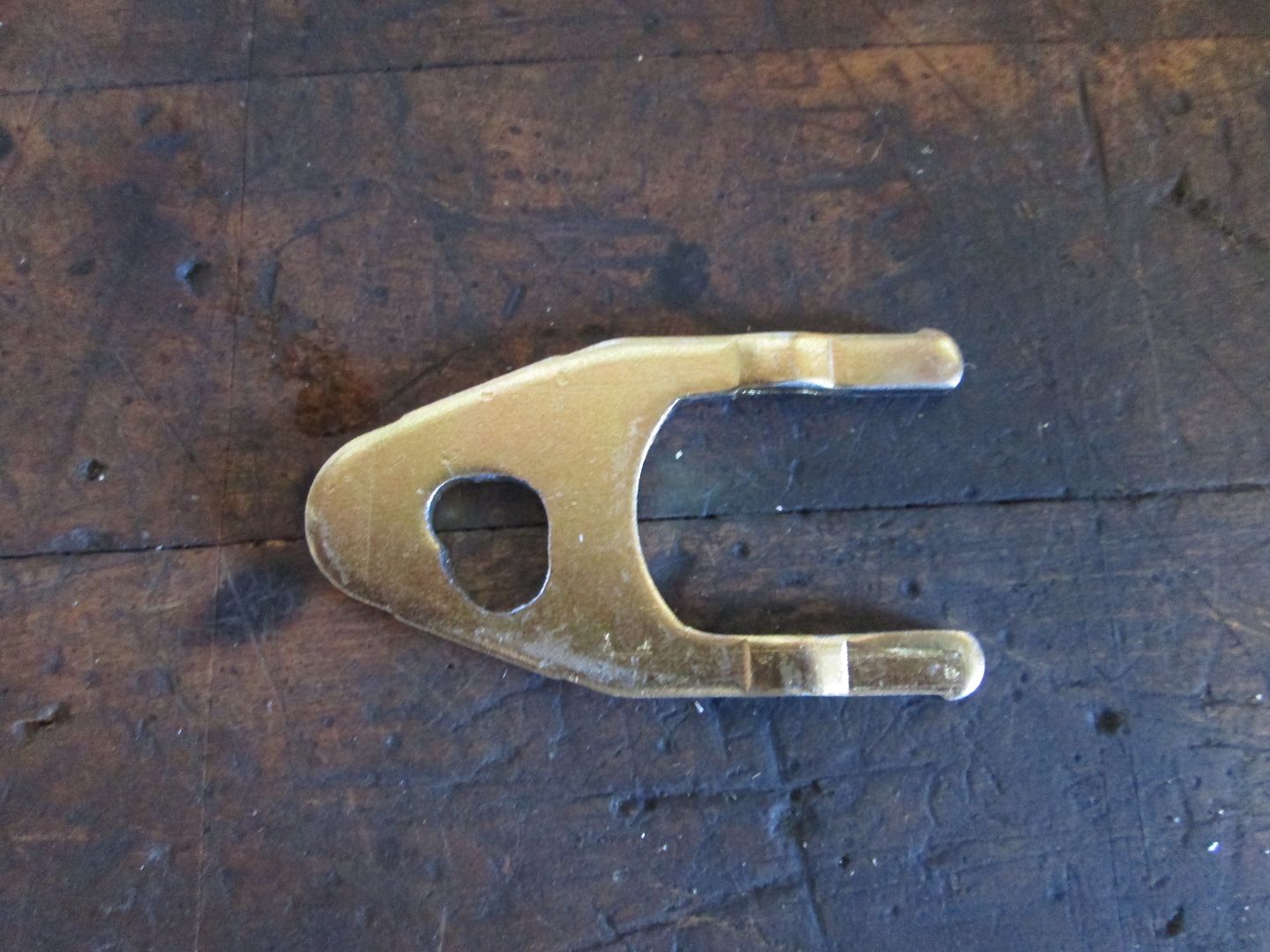
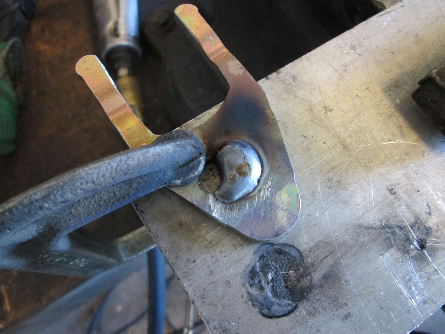
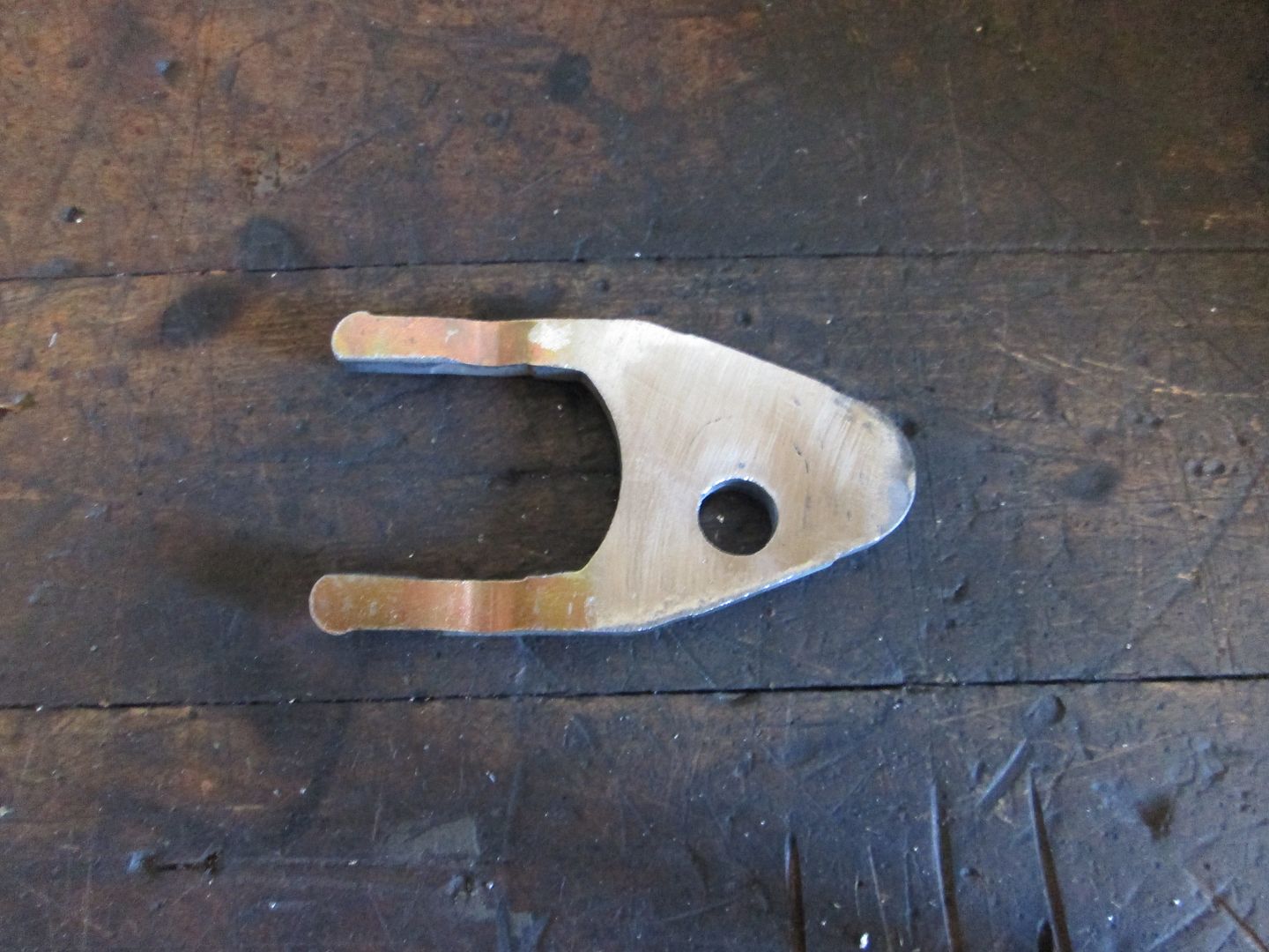
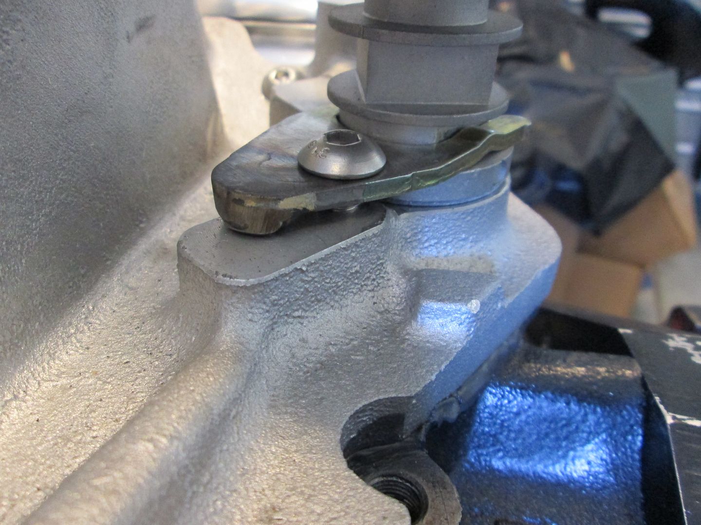
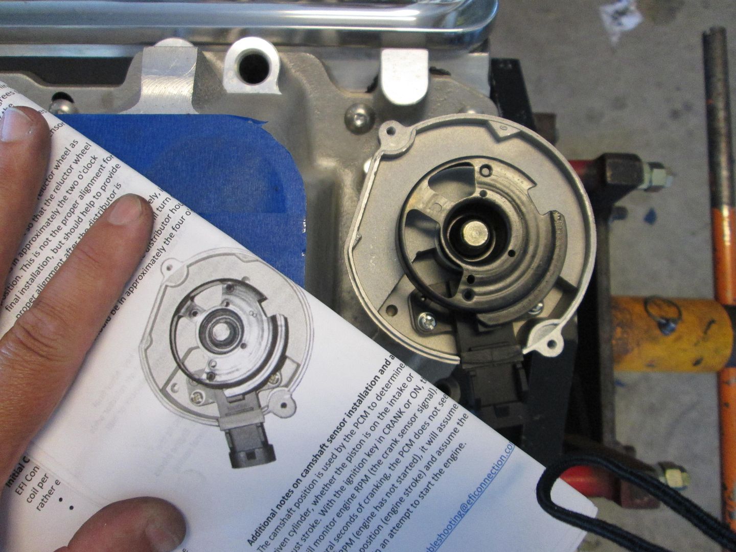
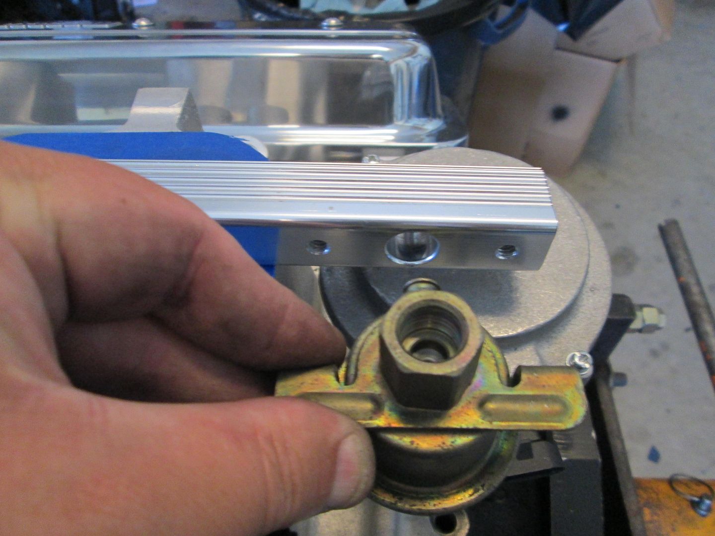
All of this work to button up the engine was to finalize the cam sensor location in the distributor housing. It took some trial and error to get the sensor lined up with the connector pointing the direction I wanted it, but eventually got there. Then the hold down clamp had to be slotted to the right position, then the original hole welded up and smoothed, the bolt hole redrilled, and a pivot stand welded to the hold down... Now the cam sensor is aligned per the EFI Connection instructions!
Hold down slotted:
Filled:
Smoothed and redrilled:
Installed:
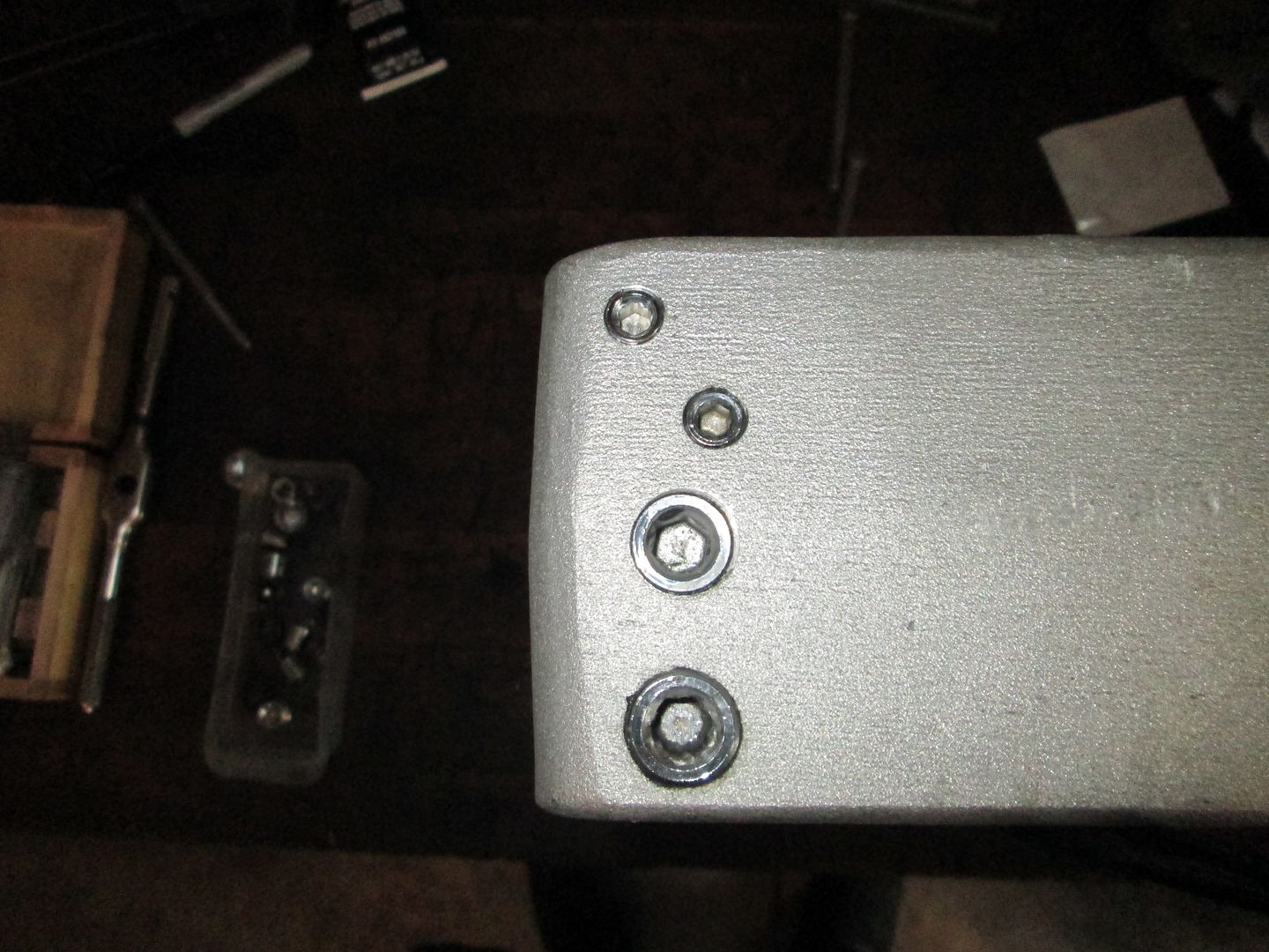
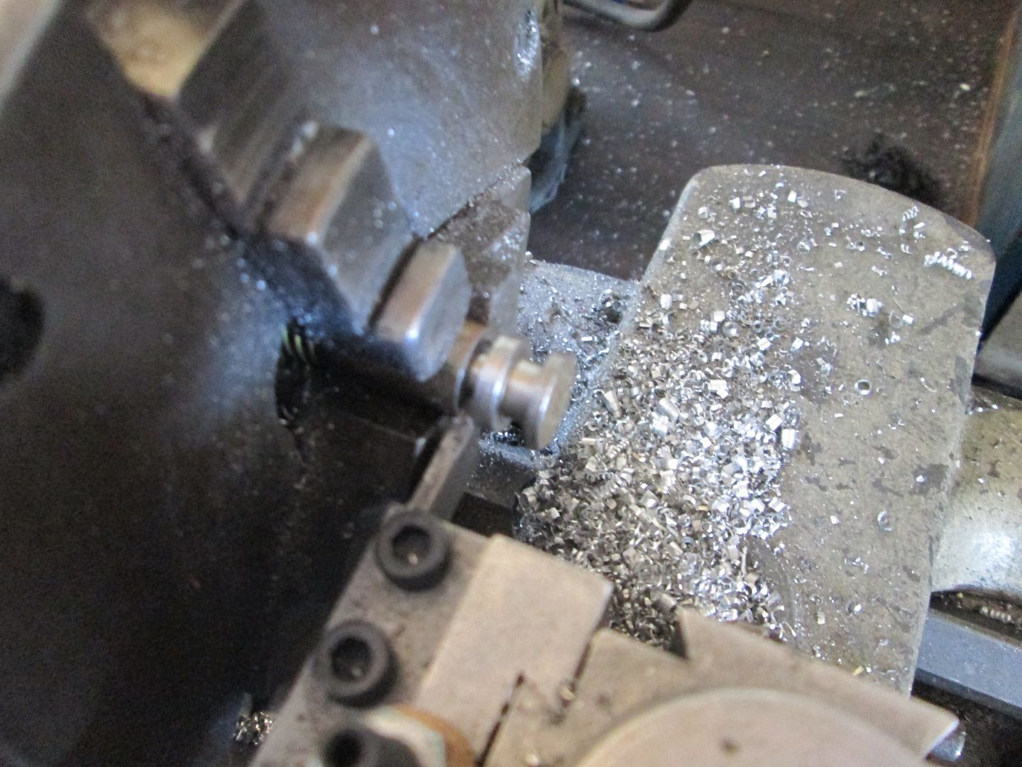
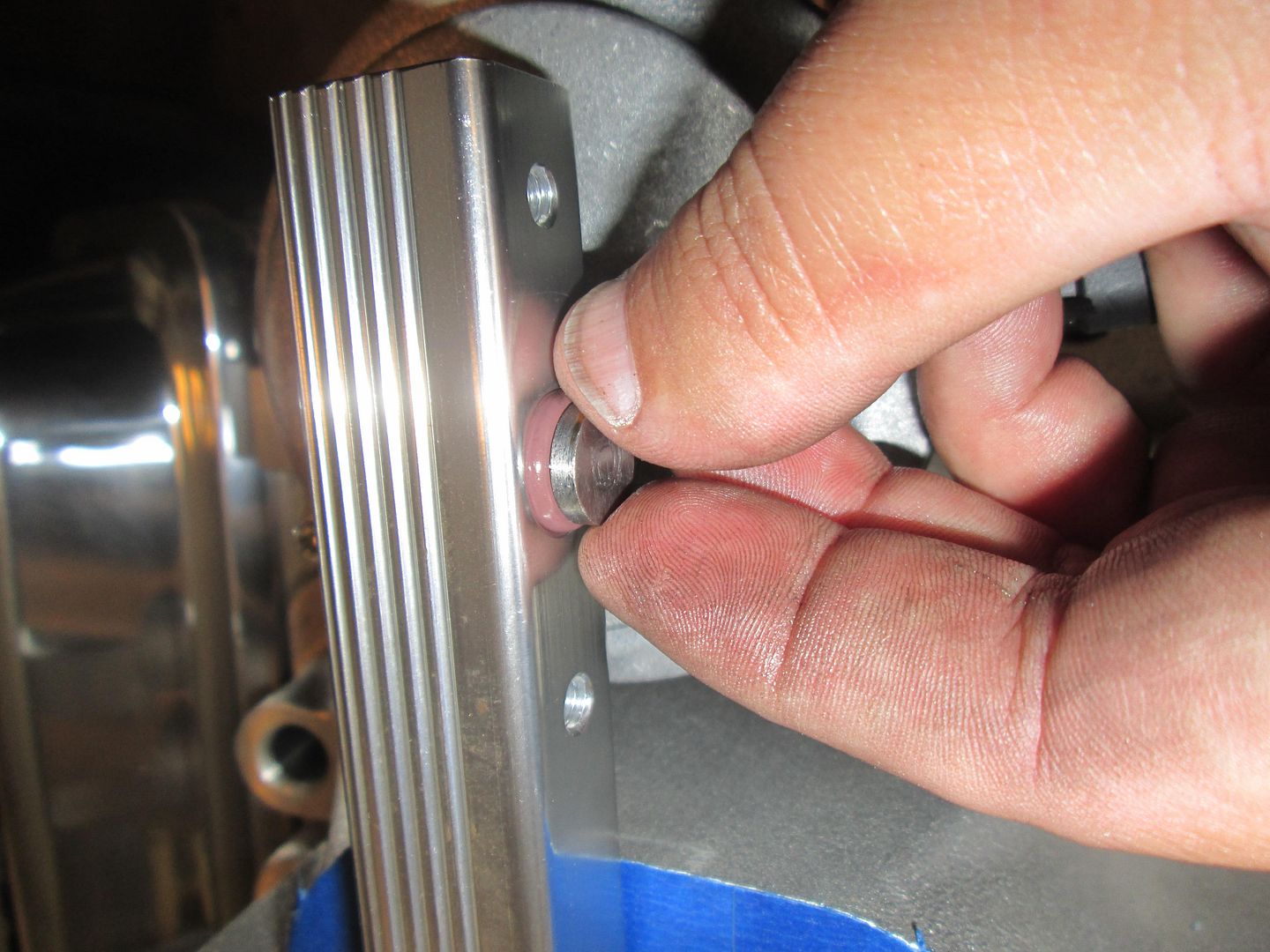
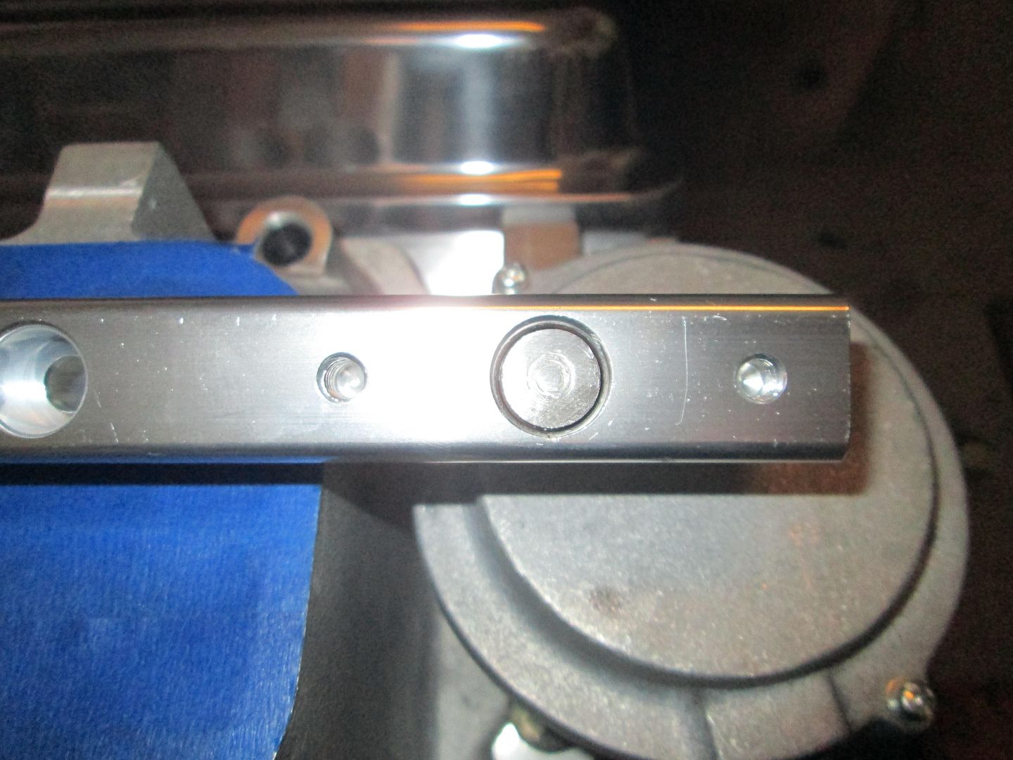
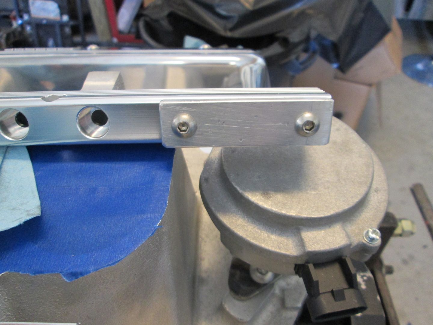
Next I set to work on the fuel rails. They are setup for a rail mounted regulator and I am converting them to returnless, so I needed to fill the regulator port. I turned a plug with the same o-ring groove as the regulator, fabbed up an aluminum bar to span the plug and keep it secure, then trimmed the stainless steel button heads to the right length.
Bypass regulator and open port:
Turning a plug with o-ring groove:
Installed:
Capped:
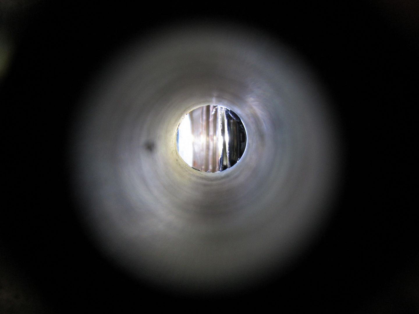
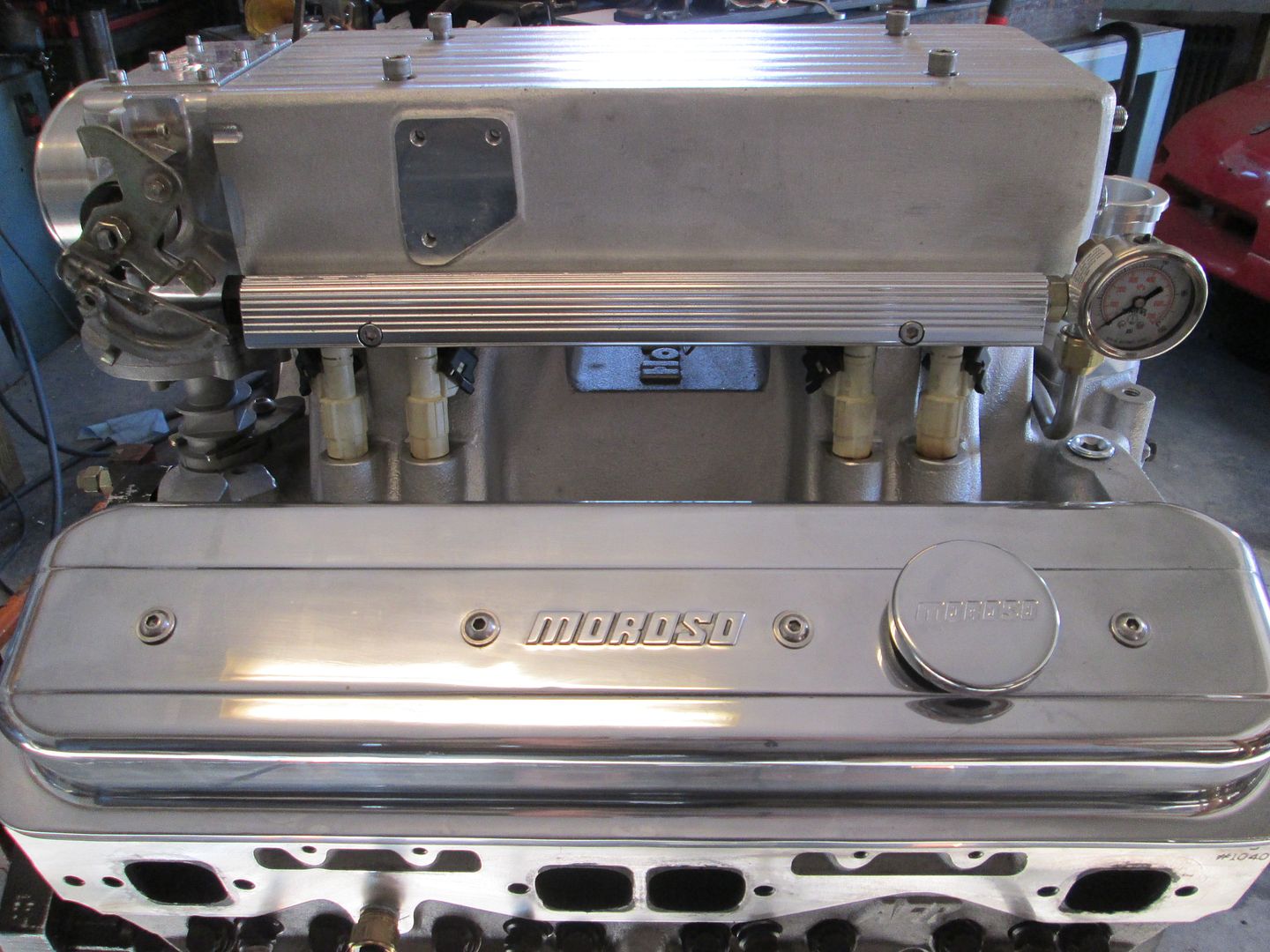
Next order of business for the fuel rail was to add the fuel pressure gauge. Pretty simple with the 1/8 NPT elbow, but when it was tight, the inner portion of the threads were partially blocking the port, so I drilled down through the fitting to clearance the part the protruded into the opening.
Threads protruding:
Clearanced:
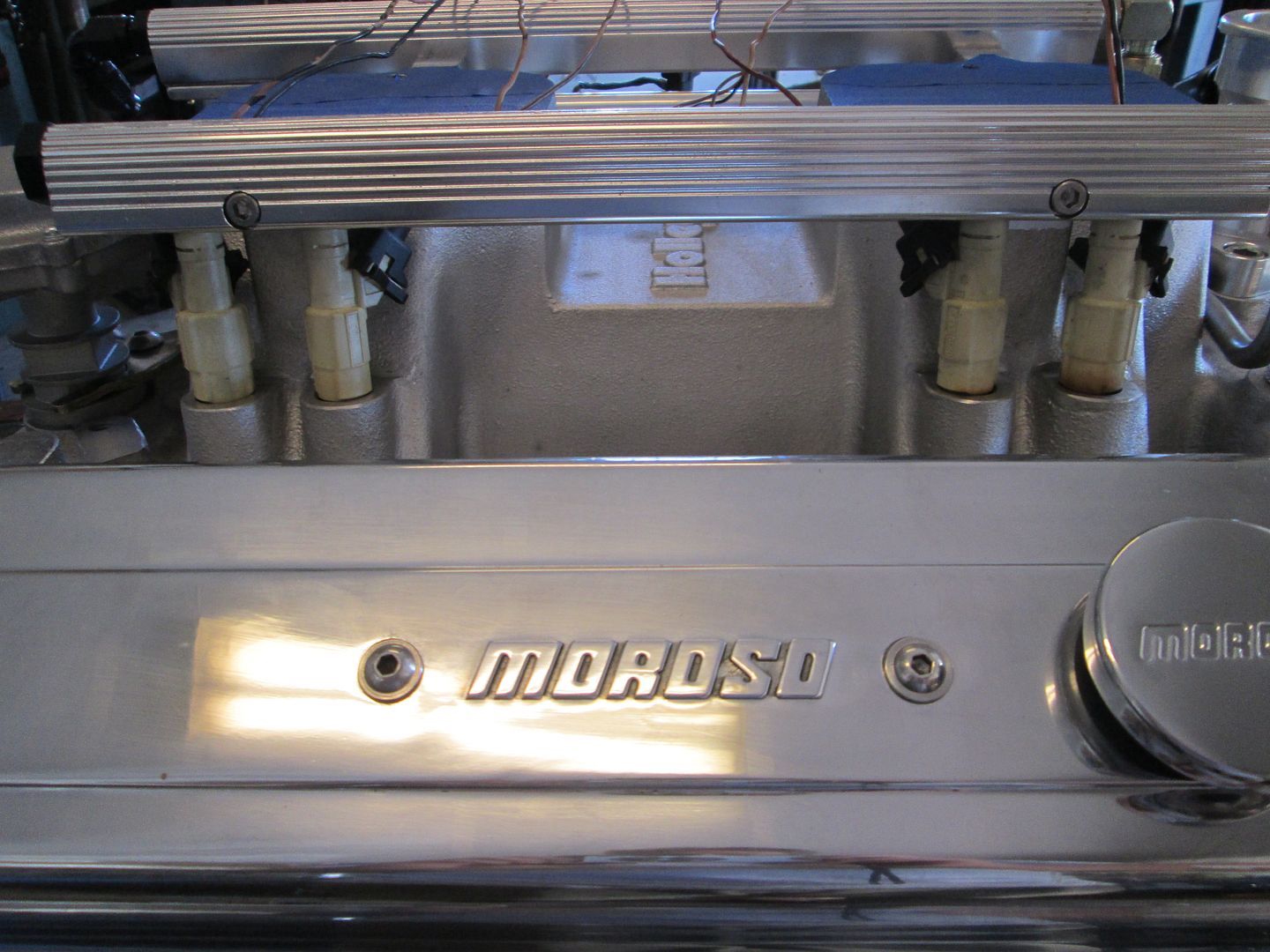
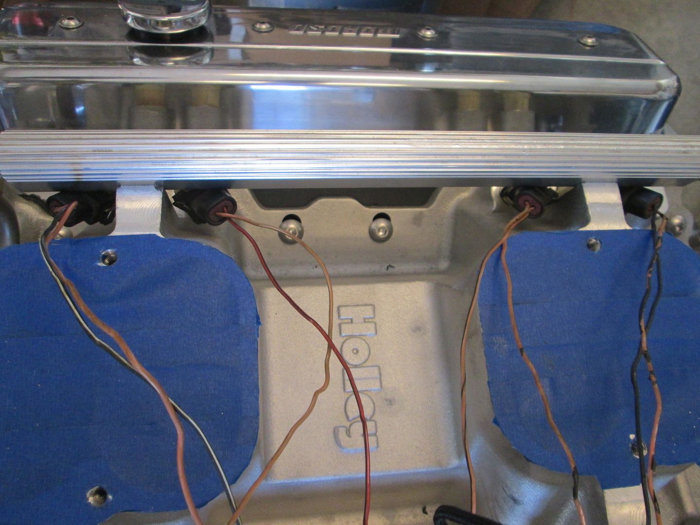
Then purged all the fuel rails and fittings with brake clean to remove any debris, installed the injectors (36# Bosch) and started playing around with wiring options to hide the connectors. Originally I didn't think there was any chance of flipping the connectors to the back side, but it works!
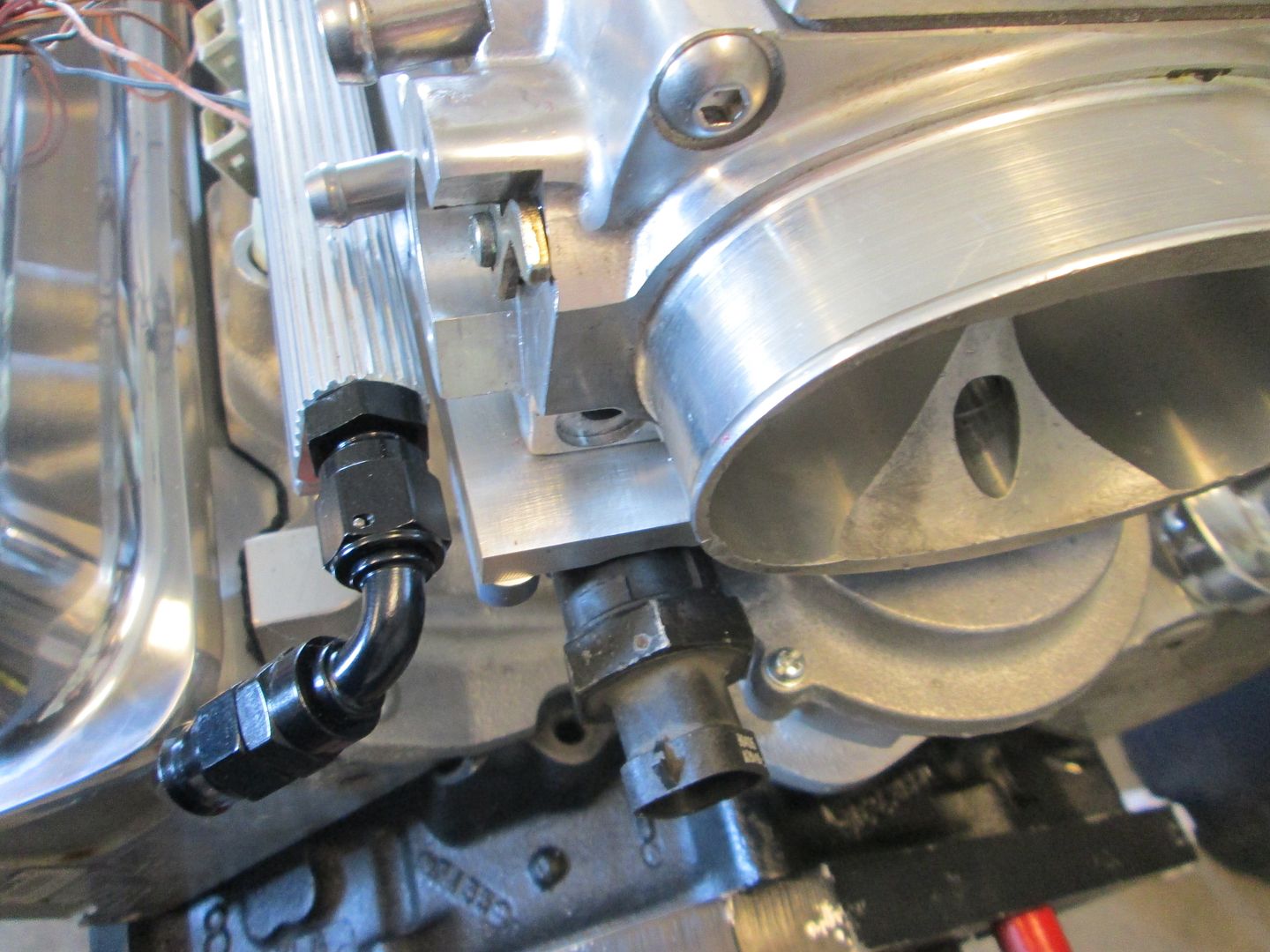
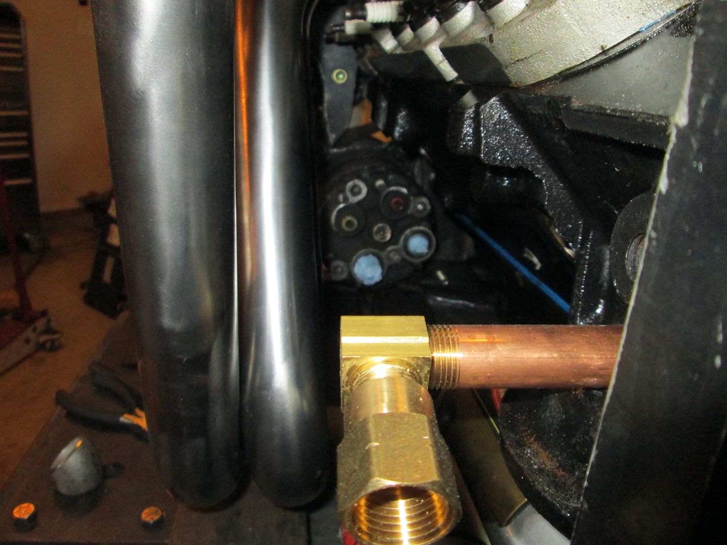
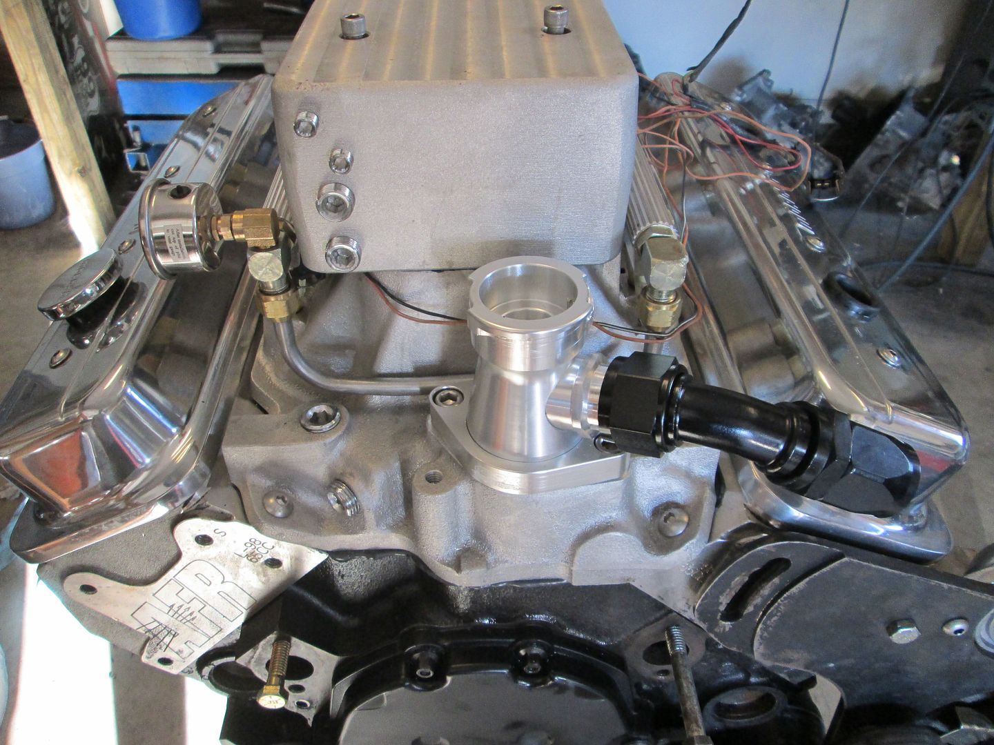
I am in the process of filling all the extra coolant ports and vacuum ports with chrome plugs. This picture also shows the coolant fill and the -16 AN fitting.
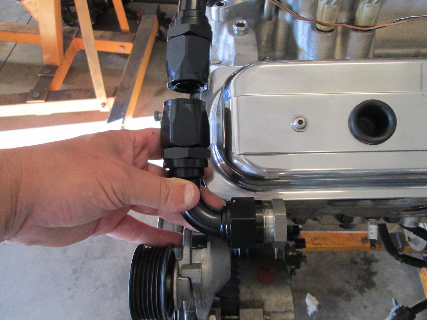
Here is the other -16AN elbow and a steel weld end, there wont be much length to the braided stainless steel hose... I will weld the steel end to some 1" schedule 40 pipe that will be the coolant crossover to the passenger side.
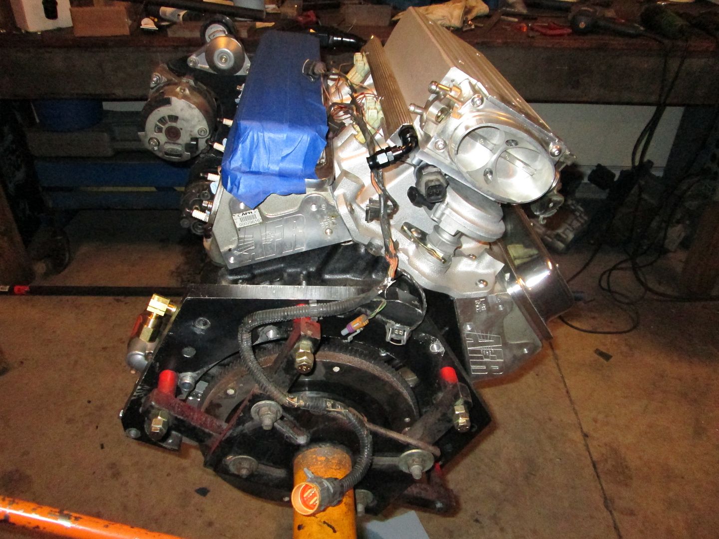
Here is a mockup of the 1 3/4" header flange to the exhaust ports on the heads (I have sense removed the stock fiero temp sender and capped that coolant port):
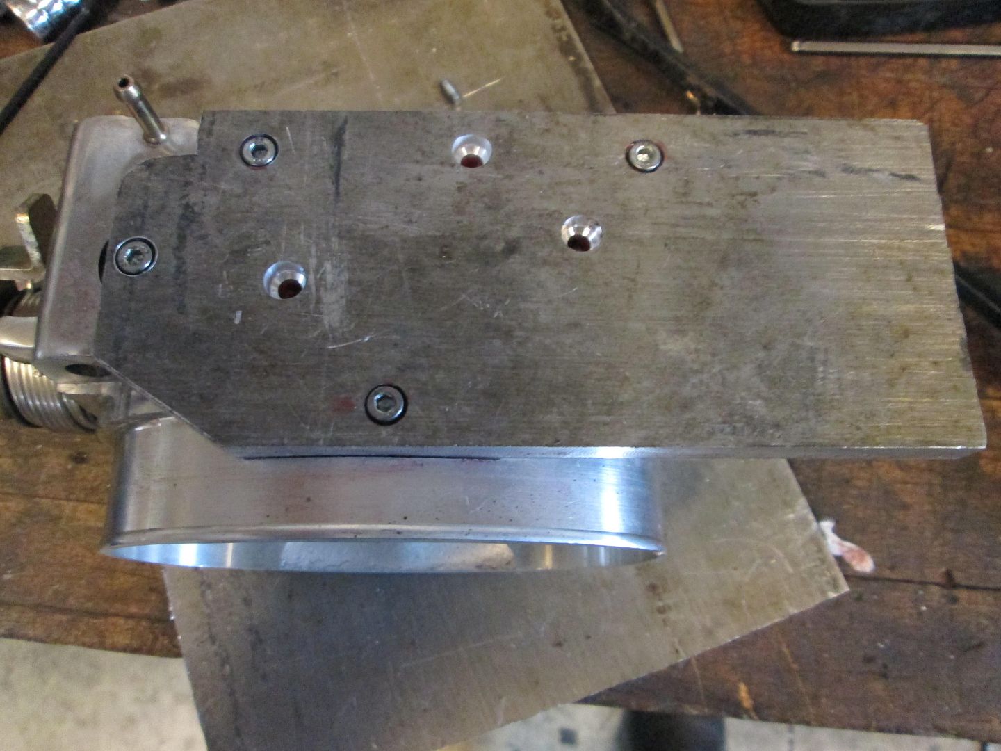
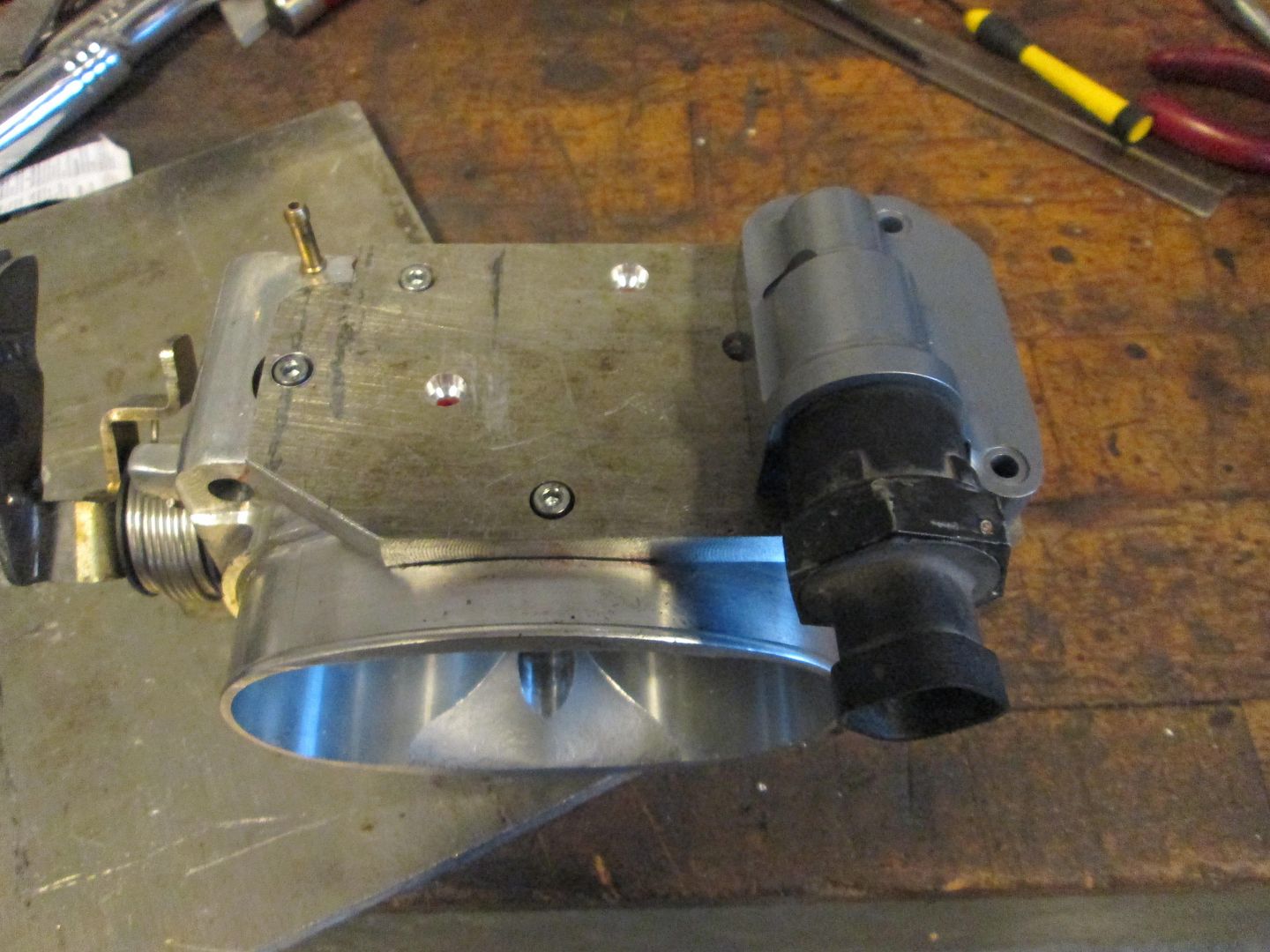
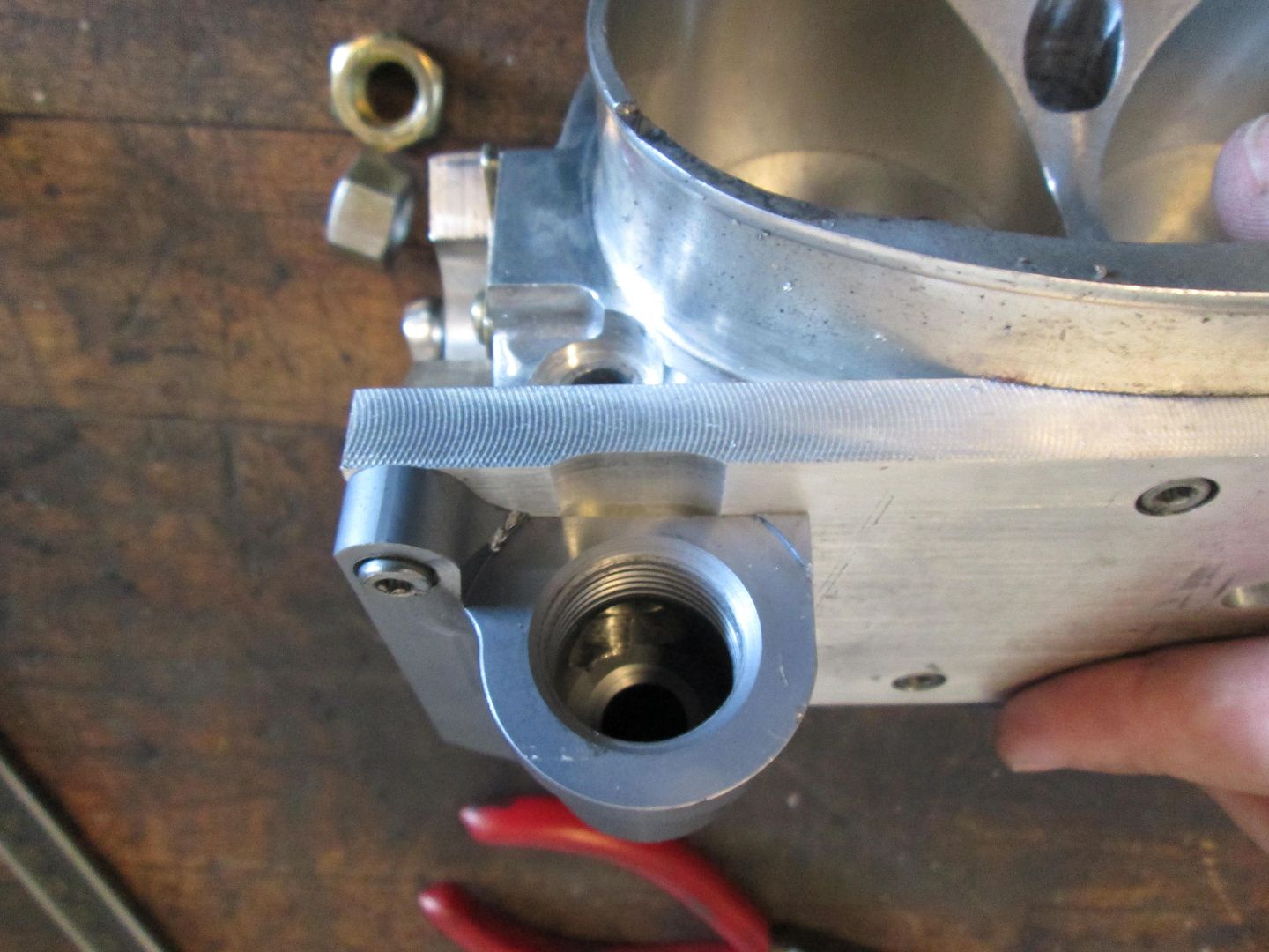
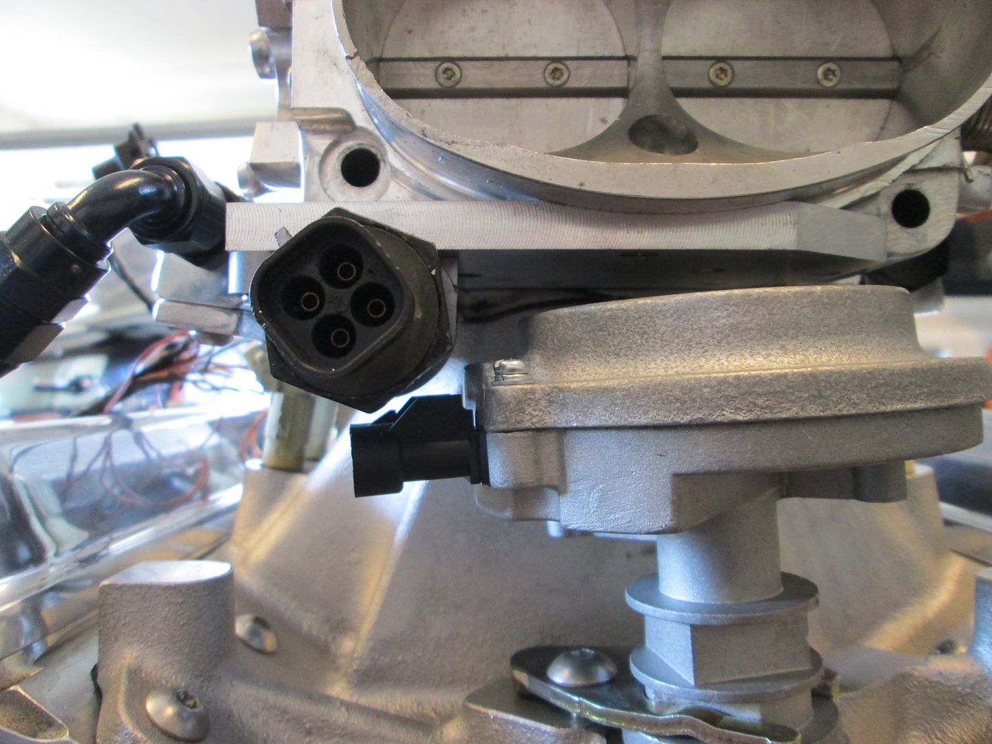
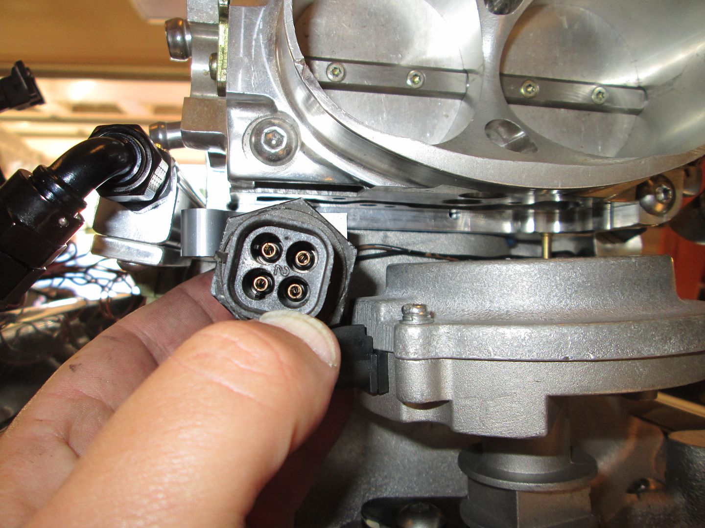
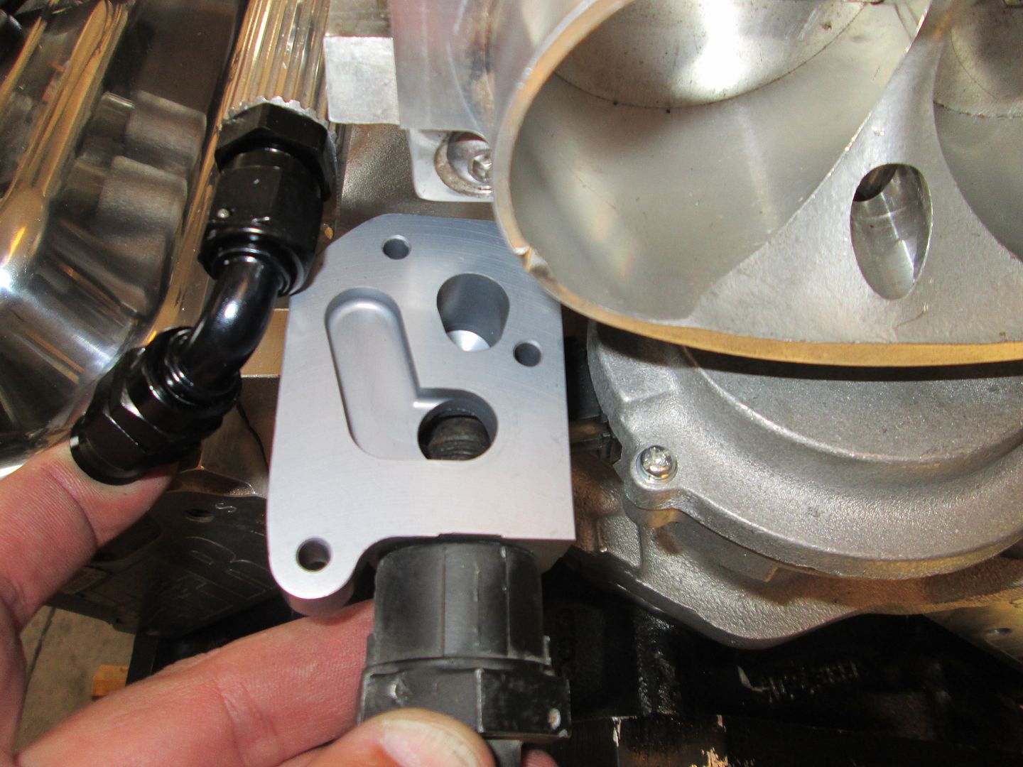
I think I also figured out a slick/relatively simple solution for the IAC housing that will not fit in the stock location. I plan to machine a 1/4" plate to cap off the complete underside of the throttle body housing and extend it out past the TPS side of the throttle body as needed. Then I will use and modify the existing passages under the throttle body (and machine some in the 1/4" plate), to create the air flow path to the new IAC position, which will be 90 degrees from the stock position and off to the side of the throttle body. This pic shows the new position for the IAC housing and the available room for a 1/2" plate:
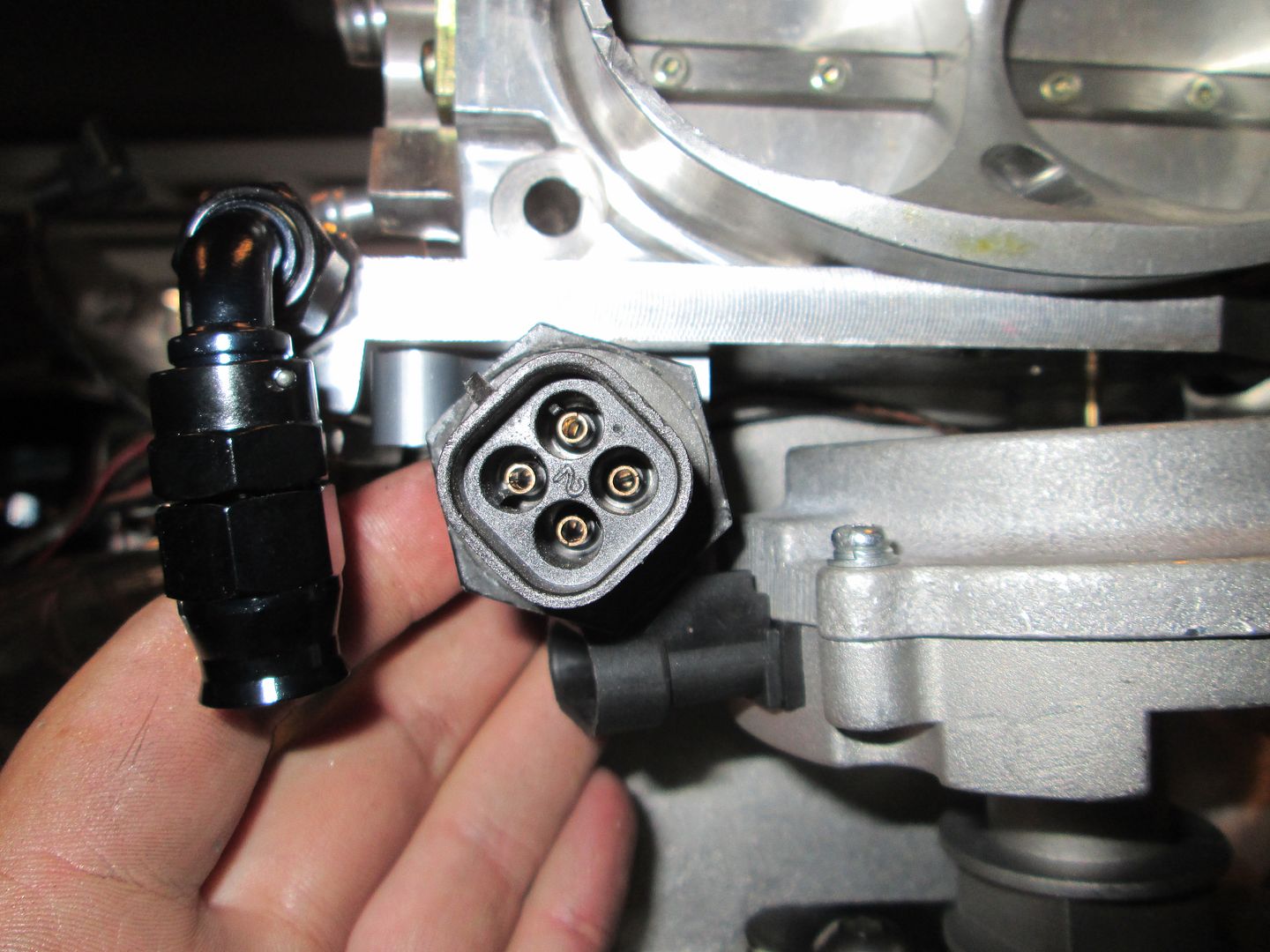
Here is a pic of the ports on the IAC housing:
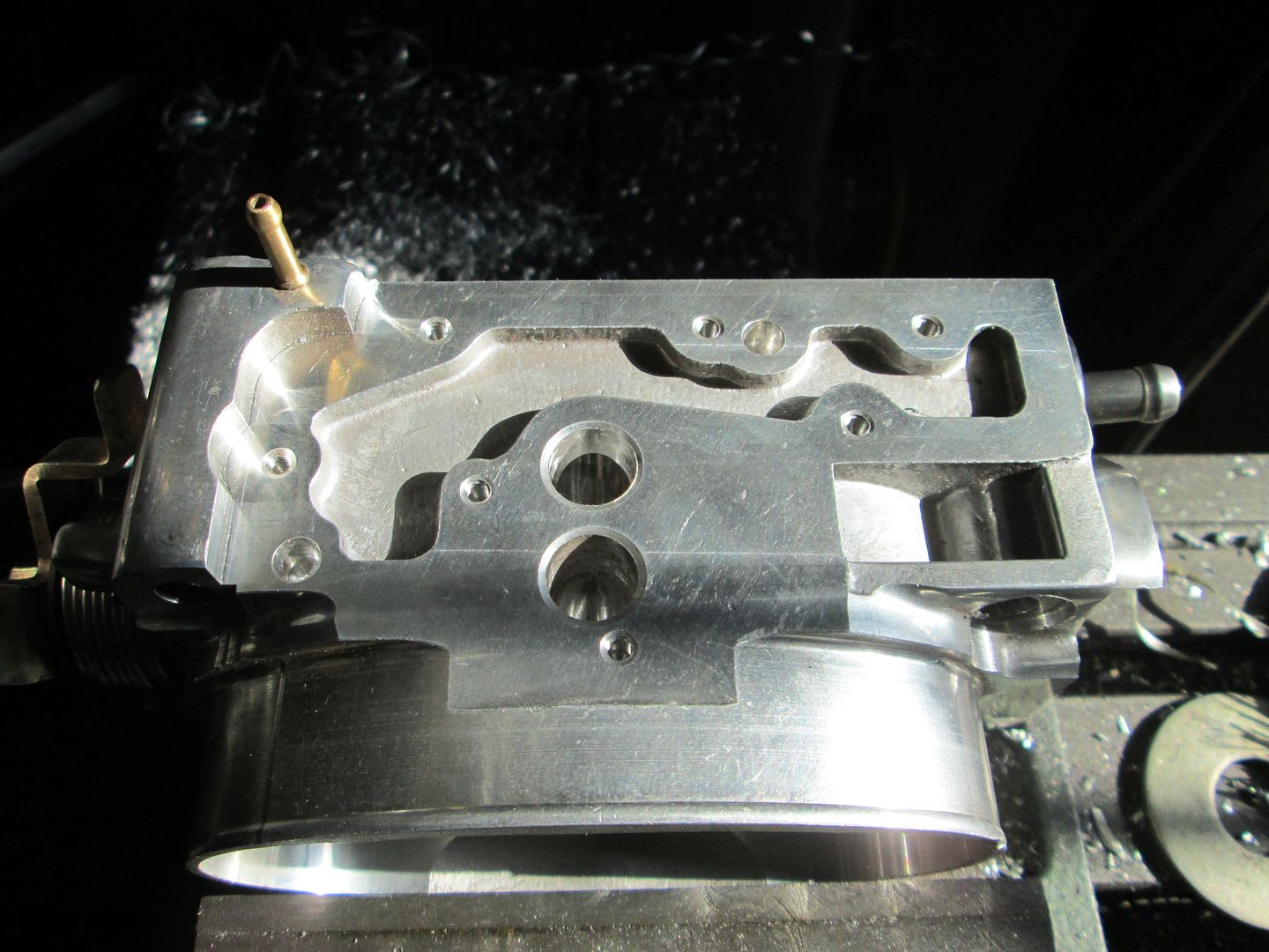
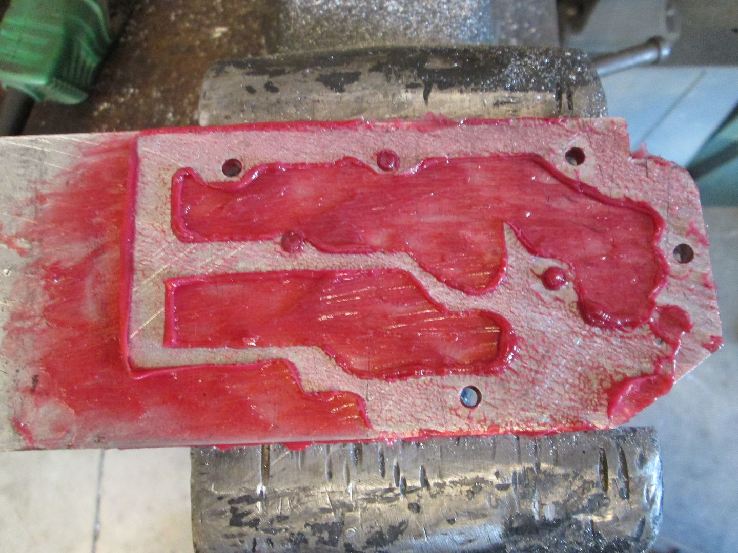
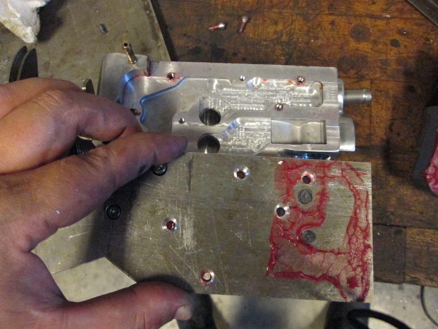
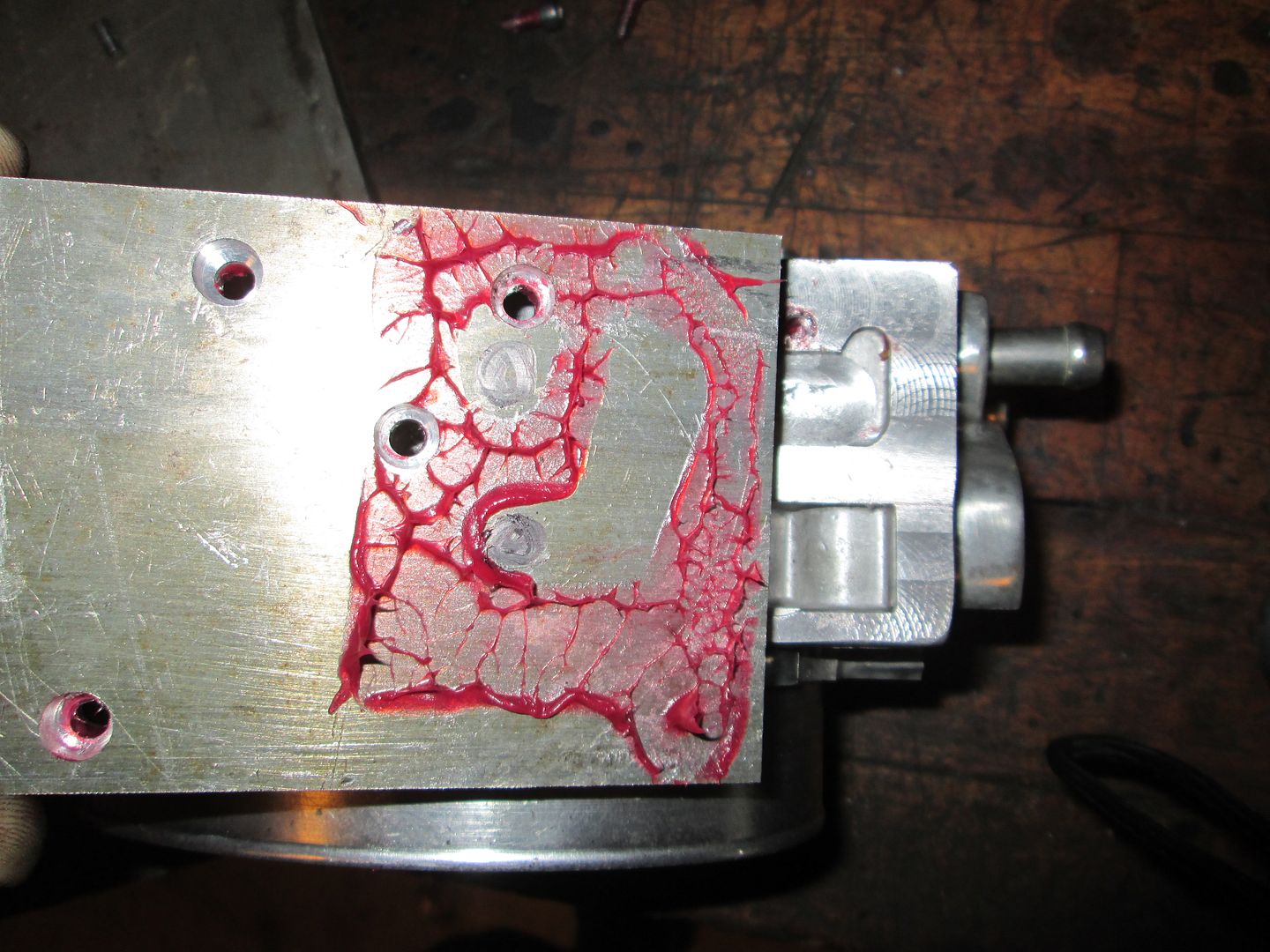
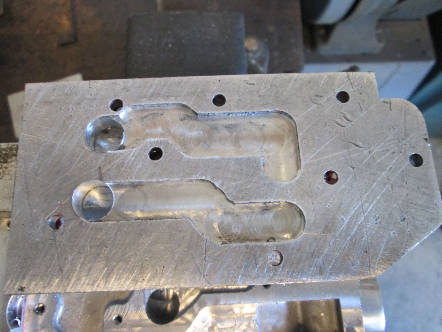
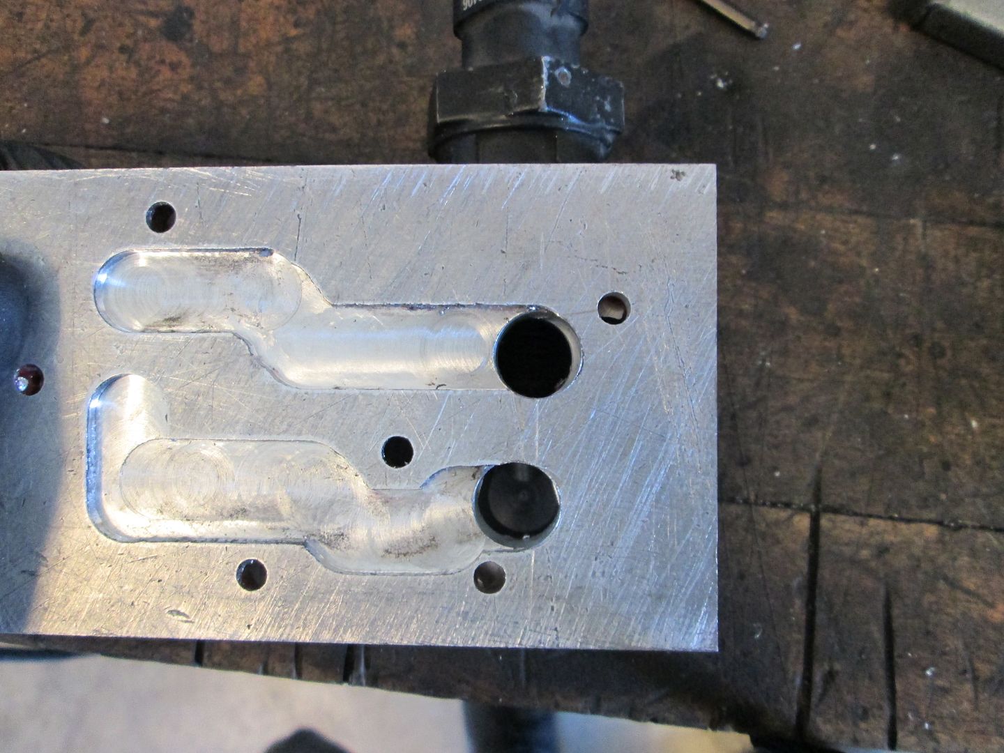
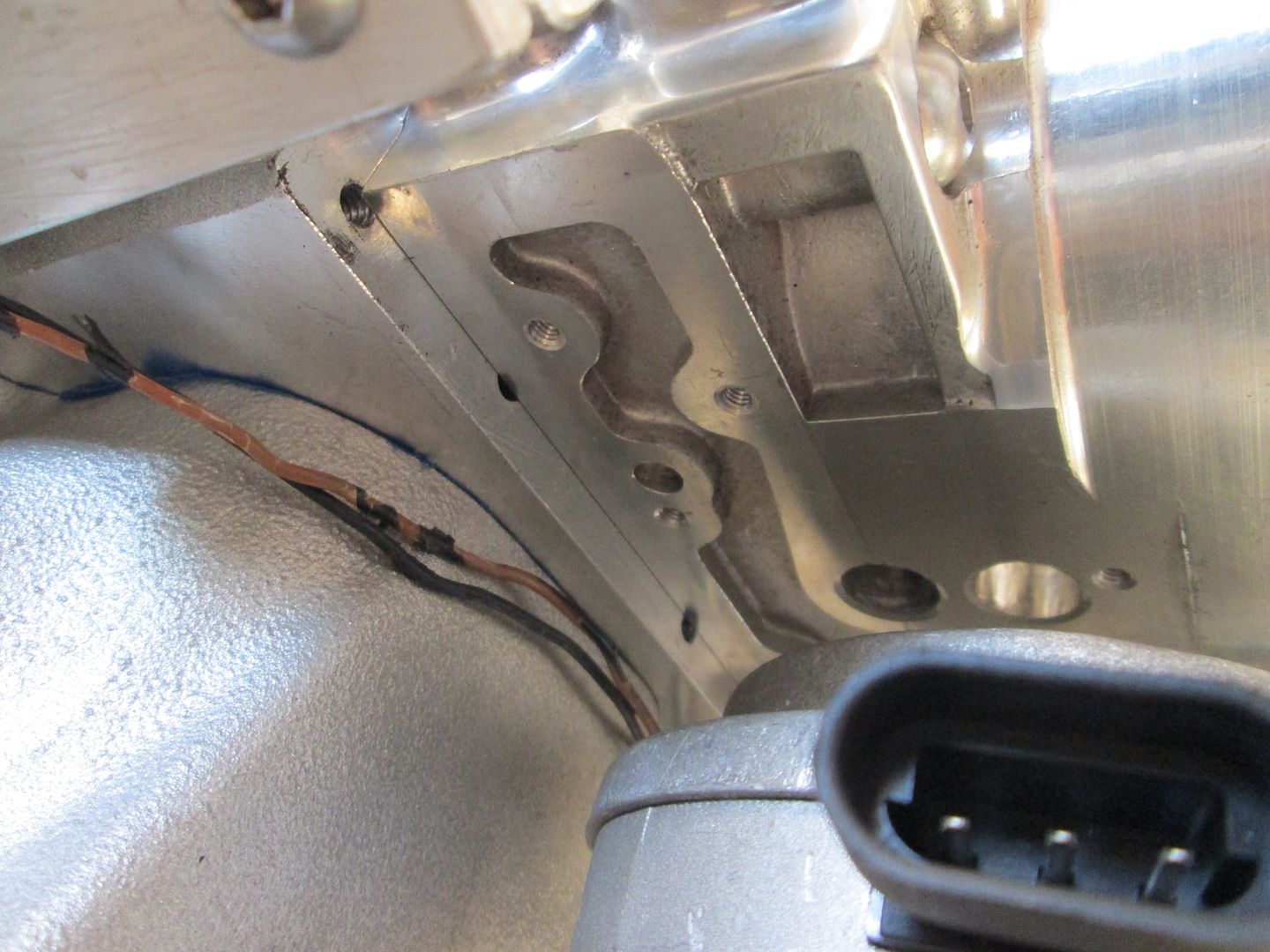
Here is an underside picture of the existing passages in the throttle body. I will need to face it down to the as cast corner so it will seal up well. Then cut a path from the port on the right to the right corner pocket. Then cut a passage from the port on the left to the existing passage on the left:
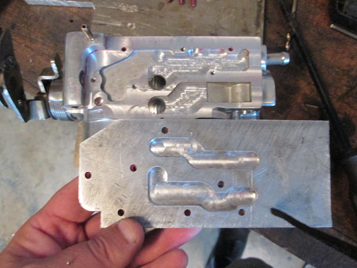
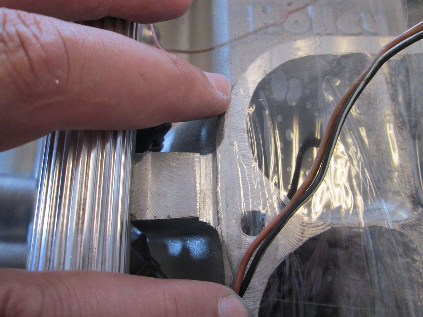
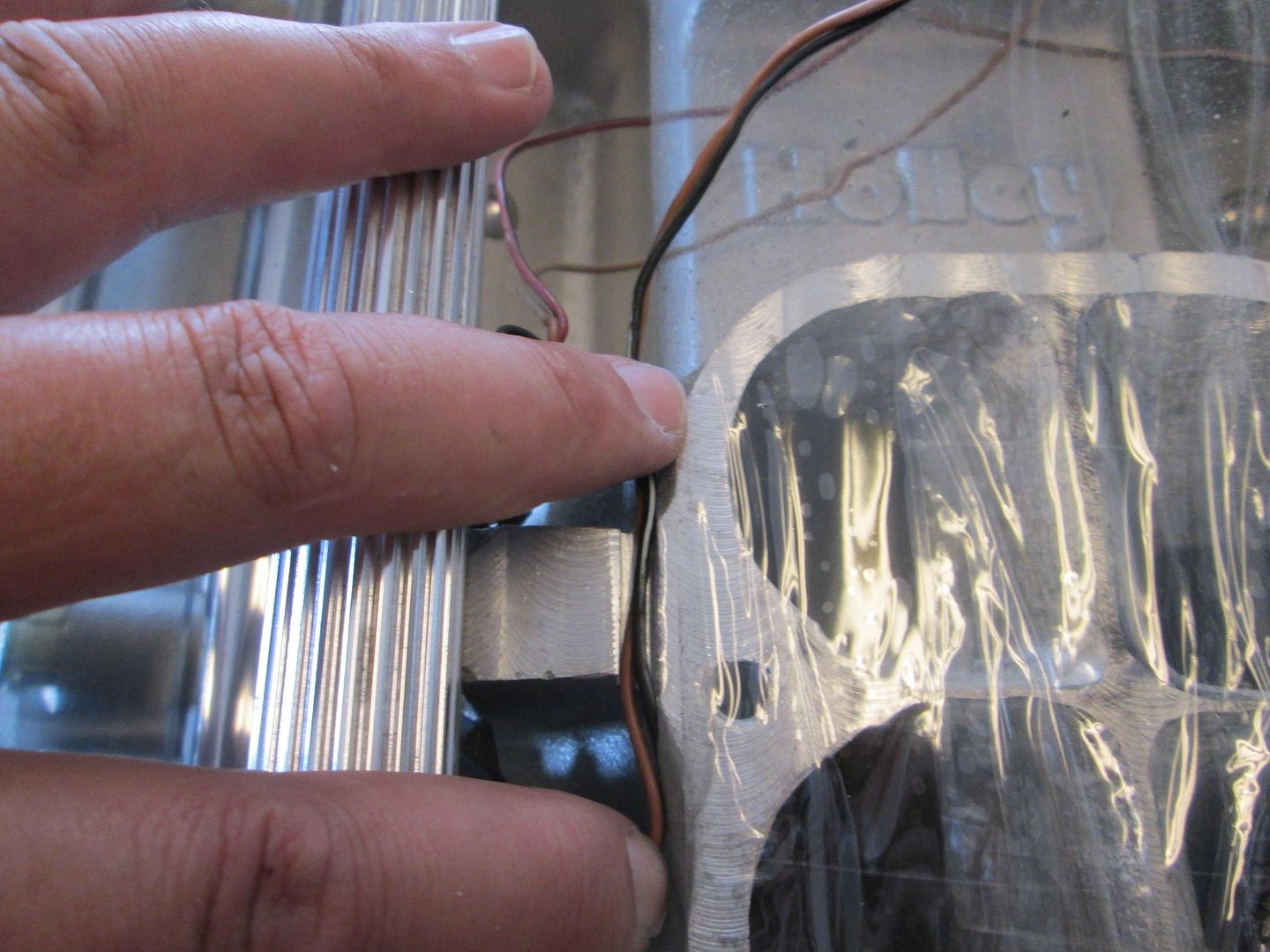
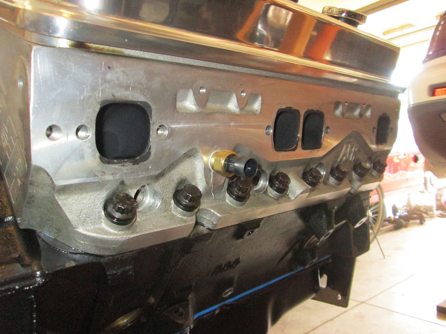
I don't like seeing wires, but sometimes there is only 1 optimal location for the sensor to go. I am referring to the engine coolant temp sensor. My philosophy is the ECM should see the hottest portion of the engine, so it can start pulling timing when needed to protect the engine. If it sees a cooler portion of the engine, it might not see the hottest cylinder and not intervene to protect it. For the SBC (and the LSx engine as well) the hottest location with a coolant port is between cylinders 8 & 6. To keep sensors and wiring minimized, I am using a 3 wire sensor that will provide the needed signal to the ECM as well as the stock fiero temp gauge. The ECM will have 100% control over the fan, so no other coolant sensor or switch is needed.
It will probably be Wednesday before I get back to Vince's car...
[This message has been edited by fieroguru (edited 09-22-2013).]
Yeah, progress has been slow the last few weeks due to LS Fest and spending time on my car, working on quite a few brake kit orders, and last week we had plant dinners on all shifts on 2 days (4 crew plant) so I was working some very strange hours... However Vince's engine did get some love this weekend.
I had already installed the timing cover for the last time, made a timing notch for TDC (just to assist with positioning the cam sensor), and installed the oil pan with a new gasket:
Next I wanted to button up the valve covers, so I swapped out the roller tipped 1.52 ratio rockers with the 1.6 roller tipped rockers. With these, his roller camshaft specs are: 230/236 .576"/.570" with a 113 lobe separation (Comp Cams 280XFI HR13 part # 07-467-8). With his AFR heads flowing more at .600 than .550, he should see some additional peak HP and possibly push this thing over 400 wph (371 whp was the previous tune). Here are the 1.5 roller rockers:
Comparison pic (1.6 on the left):
Installed:
The bolts for the valve covers were about 1/4" too long to tighten the valve covers, so I shortened the 8 bolts, dumped a quart of oil over each bank and installed the valve covers. Next was to install the lower intake, I dumped 2 quarts of oil over the lifters, installed the intake gaskets, installed the intake, lined up the intake runners to the head ports (with a tunnel ram you can "see" the alignment), then torqued it down. All the ports looked like these two with just a slight portion of the lower corners of the head protruding past the ports on the HSR.
All of this work to button up the engine was to finalize the cam sensor location in the distributor housing. It took some trial and error to get the sensor lined up with the connector pointing the direction I wanted it, but eventually got there. Then the hold down clamp had to be slotted to the right position, then the original hole welded up and smoothed, the bolt hole redrilled, and a pivot stand welded to the hold down... Now the cam sensor is aligned per the EFI Connection instructions!
Hold down slotted:
Filled:
Smoothed and redrilled:
Installed:
Next I set to work on the fuel rails. They are setup for a rail mounted regulator and I am converting them to returnless, so I needed to fill the regulator port. I turned a plug with the same o-ring groove as the regulator, fabbed up an aluminum bar to span the plug and keep it secure, then trimmed the stainless steel button heads to the right length.
Bypass regulator and open port:
Turning a plug with o-ring groove:
Installed:
Capped:
Next order of business for the fuel rail was to add the fuel pressure gauge. Pretty simple with the 1/8 NPT elbow, but when it was tight, the inner portion of the threads were partially blocking the port, so I drilled down through the fitting to clearance the part the protruded into the opening.
Threads protruding:
Clearanced:
Then purged all the fuel rails and fittings with brake clean to remove any debris, installed the injectors (36# Bosch) and started playing around with wiring options to hide the connectors. Originally I didn't think there was any chance of flipping the connectors to the back side, but it works!
I am in the process of filling all the extra coolant ports and vacuum ports with chrome plugs. This picture also shows the coolant fill and the -16 AN fitting.
Here is the other -16AN elbow and a steel weld end, there wont be much length to the braided stainless steel hose... I will weld the steel end to some 1" schedule 40 pipe that will be the coolant crossover to the passenger side.
Here is a mockup of the 1 3/4" header flange to the exhaust ports on the heads (I have sense removed the stock fiero temp sender and capped that coolant port):
I think I also figured out a slick/relatively simple solution for the IAC housing that will not fit in the stock location. I plan to machine a 1/4" plate to cap off the complete underside of the throttle body housing and extend it out past the TPS side of the throttle body as needed. Then I will use and modify the existing passages under the throttle body (and machine some in the 1/4" plate), to create the air flow path to the new IAC position, which will be 90 degrees from the stock position and off to the side of the throttle body. This pic shows the new position for the IAC housing and the available room for a 1/2" plate:
Here is a pic of the ports on the IAC housing:
Here is an underside picture of the existing passages in the throttle body. I will need to face it down to the as cast corner so it will seal up well. Then cut a path from the port on the right to the right corner pocket. Then cut a passage from the port on the left to the existing passage on the left:
I don't like seeing wires, but sometimes there is only 1 optimal location for the sensor to go. I am referring to the engine coolant temp sensor. My philosophy is the ECM should see the hottest portion of the engine, so it can start pulling timing when needed to protect the engine. If it sees a cooler portion of the engine, it might not see the hottest cylinder and not intervene to protect it. For the SBC (and the LSx engine as well) the hottest location with a coolant port is between cylinders 8 & 6. To keep sensors and wiring minimized, I am using a 3 wire sensor that will provide the needed signal to the ECM as well as the stock fiero temp gauge. The ECM will have 100% control over the fan, so no other coolant sensor or switch is needed.
It will probably be Wednesday before I get back to Vince's car...
I understand the jealousy... But why quote the whole long post, just to say it? It kinda muddies the thread when a post with 25-30 pictures is quoted in full...
[This message has been edited by carbon (edited 09-23-2013).]
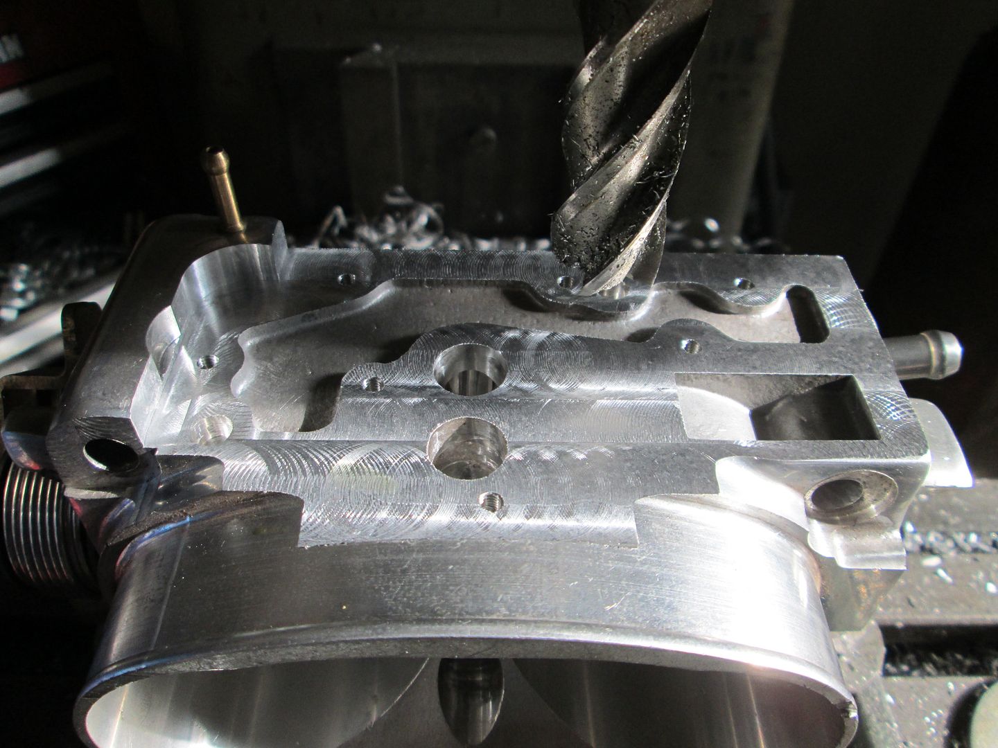
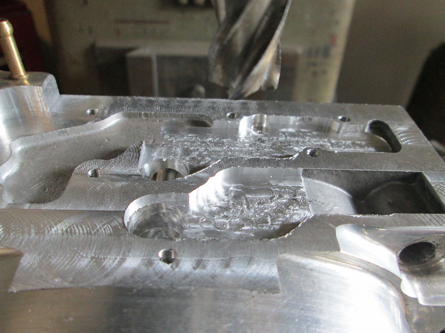
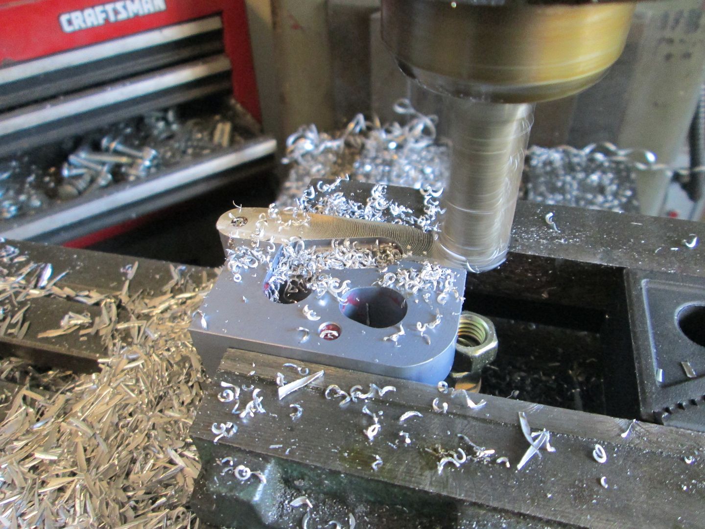
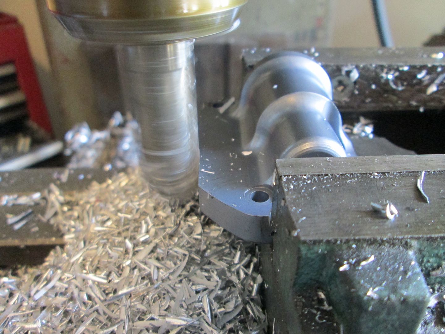
Milling the bottom surface flat, then the slots from the IAC ports to the edge:
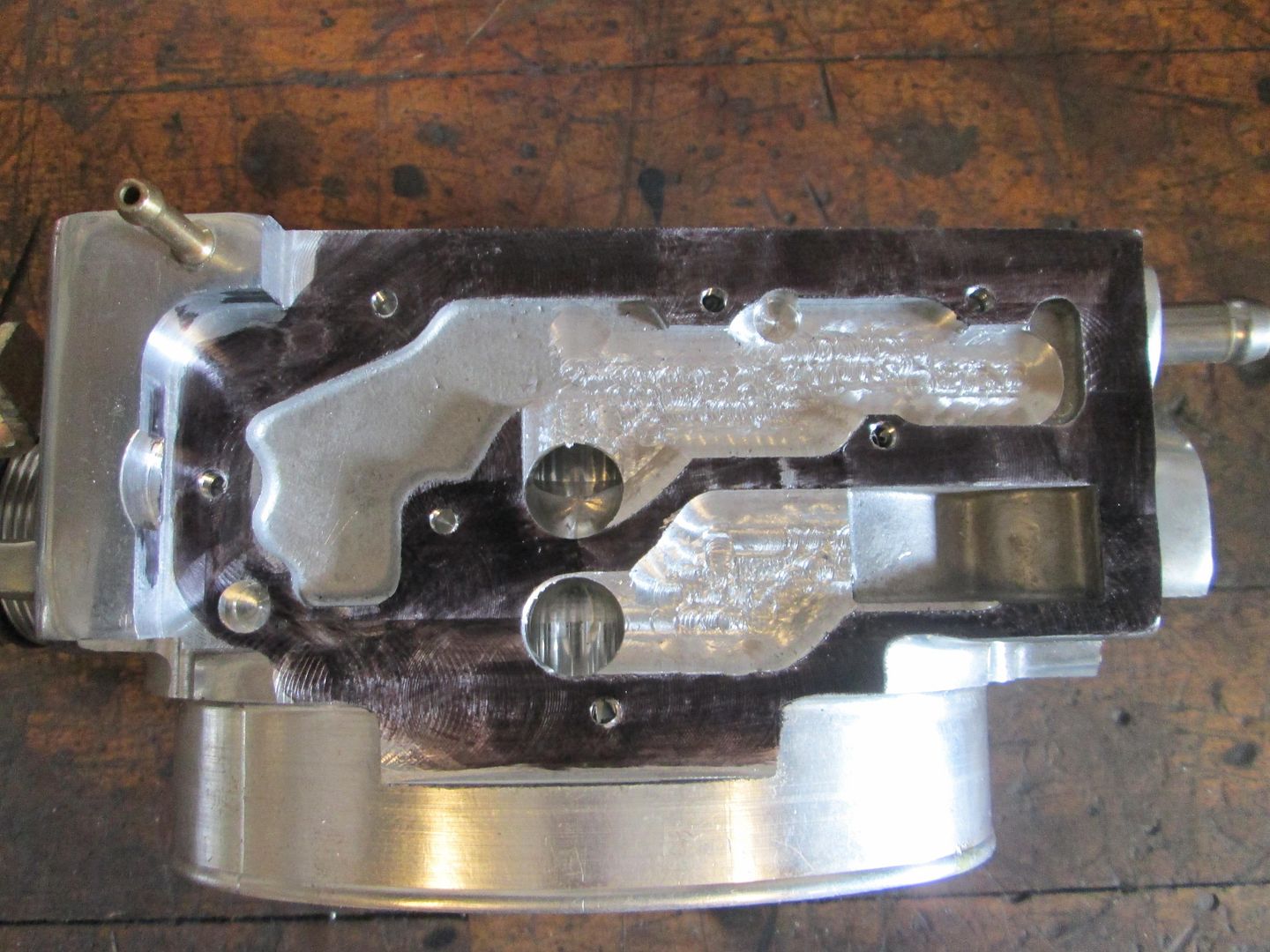
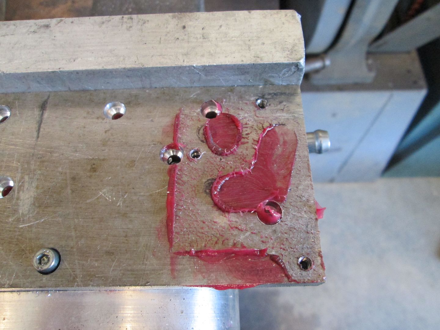
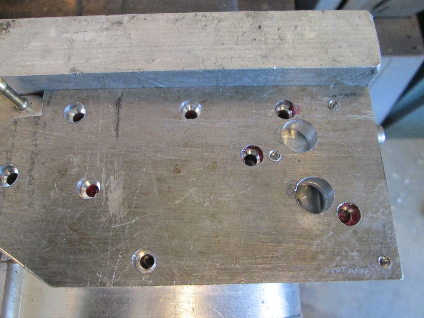
Here I used a marker to show the flange area and the new air passages:
Then I cut out a piece of 3/8" aluminum plate, cut it to shape, located and drilled all the bolt holes. Then used some grease to transfer the port pattern from the throttle body.
Then milled the passages in the aluminum plate:
Then I trimmed the side to clear the fuel rail and checked everything for clearance:
Here is where the IAC will be on the underside. I do need to mill the plate or the IAC housing to get more clearance to the connector on the distributor:
I used the grease (and black marker) to show the port locations in the IAC and how they line up with the passages in the bottom of the throttle body:
I still need to drill/tap the mounting holes in the plate for the IAC, drill the plate and tap the throttle body for another bolt in the far corner, then either mill the IAC housing or the plate for more connector clearance... then I can move on to the next challenge.
Wow! That's crazy all that you had to do for just that one part.
Too bad there's no simple way of flipping the whole throttle body upside down. :/
Sorry you're getting stuck with all these little mods!
I am a little weird in that I really like/enjoy these challenging fitment issues. Just bolting parts together gets boring, fitment issues like this keep things interesting. Plus, these are the items that will keep your swap unique! I like this IAC solution much better than some of the other ones we had discussed as its quite simple and keeps things hidden without having to add additional plumbing that could have been a distraction.
Originally posted by Trinten: Okay, I'm glad you're not finding them tiresome or a nuisance!
Those are the details that makes this a "Fieroguru Special"...and the reason he has the car rather than someone else.
Personally, the details of this build mean a lot more to me than the other threads Fieroguru has done. Sure, there is good automotive p0rn in all of them....but so much more fun watching the p0rn when the star is a chick you went to school with (or maybe I am just sick and twisted...your call on that one).
[This message has been edited by CowsPatoot (edited 09-26-2013).]
This thread should be in the "Technical Discussion" or atleast in the "Construction" section, there is nothing "General" about this project.... Great work Guru!
Those are the details that makes this a "Fieroguru Special"...and the reason he has the car rather than someone else.
Personally, the details of this build mean a lot more to me than the other threads Fieroguru has done. Sure, there is good automotive p0rn in all of them....but so much more fun watching the p0rn when the star is a chick you went to school with (or maybe I am just sick and twisted...your call on that one).
... what did I just read? I don't even... lol
quote
Originally posted by TXOPIE:
^ I would have to 2nd that!
Thanks, I think waaay back when this started with the first set of guys, I didn't pay enough attention to put it in the builds section - or it was one of those things that had to be declared worthy enough to be put there. As for the Technical section, again at the time, I didn't feel there was enough to merit it being in the technical section, it was pretty straight forward.
Now that Guru has it, it's a different story, but I'm not going to bug Cliff to move it, he probably gets enough crazy requests - plus he was already kind enough to change the title of the thread for me.
Originally posted by Trinten: ... Now that Guru has it, it's a different story, but I'm not going to bug Cliff to move it, he probably gets enough crazy requests - plus he was already kind enough to change the title of the thread for me.
From: The Construction Zone "There are so many great build threads and other write-ups out there, it warrants its own section! You can't start threads here, but if your thread is worthy enough, it will eventually end up here."
It'll get there. I think Cliff goes through the threads from time to time.
[This message has been edited by Raydar (edited 09-28-2013).]
Drilled/tapped the corner hole in the area that wasn't originally part of the IAC housing (and an as cast surface). Sorry, no good picture at the moment.
Milled the IAC housing slightly more than 1/8" to gain more clearance to the connector and also 1/8" off the side to allow it to slide closer to the fuel rail for additional clearance to the connector and to a bolt hole:
Marked and drilled the port holes in the plate:
Milled the slots deeper in the 3/8" plate and milled a notch for the IAC motor to clear the plate (needed since I milled the IAC housing):
Couple of installed pictures:
I am just waiting for the stainless steel M4 - .70 x 10mm socket head bolts to arrive to seal it up for the last time.
[This message has been edited by fieroguru (edited 09-28-2013).]
As always, thank you for the pictures and attention to detail!
I'm still floored by that IAC setup...
I was talking to a guy at work saying how when this is done, I'm going to print out some key posts and pictures, and put together a binder to take with me to car shows to put out so people can see all the little tricks that were done to get this to work. Something to put by the car at AutoFair in the spring, maybe with a self standing placard that says "V8 Fiero - no your friend did not have one with a V8 'from the factory'" then the highlights. lol
Originally posted by Trinten: I'm still floored by that IAC setup...
Glad you like it!
It is one of the key mods for the HSR to fit under the decklid with just a minor notch. If this was a stock height HSR intake, then the IAC mod wouldn't be needed, but then the intake would be taller and require a larger notch to the decklid.
quote
Originally posted by Trinten: I was talking to a guy at work saying how when this is done, I'm going to print out some key posts and pictures, and put together a binder to take with me to car shows to put out so people can see all the little tricks that were done to get this to work.
I had one of those for my Ramjet car and have one for the LS4/F40.
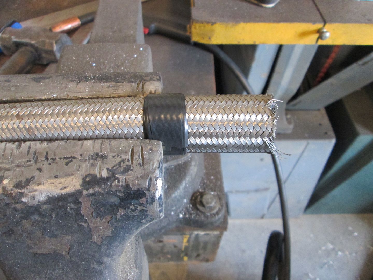
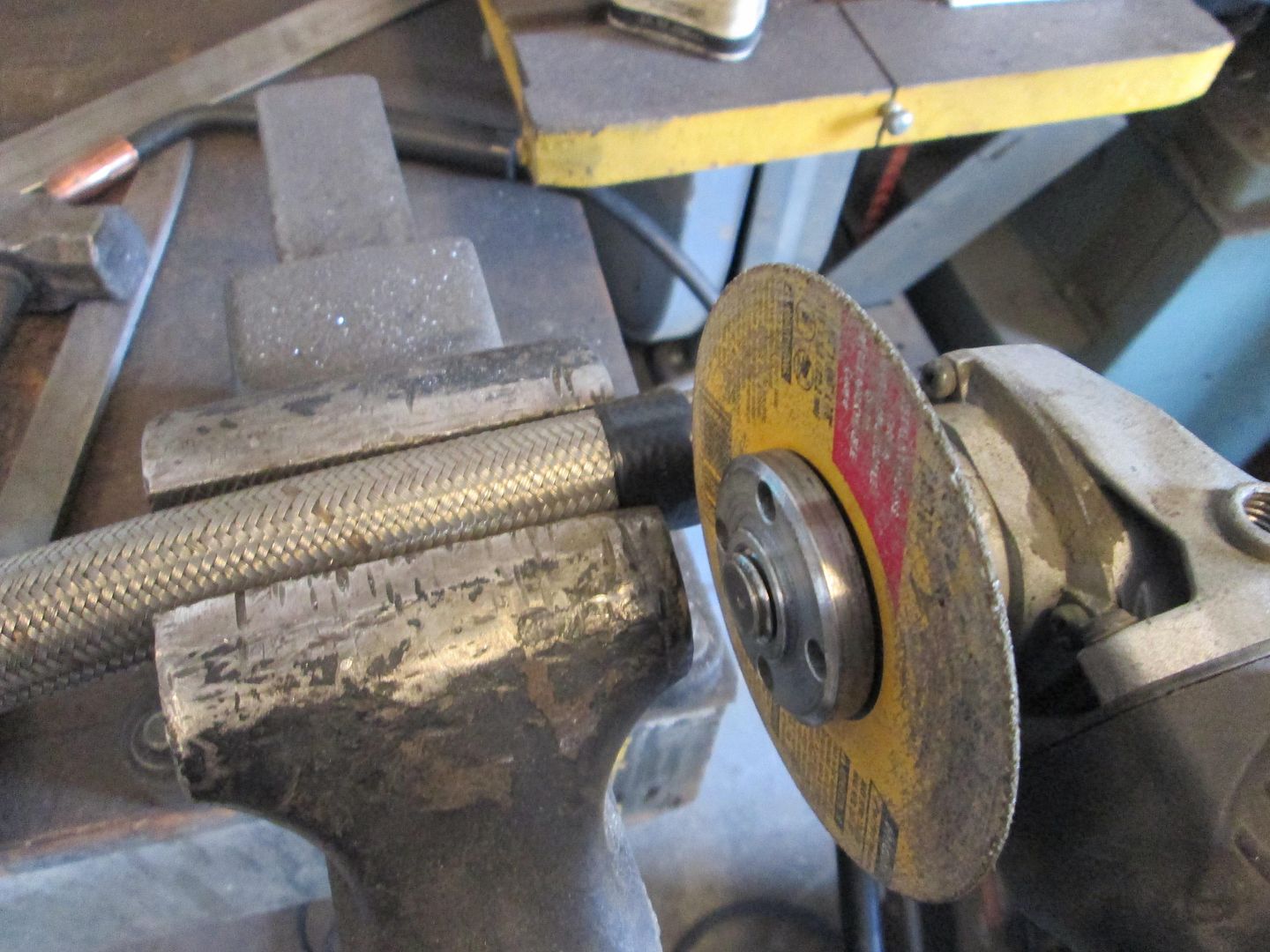
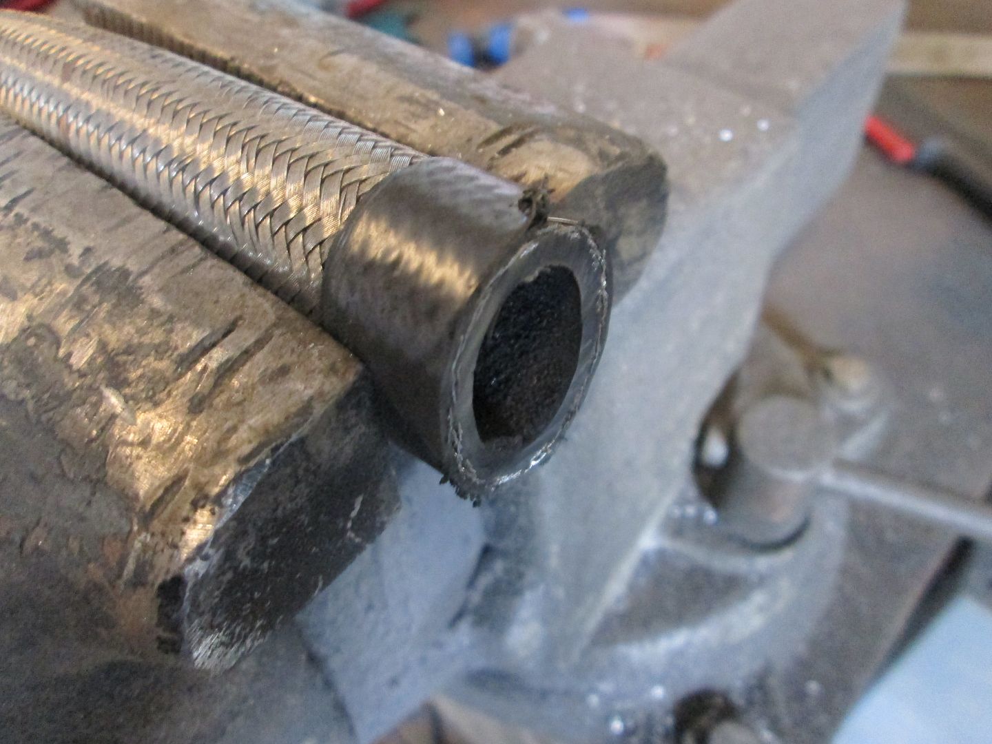
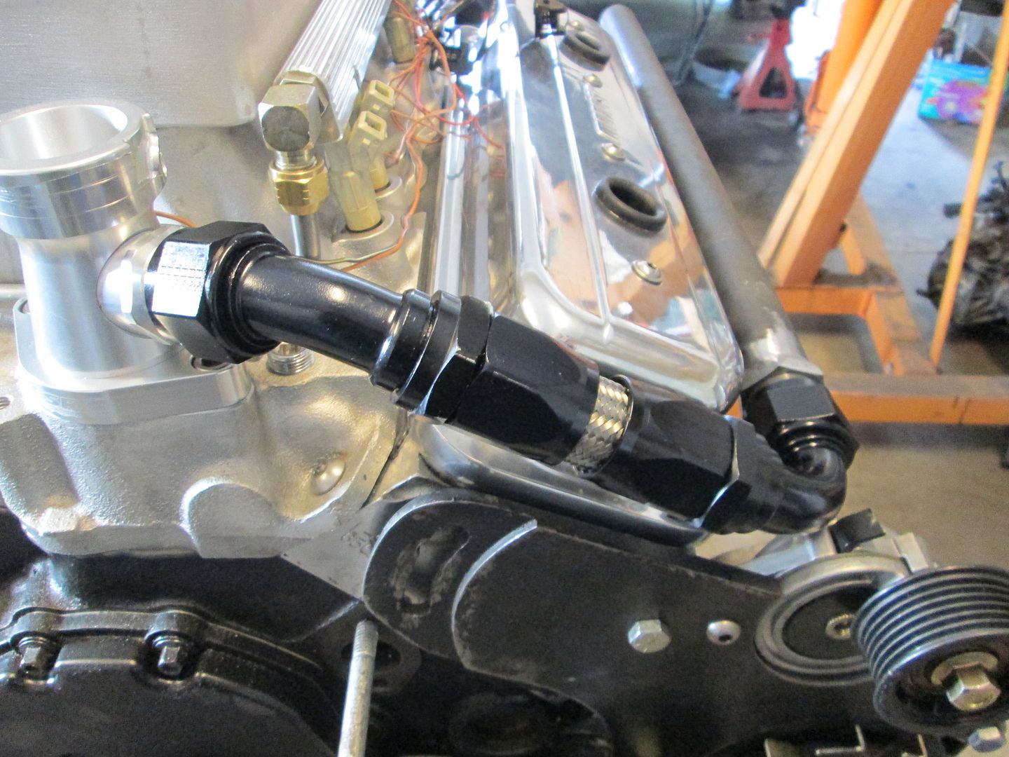
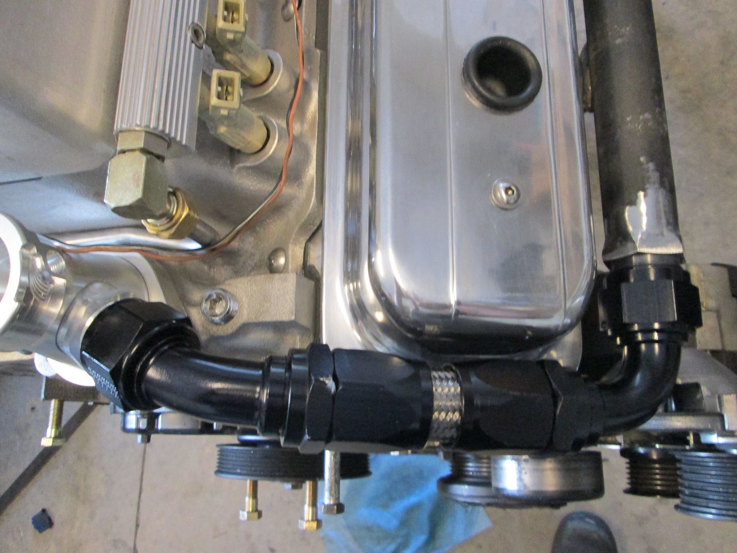
I welded the tabs to the coolant crossover pipe and then fabbed up the -16AN hose between the thermostat housing and the coolant pipe. When I cut the braided stainless hose, I wrap it with electrical tape about 5-7 times, and then cut with a cutoff disk. Clean, lube and assemble:
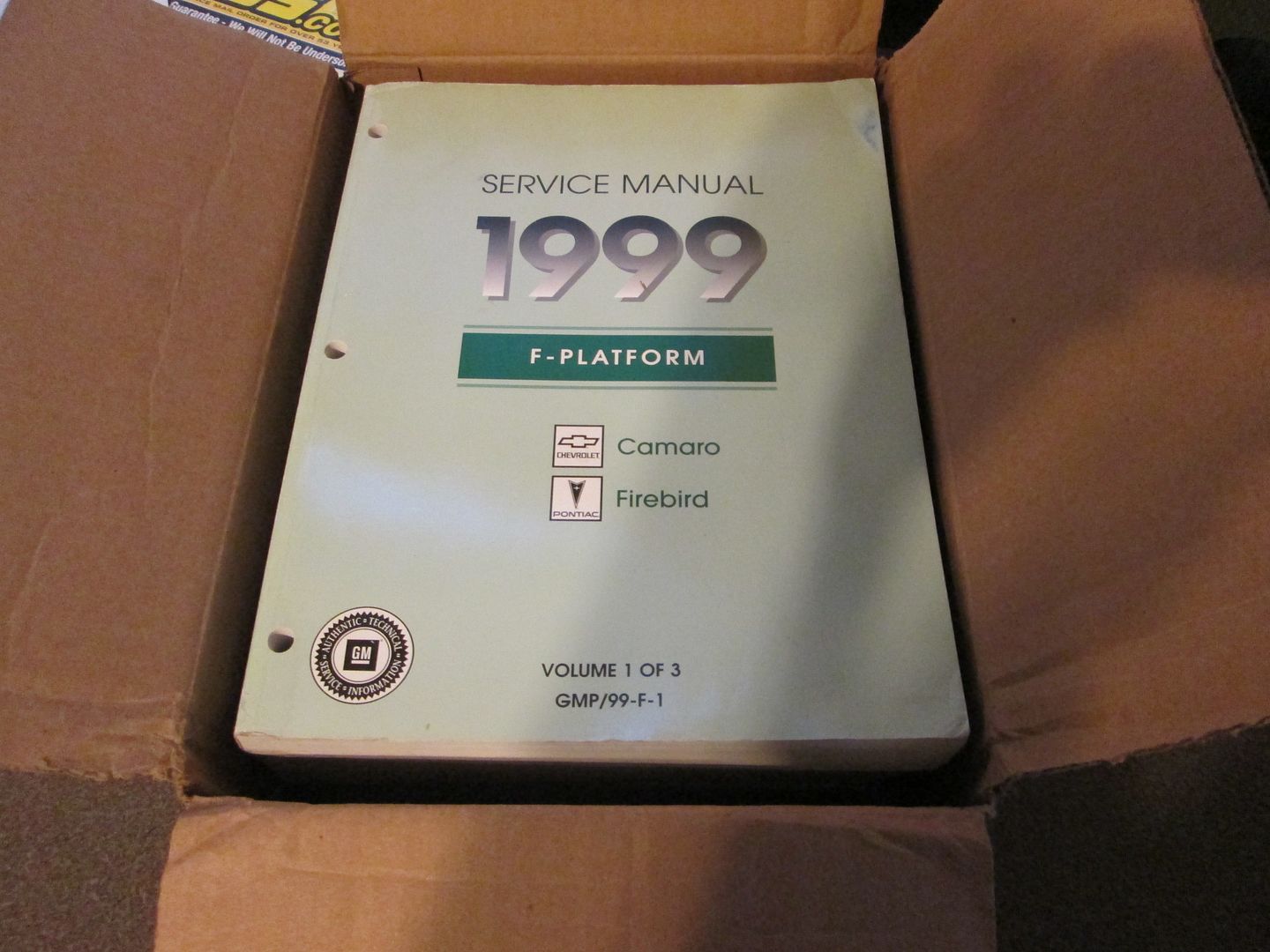
This Fiero is now a 1999 Camaro (or Firebird)... Service manual for the wiring side of things.
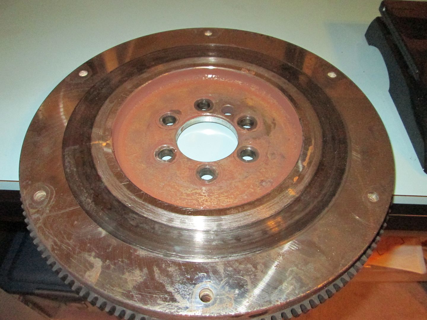
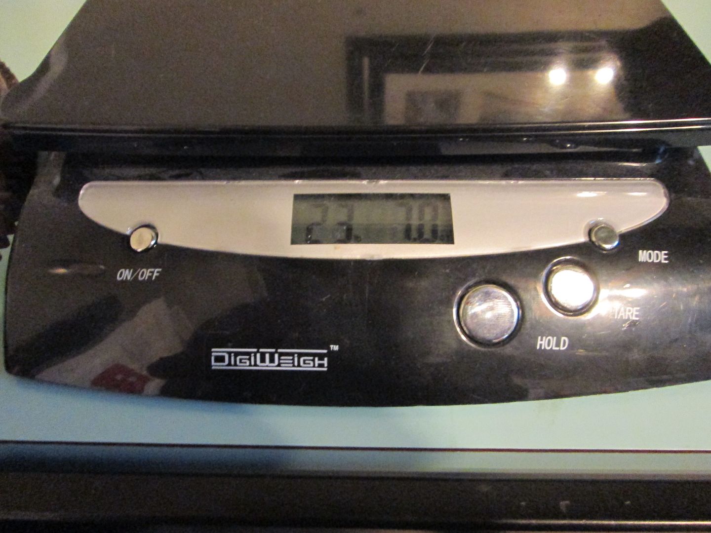
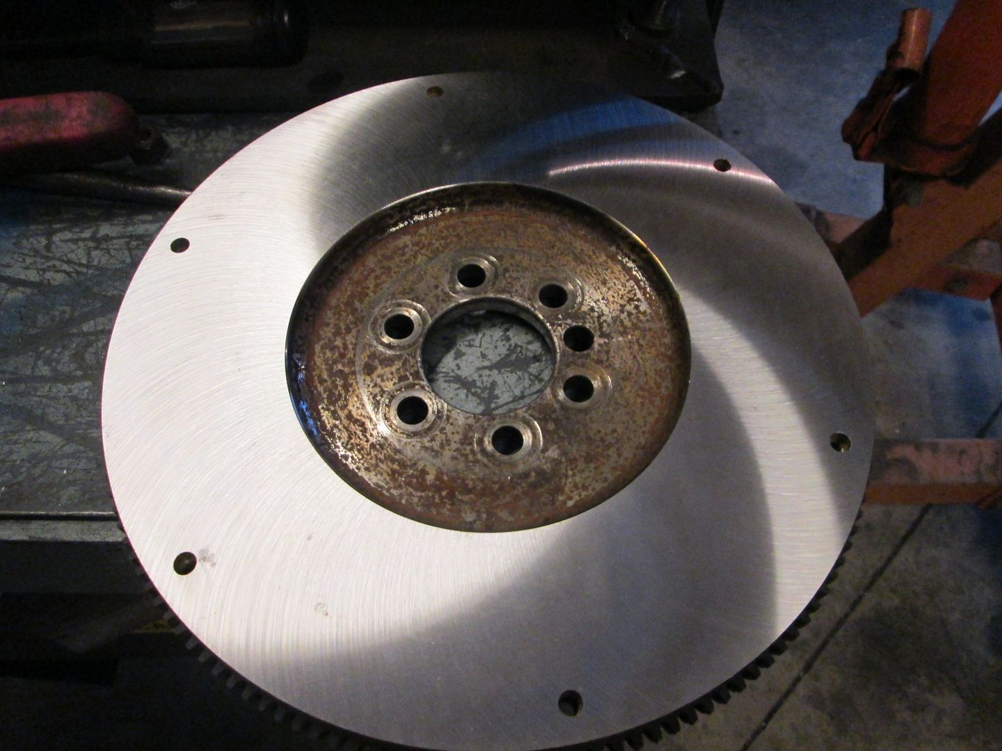
I removed the flywheel so it can be resurface (new Clutch is still MIA). The original Archie flywheel weighs around 29 lbs and I was curious as to how much this one weighs after it was modified for the 142 tooth ring gear... 23lbs 7oz:
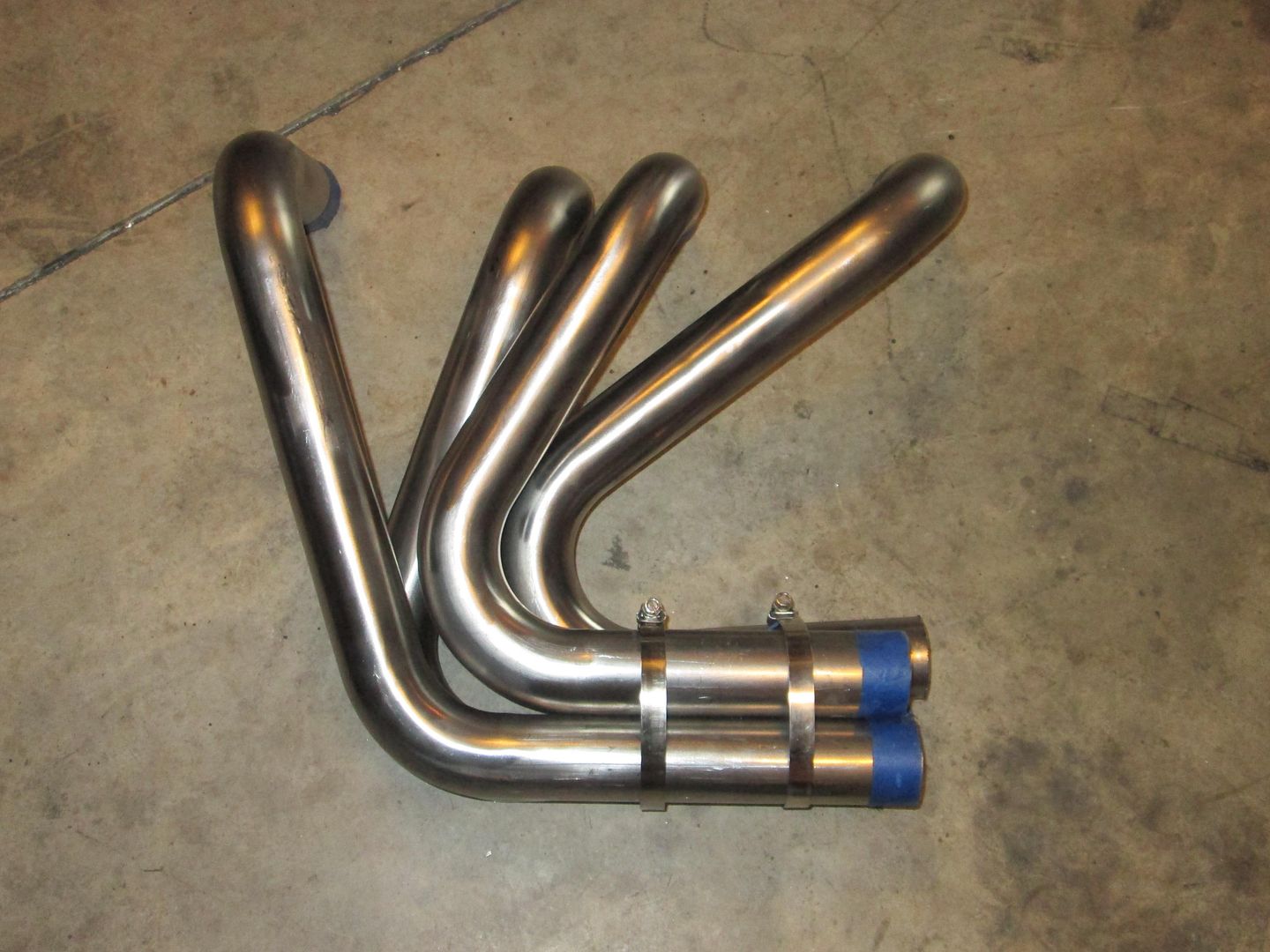
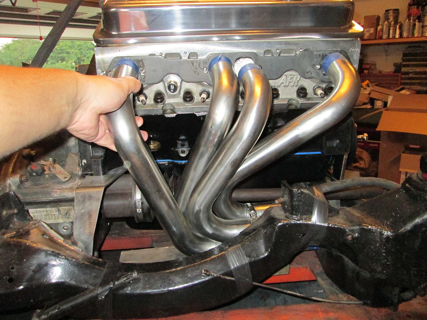
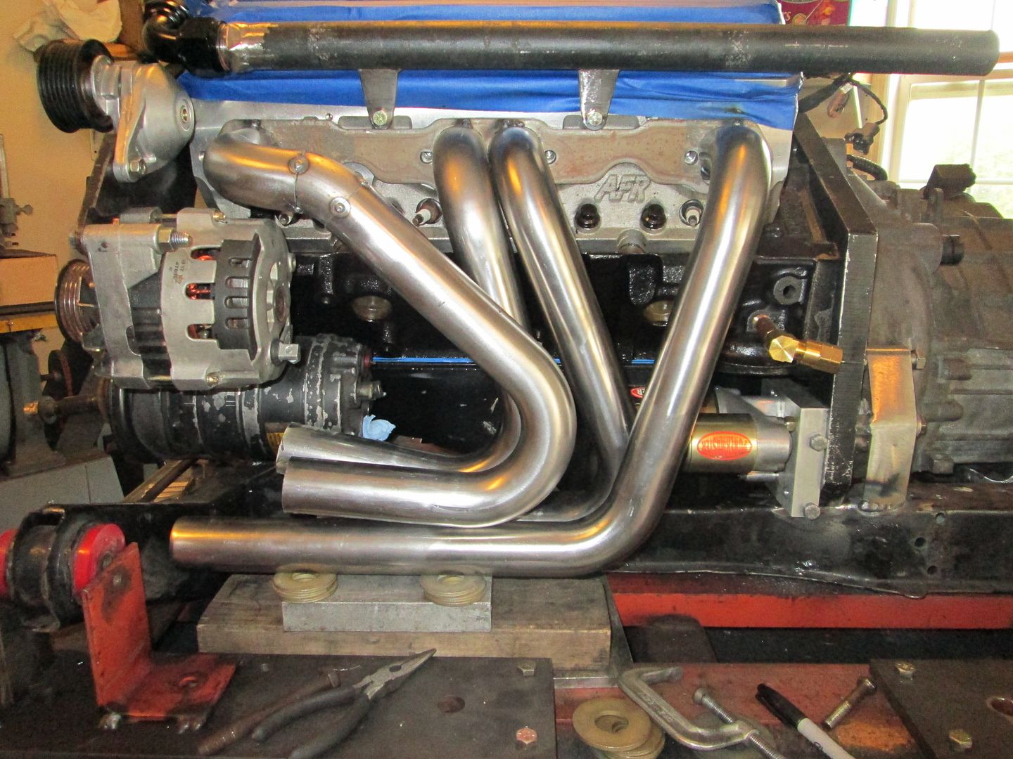
Put the engine/transmission on the cradle again so I can start mocking up the exhaust, the rest of the coolant crossover pipe and ECM mounting. Here is a very rough mockup of the exhaust I am hoping will work (1 3/4" primaries). The collector to 90 degree bend will be challenging and I might need to notch the rear crossmember some for additional clearance. The other side will be a mirror image so the tube on cylinder #1 should clear the alternator:
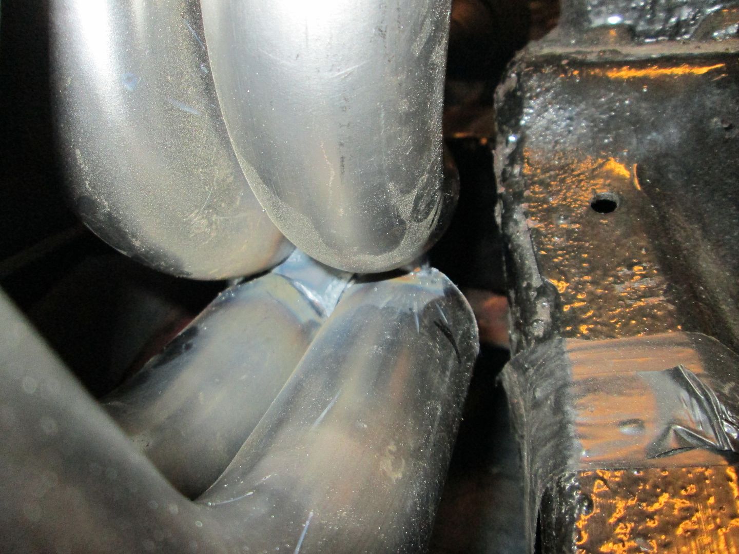
Spent about 4 hrs on the rear header... things are quite tight on this this. So lots of testing fit, remove, grind/cut, test fit... Here is the current state, the primaries are heavy tacked (3/4" bead top and bottom) at the flange and welded together at the collector, but the collector still needs to be welded in place.
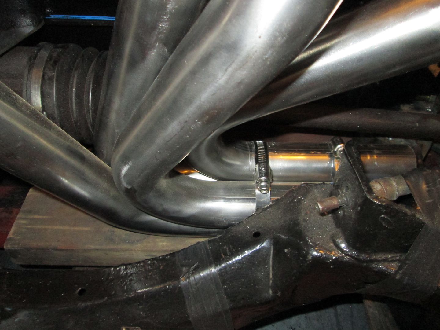
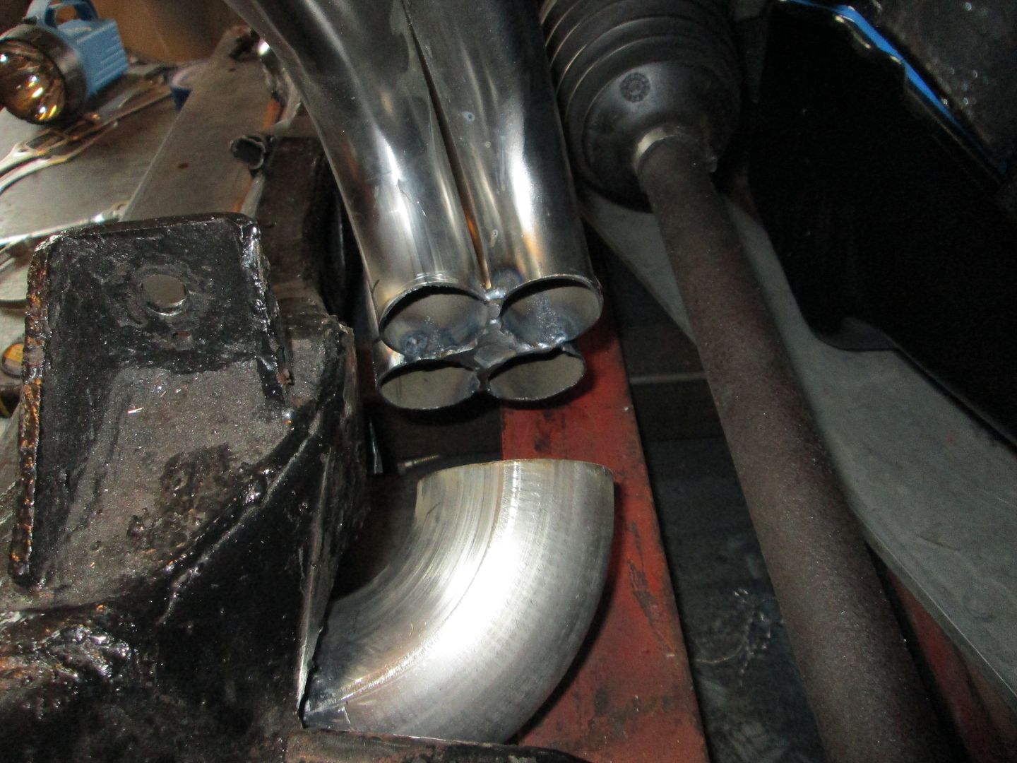
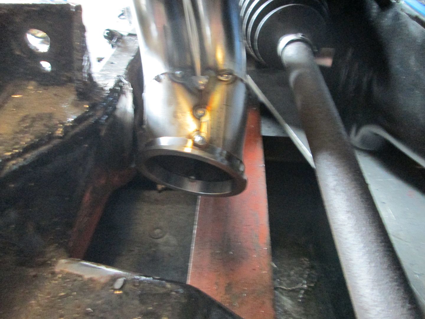
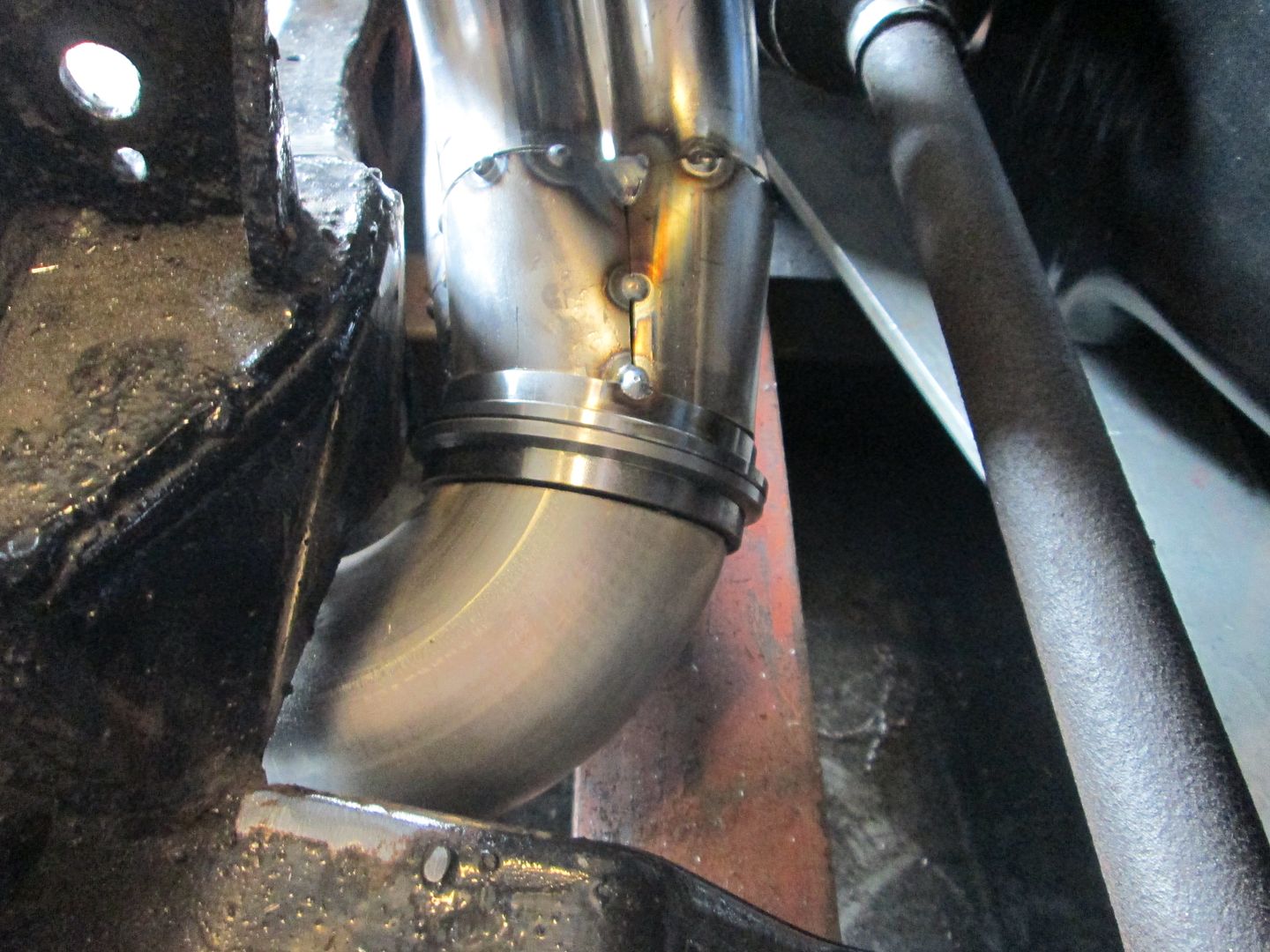
Here is the 3" exhaust elbow and the collector will be between these two:
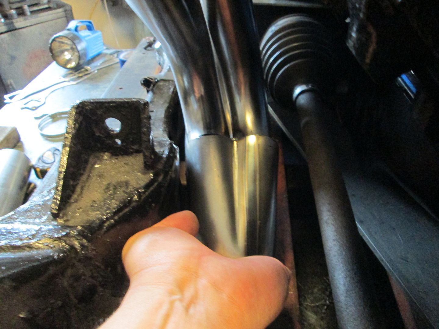
Here the collector is just sitting it place. I did cut the ends of the tube at a slight angle to help the collector angle down to the opening in the cradle:
Here is a pic of the surfaced flywheel. I am going to swap out the ring gear as it has some damage from some previous starter alignment issues:
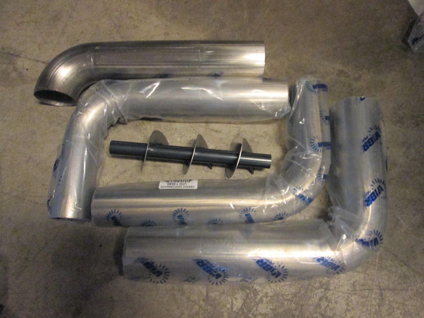
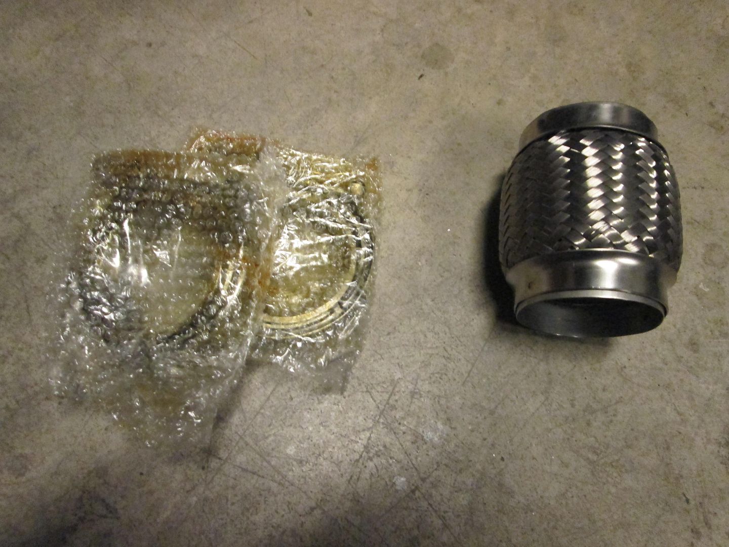
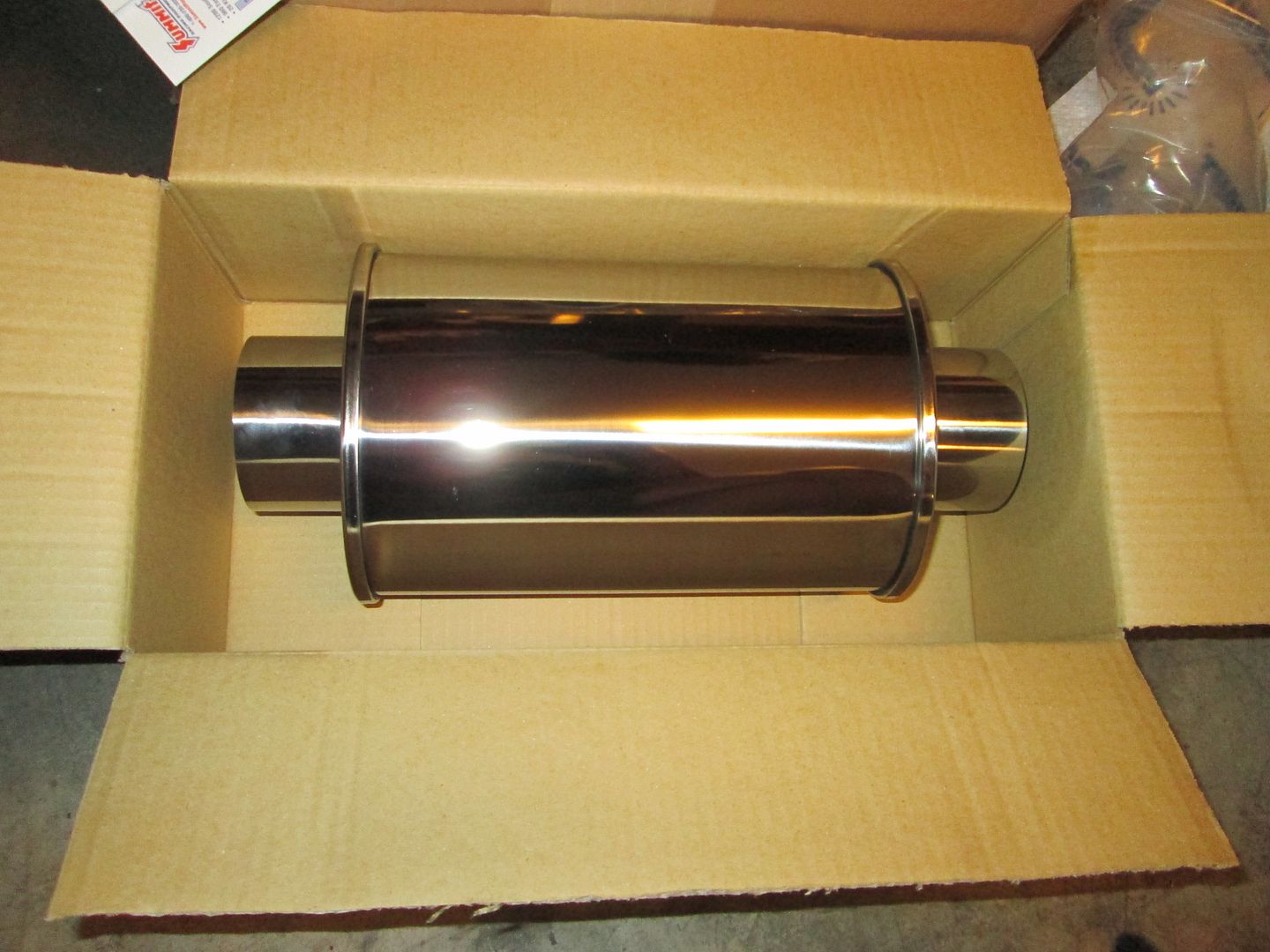
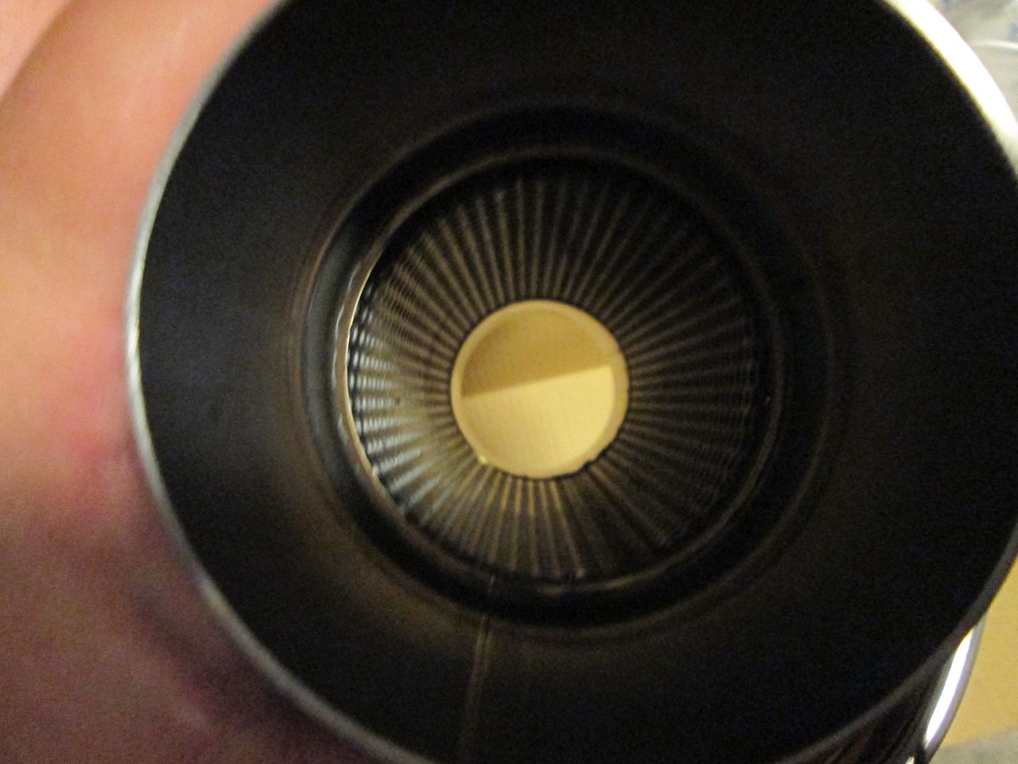
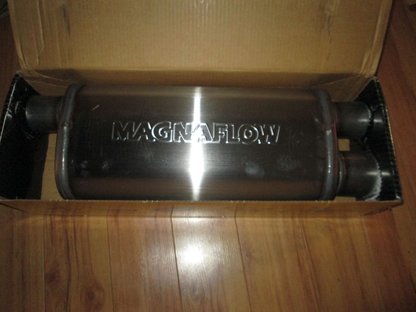
This car has the trunk removed below the shelf, so it has lots of room for the exhaust. Vince has asked for it to be rather quiet, so I am doing something different. 3" pipe from collectors w/ expansion joint on the front, Y'd into a single 3" pipe, then past the rear cradle cross-memeber turn 90 to go vertical, then turn 90 to the side, into a Vibrant Performance Ultra Quiet resonator, then 180 loop around to enter the Magnaflow cross flow muffler, then 2 1/2" pipes to whatever the tips are going to be. I am hoping the resonator in front of the muffler will make this car much quieter than all my previous V8 builds, but if it still needs to be toned down some, I will install the auger muffler insert into the resonator. Everything post headers will be stainless steel. The headers will be ceramic coated. Here are pics of the components:
I haven't even thought about tips.. as you saw with the last setup, the pipe just "ended" after a short extension from the mufflers to get to where the tips should have been. Off to Summit Racing I go!!
Check out these Gibson tips. The one in the pic is flat black, but they also come in polished stainless. http://www.gibsonperformance.com/dev/index.php I used to have a pair of them. Just didn't have a car to put them on. (I always thought they'd be perfect for the GT cutouts. Not so much for a Formula.)
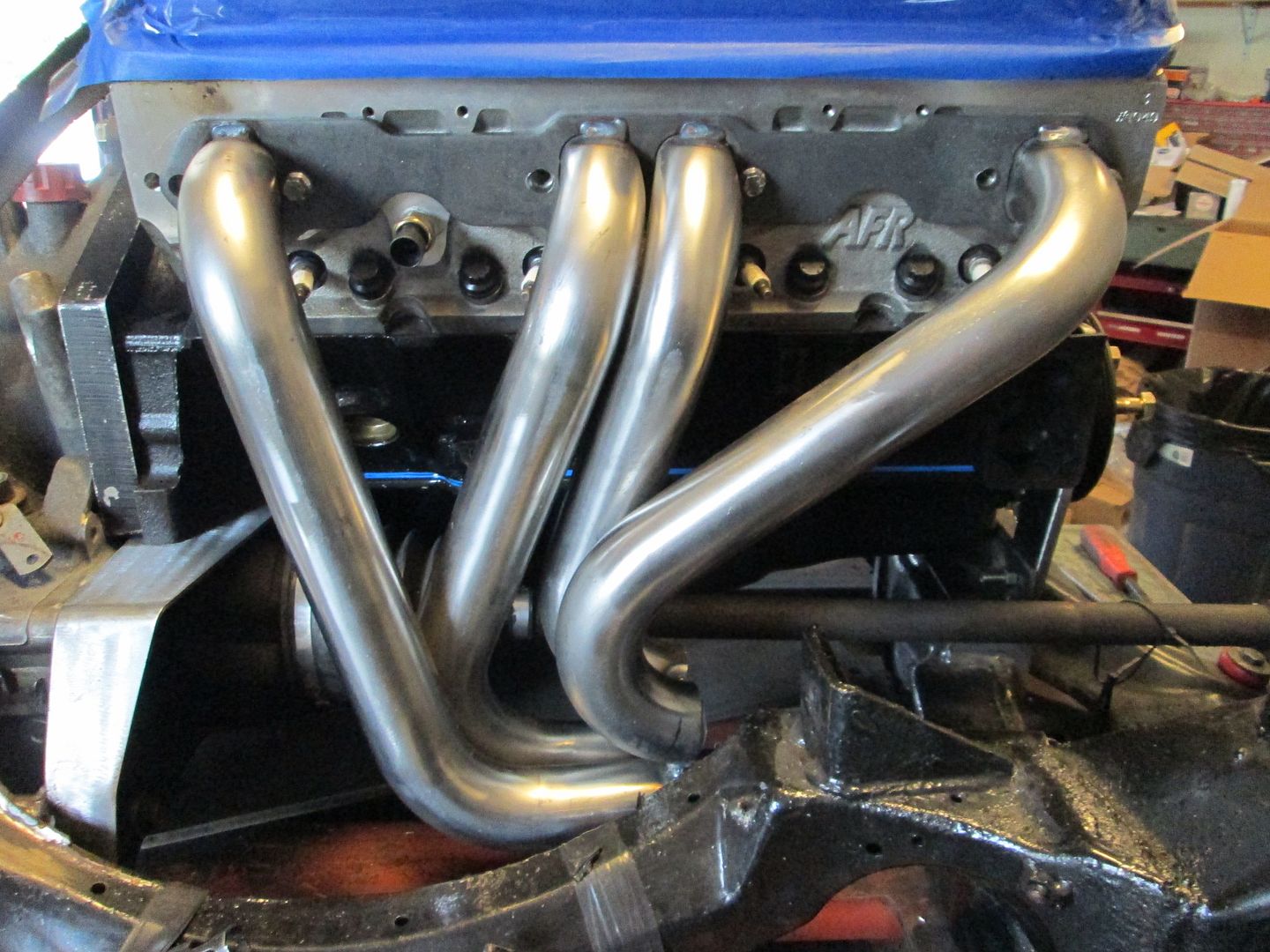
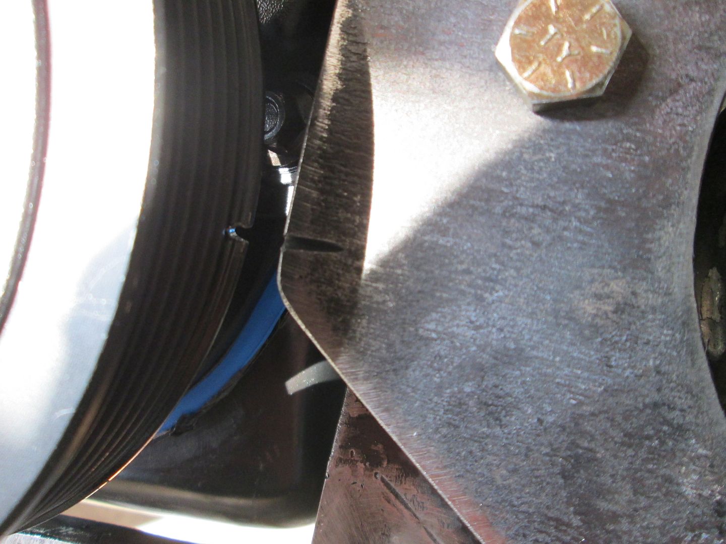
The front header is rough mocked up, still need to finish trim/form the primaries to the flange and then work on the collector. Notice I did have to mod the #1 primary for alternator (used a bend from some other 1 3/4" tubing I had on the shelf).
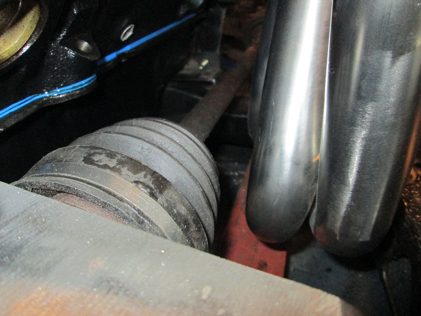
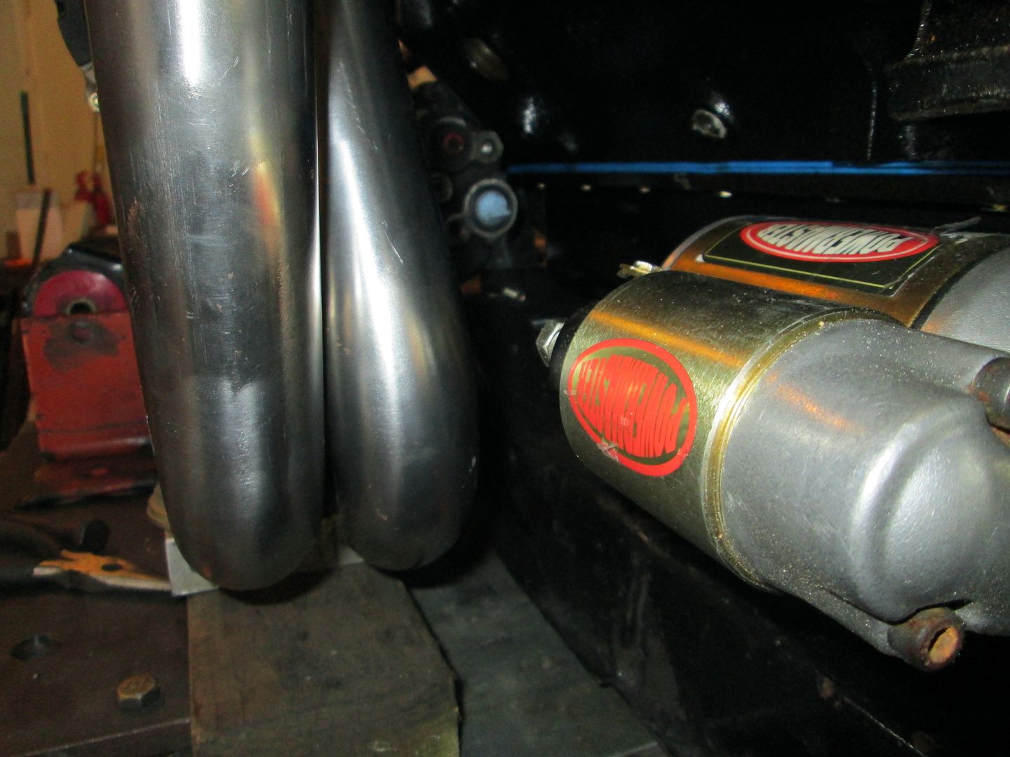
Clearance to the starter (there will be a heat shield to keep the starter cool):
Yeah, his work is amazing. For a while I was bugging him with different questions, making sure I had the right parts, wasn't overlooking things, then half-jokingly asked him if he'd be willing to do the work - was totally thrilled that he said he would. It's like getting on that Overhaulin' show... only better (no sudden paint changes that I might not like, but can't really dispute because hey... I'm on TV! lol)
There are only two or three people on this Forum (or not on this Forum, for that matter) who I would trust to undertake a project of this magnitude, and feel totally comfortable about the outcome.
Paul is at the very top of this list.
[This message has been edited by Raydar (edited 10-07-2013).]
This other one is really strange, reading it sounds functional and neat, but then you go "What happens when it's "intercooler" becomes heat saturated, just like a real intercooler? I figured at that point, it stops working as intended. Am I wrong? - http://www.summitracing.com.../bor-20213/overview/
The first one looks nice....but I question using a steel tip when the rest of the exhaust system will be stainless. But, I am far from being an exhaust expert...so I might be getting too picky there.
Second one...even when saturated with heat, there is still air flowing through to help cool. Again, I am not an exhaust expert, so I can't really comment on whether that feature would be worth the money. I can see potential advantages to keeping heat away from the bumper though.
Third one. Personal preference....I am not a fan of the square ones.
What about the C6 tips I see floating around here regularly? I think this is an ideal use for them.
The GT megaphone tips are 14 1/2" in length including the 90 on the exhaust pipe. The 2 1/2" pipe needs 4 inches for the 90 degree bend, so you are looking for a tip that is about 10 1/2" in length or less, unless you want to ends to stick out further than stock.


 Topic Closed


 But why quote the whole long post, just to say it?
  It kinda muddies the thread when a post with 25-30 pictures is quoted in full...