Gasket/seal set ($72 shipped) Individual Injector upgrade for the poppets ($115 shipped - 35K miles on them) 153 tooth 86+ aluminum flywheel McLeod ($220 shipped - new on clearance) 5/16" thick header flanges for 1 3/4" primaries ($49 shipped)
Other items I am waiting for quotes or further investigation: 3/8 x 12 x 13 aluminum plate (quote requested) Rod and Main Bearings - need to check clearances to see if I need these Clutch/pressure plate (might just use the ford 3.0 clutch disk with my Spec stage 2 pressure plate).
Been working on finishing the axles for the F40 in my SBC/F40 thread...
I would like to have this engine upgrade/F40 install done before the Fiero Factory swap meet... gotta get crackin...
IP: Logged
04:23 PM
Isolde Member
Posts: 2504 From: North Logan, Utah, USA Registered: May 2008
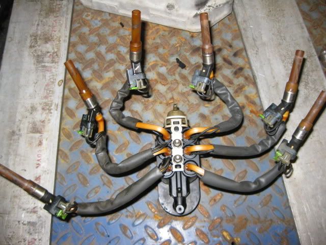
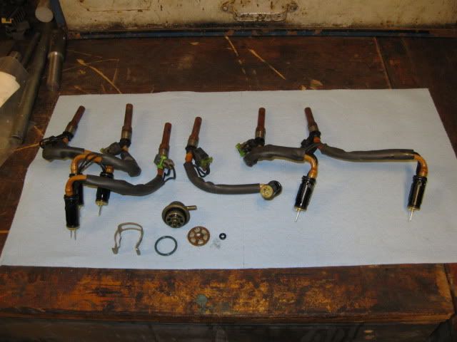
Parts are starting to show up. The spider with the individual injectors showed up today... so of course I had to take it apart:
The large body/connector harness will not fit within the CPI intake, so I am planning to make an aluminum distribution block that will fit where the old CPI injector sat in the middle of the intake. There will be some nipple for the fuel lines to the injectors and I would like to reuse the pressure regulator if possible.
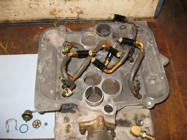
After dinner, I need to drill the poppet valve holes in the CPI intake so the new Injectors will slide into place.
IP: Logged
04:24 PM
fieroguru Member
Posts: 12128 From: Champaign, IL Registered: Aug 2003
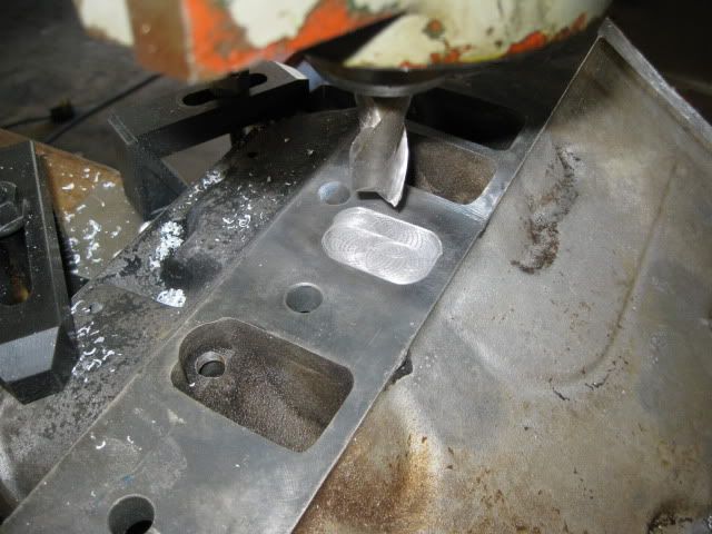
A quick hit with an 11/32 drill bit and the injectors would slide into place:
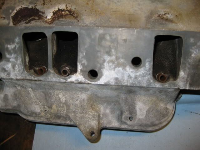
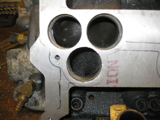
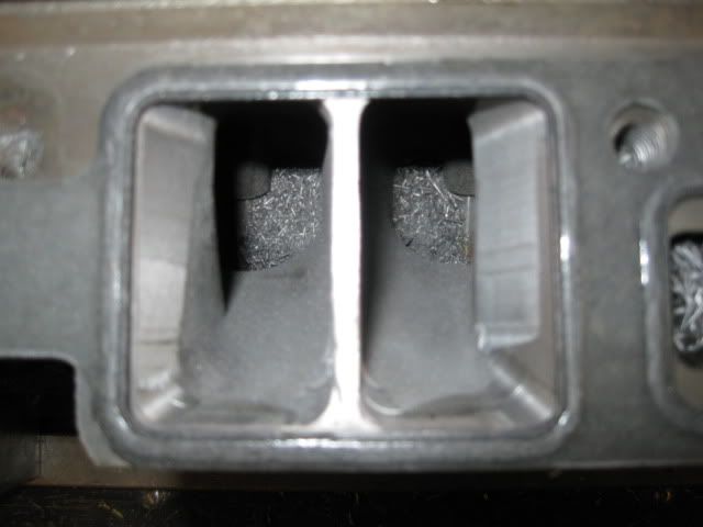
Here are a couple of port shapes from the Vortec Heads (top) and the CPI Intake (bottom). I have some die grinder bits coming to help massage the ports as the intake and heads meet. The vortec heads need to be just a little bit wider and the CPI intake needs to have material removed from the top around the injector outlet.
IP: Logged
06:39 PM
Mar 18th, 2010
fieroguru Member
Posts: 12128 From: Champaign, IL Registered: Aug 2003
I am confused. Do you need to make a change to the exhaust with the intake swap or M/T or is this just a upgrade?
It gets complicated... The current adapter plate used on the 4.3/4T60 rotates the transmission differential downward relative to the engine (done to help reduce the amount of the OEM starter pad needed to be cut off). So when I installed it originally, I split the difference and roated the engine slightly forward. The exhaust and engine mounts were all made for this angled install and would require reworking.
Since this 4.3 swap is really an R&D platform for my tubular cradle, F40 swap parts and F40 specific adapter plate...the exhaust will not work since the tubular cradle needs an over the tranny style exaust (no means for it to run under the crossmembers), so I am making some manifolds similar to the stock fiero, but with 1 3/4" tube and a nice gradual bends into the common tube (which will taper from 1 3/4 at the 1st port to 2 1/2 after the last one).
Then, since I am not using the old 4.3 engine, 4T60 tranny, axles, manifolds/complete exhaust, cradle, adapter kit, accessory drive, intake/harness/ecm... I will sell off the install as a package... but the engine & tranny would both benefit from a rebuild.
Some days I just take the longest path to my destination. With the tubular cradle, aluminum flywheel and F40 I am trying to get as close as possible to the 2.8/5speed weight. I will still probably be about 50 lbs heavy, but moving the battery to the front would help as well.
[This message has been edited by fieroguru (edited 03-20-2010).]
IP: Logged
08:53 AM
Isolde Member
Posts: 2504 From: North Logan, Utah, USA Registered: May 2008
Brodix does make aluminum heads for the 4.3, that'd save 30 pounds. But for this engine, 1.625" primaries about 38" long would be ideal. Now, where's the little emoticon of the yellow smiley face eating popcorn?
Haven't done anything today project wise... the guy from Iowa was here to pick up the Index mill from 7:30 to 9:30. Then I fixed an exhaust rattle on the wife's maxima, then replaced the brake line on the truck that blew out last thursday. Now the wife is getting a hair cut... and I am keeping the girls out of trouble.
I am hoping to finish up the adapter plate for this engine this afternoon and get to work on engine placement/mounts (with the SBC... so so there is room later on).
IP: Logged
01:09 PM
PFF
System Bot
fieroguru Member
Posts: 12128 From: Champaign, IL Registered: Aug 2003
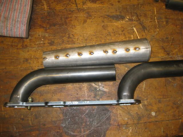
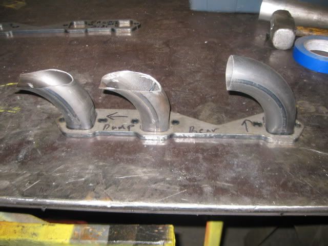
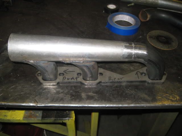
The adapter pics are in my SBC/F40 thread, but here is one of the manifolds I was just playing around with today. The aluminuzed tube was pie cut to be 1 3/4" on one side and 2 1/2" on the other. Then some hose clamps to close it up, place it on a 1 1/4" piece of pipe to hammer the seam smooth and then tack it together.
The 90's are 1 3/4" and I will probably make them about 1" longer where I square them up to attach to the flange... Then as soon as the front tube clears the head, there will be a 90 degree bend for the tube to follow the top of the adapter plate over the tranny and meet up with the rear one.
IP: Logged
06:29 PM
Mar 22nd, 2010
fieroguru Member
Posts: 12128 From: Champaign, IL Registered: Aug 2003
The 3/8 x 13 x 12" aluminum plate for making the adapter plate/spacer to allow the upper intake to be flipped came into today... all I got around to doing was taking it to the basement.
IP: Logged
07:22 PM
Mar 23rd, 2010
fieroguru Member
Posts: 12128 From: Champaign, IL Registered: Aug 2003
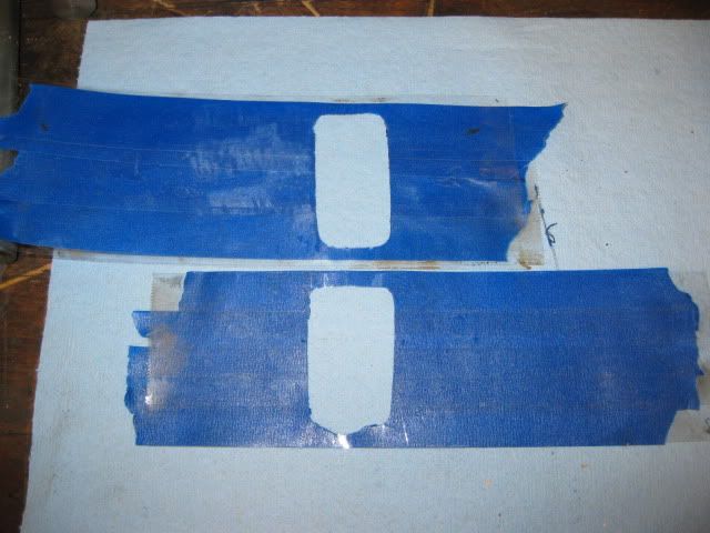
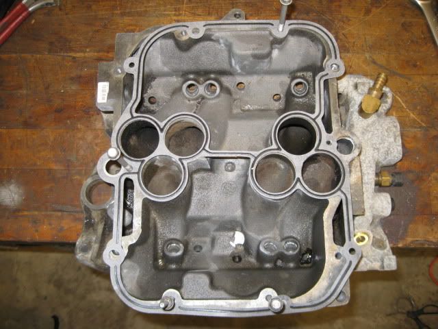
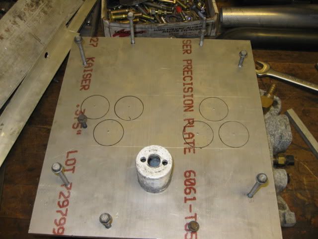
Started working on the adapter plate today... First thing was to check for any bolts that have commone holes, so I flipped the gasket and found that 4 of the holes line back up with the intake flipped.
Then it was a matter of using my threaded center punches to locate all the theaded hole locations in the lower intake (all but 1 that is broke off... I will need to fix this eventually). I went ahead and circled the general port locations from the gaskets, but those are far from acurate.
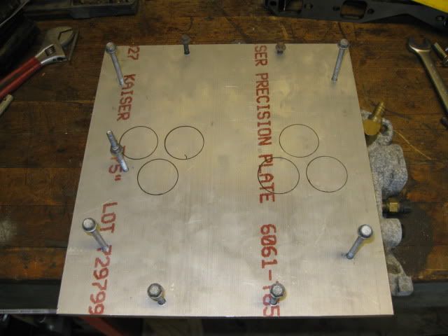
To locate the locations of the center of the runners, I started with the bolts installed and then found the proper combination of shims to have a edge flush with the edge of the runners. Then put the top back on reinstalled the proper combination of shims and scribed the edge of the runner...
Repeated this more times than I care to remember, but ended up with the true centers of the ports - center punched. Maybe on Wednesday I will be able to hole saw the runner holes.
IP: Logged
07:42 PM
Mar 24th, 2010
fieroguru Member
Posts: 12128 From: Champaign, IL Registered: Aug 2003
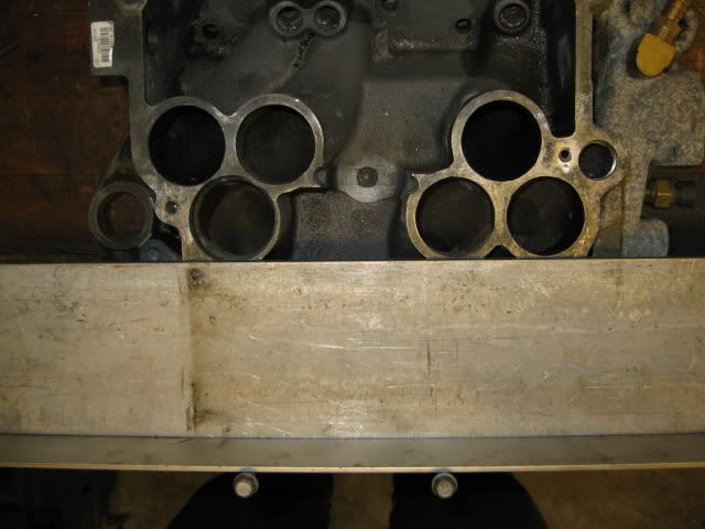
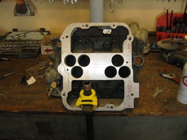
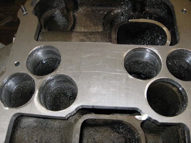
The holes came out pretty decent. The holes are slightly larger in diameter than the upper and lower intakes, so I can help smooth out the transition by enlarging the last 1/2" of the runners. On lower intake:
On upper intake:
With the 2 put together and 3 bolts installed:
IP: Logged
07:06 PM
Mar 27th, 2010
fieroguru Member
Posts: 12128 From: Champaign, IL Registered: Aug 2003
Only got a couple of hrs to work in the garage today... but countersunk the needed bolts for the intake adapter plate. Then traced the outline of the upper intake and the inside shape of the gasket to have some guide lines while milling off the excess material. I plan to go over the outside surface with a flapper disk to smooth out the curved faces.
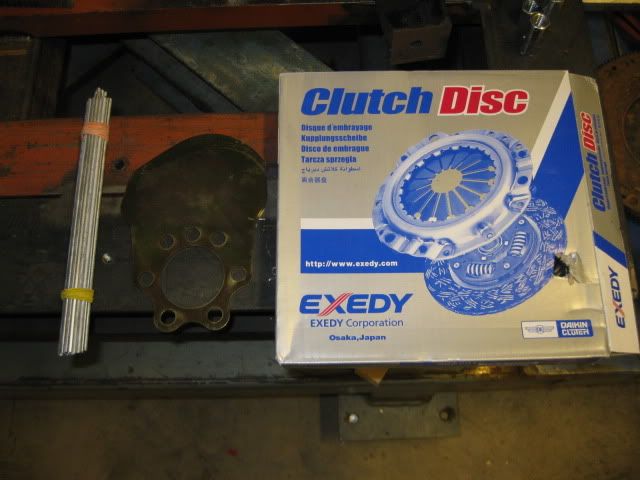
I scored a brand new clutch disk for $25 on ebay that will work for the F40 and I will be using my Spec Stage 2+ pressure plate. Found a vendor for a crank mounted balance plate for the 86+ SBC since the current bolt on weight on my flywheel is right where the new ring gear needs to be. Also, purchased some aluminum brazing rods to play around with.
I would like to have this intake adapter plate done this weekend, so Sunday will be busy!
IP: Logged
06:58 PM
Isolde Member
Posts: 2504 From: North Logan, Utah, USA Registered: May 2008
Who is the vendor for your weighted pulley? Will the weighted pulley serve the same purpose as the weighted flywheel? I too have a Nissan ring gear and the Chevy flywheel balance is in the way when fitting the ring gear.
Ken
------------------ '88 Formula V6 '88 GT TPI V8
IP: Logged
01:34 AM
fieroguru Member
Posts: 12128 From: Champaign, IL Registered: Aug 2003
Who is the vendor for your weighted pulley? Will the weighted pulley serve the same purpose as the weighted flywheel? I too have a Nissan ring gear and the Chevy flywheel balance is in the way when fitting the ring gear.
Ken
Yes, the balance plate takes the place of the bolt-on counter weight for the 86-96 SBC/LT1 family (make sure not to get the one for the 400/383 SBC) and it bolts to the crankshaft between the flange and the flywheel. Word of caution... if you are planning to use this with a Z-kit adapter (Street Dreams or others), you probably do not have the .100" of clearance that this plate needs unless you add spacers to the adapter plate to make up the difference (also, you probably do not have room to weld the original bolt on weight to the back side of the ring gear either due to the starter support). If need be, you could do the math to resize the original bolt on weight to move it about 1" closer to the crankshaft (you would need to add weight to it).
I got mine off ebay. Here are a couple of vendors who sell them:
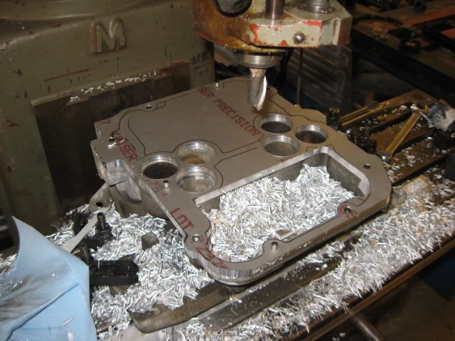
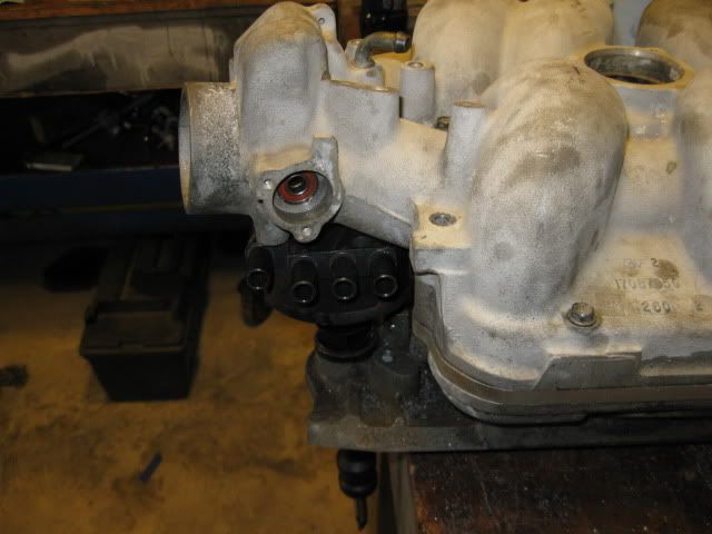
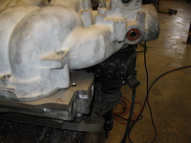
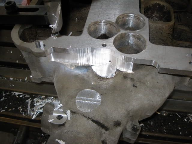
The adapter plate is nearing completion... I located, drilled and tapped the set of holes for the upper intake, then took the air grinder and smoothed the runners to the adapter plate.
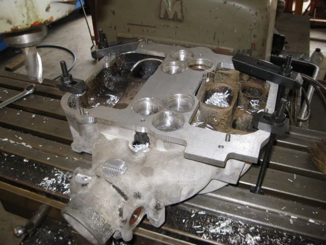
I noticed the main air inlets were partially blocked by the center portion of the adapter plate, so with it attached to the upper intake, bolted it down to the mill and removed some additional material to open up the air inlets. Also took this time to mill off the old EGR port and remove some additional material on the neck so the dist will clear.
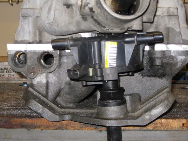
Here everthing is bolted back together and the dist clears! I will probably do alittle more clearancing on the intake side to provide more clearance for the dist and remove the last 1/2" of the adapter plate right above the fuel inlets so the plug wire will have more room.
IP: Logged
04:40 PM
Mar 30th, 2010
kennn Member
Posts: 272 From: Green Valley, AZ USA Registered: Apr 2006
Guru, thanks for the balance plate info. I do have the Zumalt set-up. I'm going to mate the 350 to the F40 utilizing a cut-down Chevy flex plate with the Nissan ring gear for the starter, a spacer, and then the flywheel/clutch assembly. It seems I could sandwich the plate balancer between the crank and flex plate or between the flex plate and the spacer.
Ken
------------------ '88 Formula V6 '88 GT TPI V8
IP: Logged
01:34 AM
PFF
System Bot
Apr 11th, 2010
fieroguru Member
Posts: 12128 From: Champaign, IL Registered: Aug 2003
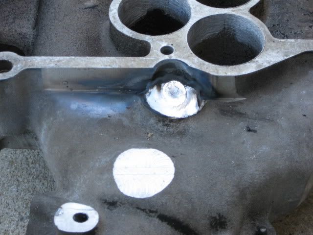
Did some aluminum welding to cap the unused EGR holes. Lots of cleaning, then cut some small pieces of 1/4" thick aluminum to fill the majority of the holes, then fire up the welder.
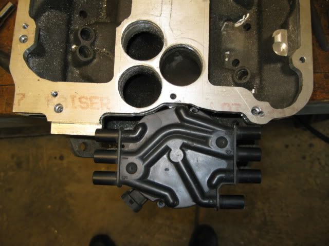
Then it was time for some mill work to smooth out the welds and make room for the dist:
Did some additional distributor clearancing on the adapter plate and lower intake as well:
And drilled/tapped the new EGR inlet:
I still need to drill a hole into the EGR passage that is cast into the lower intake (from the head port I welded shut to the area where the EGR valve bolts on) to allow it to vent into the lower intake housing.
IP: Logged
06:14 PM
Isolde Member
Posts: 2504 From: North Logan, Utah, USA Registered: May 2008
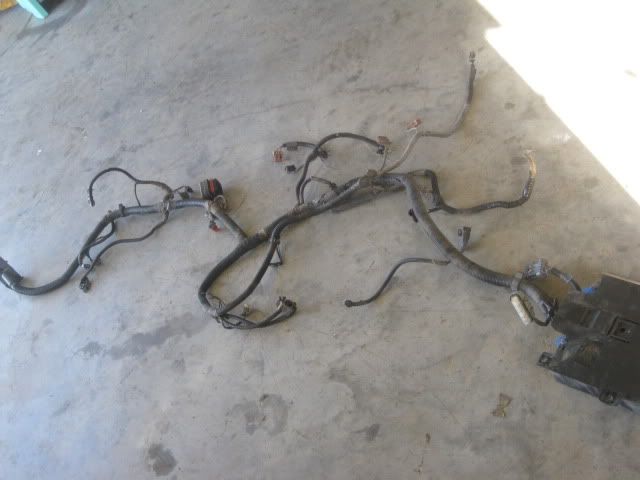
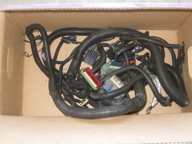
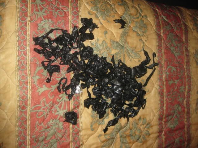
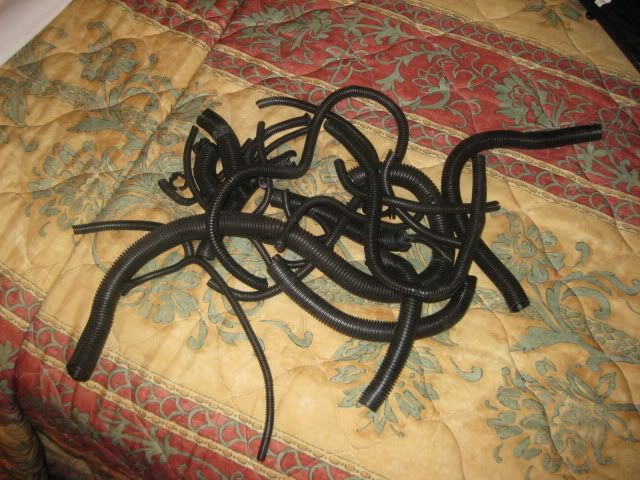
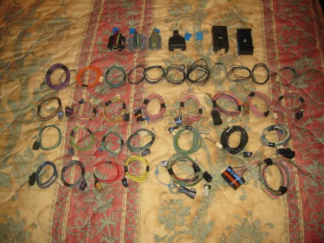
Work is going to have me living out of a hotel for the next couple of weeks, so I will be focusing my spare time on what I can do while in the hotel... tear down and label harnesses.
I will be taking the original engine harness from the 99 4.3/5speed as well as a brand new one (2000 4.3/5 speed) that I picked up on ebay for $50. Both harnesses will be opened up and all the individual sensor circuits seperated, labeled and coiled up for storage. Then when it comes time to build the harness, I can plug the connectors in where they go and route the wires where they will have the least amount of visual impact.
IP: Logged
06:06 PM
Apr 20th, 2010
fieroguru Member
Posts: 12128 From: Champaign, IL Registered: Aug 2003
I didn't know that new harnesses could be found on e-bay. So after reading this, I searched, but got lost. Please post a link? My '96 4.3 / auto harness is heavily damaged, and PainlessWiring wants over $700. Thanks.
IP: Logged
12:48 AM
fieroguru Member
Posts: 12128 From: Champaign, IL Registered: Aug 2003
I didn't know that new harnesses could be found on e-bay. So after reading this, I searched, but got lost. Please post a link? My '96 4.3 / auto harness is heavily damaged, and PainlessWiring wants over $700. Thanks.
You can buy almost anything on ebay if you check often enough. Just search for "4.3 harness" and "4.3L harness" and you will get quite a few used ones and occasionally you will find a new one (like the guy purchased it for a project that never happened and is selling off the aquired parts). Some will be expensive and some can be had dirt cheap depending on the sellers motivation to get rid of it.
IP: Logged
12:03 PM
Apr 25th, 2010
fieroguru Member
Posts: 12128 From: Champaign, IL Registered: Aug 2003
Home for the weekend and getting ready to go back out of town. A metal fabrication contractor has agreed to let me use his place to do some after work activities. I wanted to take the whole cradle/engine/tranny but I need to take a couple of willet printers to the plant so my truck is already pretty full.
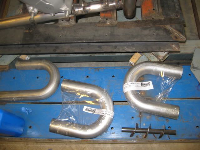
I will be taking the tubing and flanges to make the exhaust manifolds as my after work activity.
IP: Logged
05:05 PM
Apr 27th, 2010
fieroguru Member
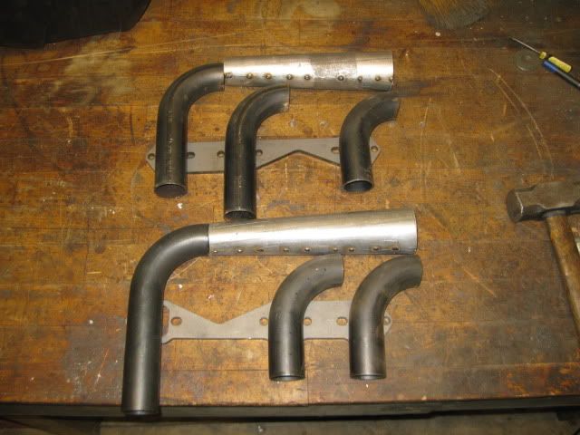
Posts: 12128 From: Champaign, IL Registered: Aug 2003
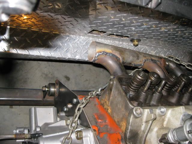
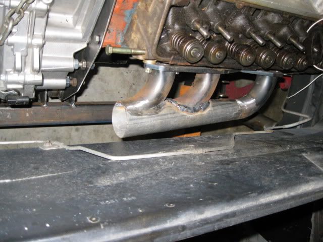
I was able to confirm these manifolds will clear everything in the chassis. The front manifold has more than 1" clearance all the way around and the rear one will have about 1/2" clearance to the trunk (notice the 1/4" spacers... there is a plug in the SBC heads and it kept me from completely bolting the rear manifold to the head.
IP: Logged
02:38 PM
May 11th, 2010
fieroguru Member
Posts: 12128 From: Champaign, IL Registered: Aug 2003
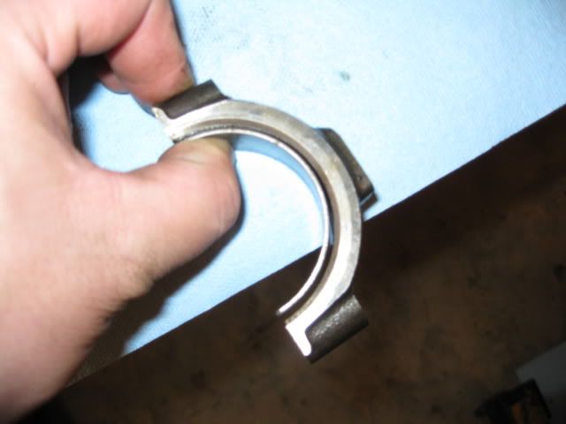
I tore into the 99 4.3 today to check for the source of the hot rattle... all the mains were in good shape, but the rod bearings on #3 & #4 looked like this:
They were slightly scored and appear to have been hot, but did not spin. They should not pull away from the cap like that. I am going to polish the crank and see if I need to get a replacement one....
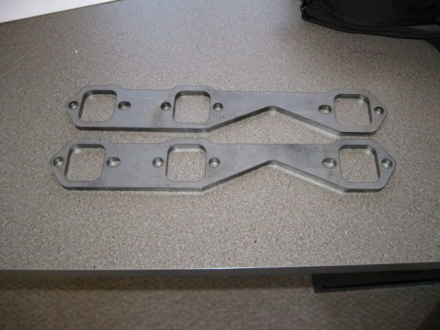
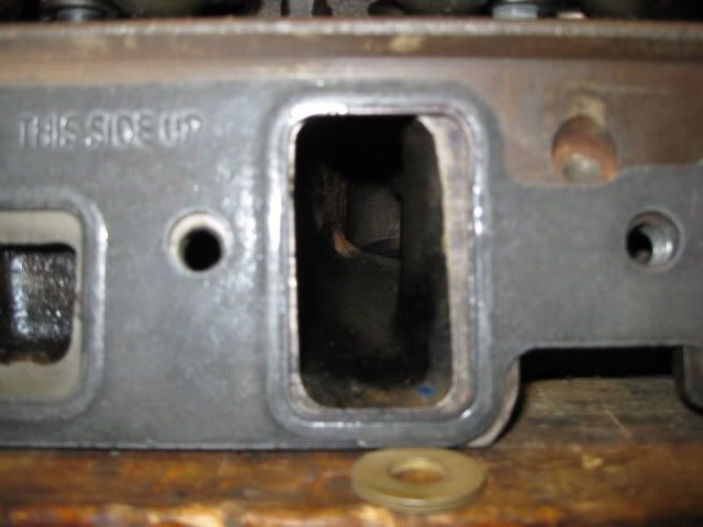
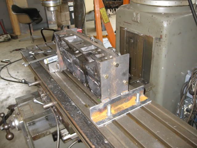
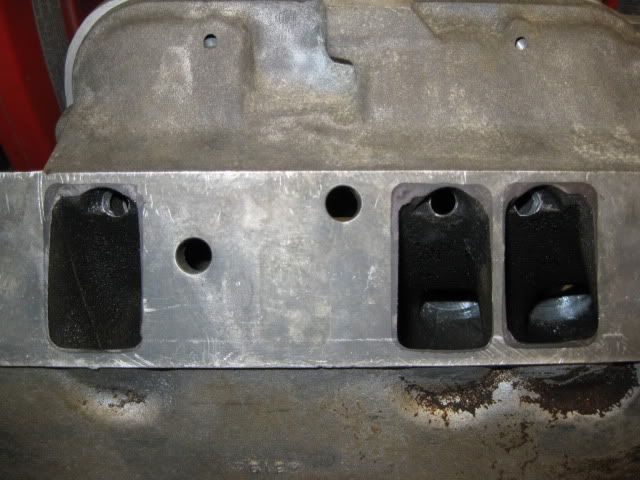
Then I decided it was time to work on port matching the heads to the intake. Since the heads are 96+ and the intake is a 94, there is a faily significant amount of material to remove for a smooth transition.
Here is the 94 gasket on the Vortec heads:
Decided to use the mill to remove the vast majority of the material... so I had to make a precision fixture to properly position, align and elevate the heads on the mill table. I made some side plates that bolt to the side of the heads, then clamped the head down to the tabled via the intake face. Then milled the side plates down so they are level with each other, parrallel with the table and then machined some tabs on the side plates to set inside the T-slots to make the intake pattern parrallel with the t-slots. Some angle welded to the side and a few holes for the hold downs... and I have a head fixture for the 4.3/SBC.
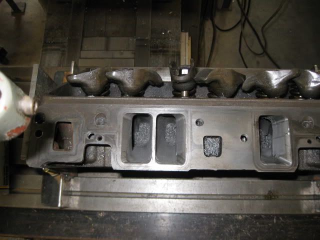
For the material removal, on the tapered surfaces I angled the head to 25 degrees (both to the side and nose down - at different times). This allowed the majoity of the material to be removed and tapered back into the cast surface within about 1" of the entrance. This should smooth up the transition, but not really change the flow of the intake ports. I still have some file work to smooth then out a little more but the mill worked pretty good.
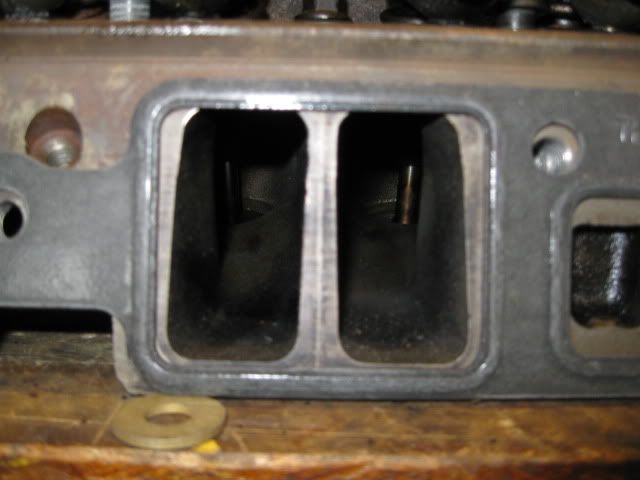
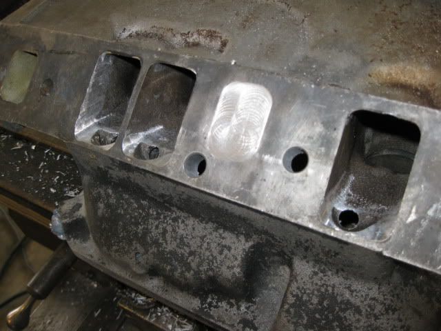
Here are some before/afters:
On Wednesday I plan to get the other head finished.
Here I outlined the inside surface of the gaskets on the intake manifold. It is a much closer match and I will probably just use the die grinder for it.
[This message has been edited by fieroguru (edited 05-11-2010).]
IP: Logged
06:14 PM
Pete Matos Member
Posts: 2291 From: Port St. Lucie, Florida Registered: Jan 2010
Like what you are doing here.... I have the vortec V6 4.3 liter motor in my Astro van, have had quite a few and they are GREAT engines. Even stock in my van it makes that thing haul ass pretty good, and it is pretty heavy and just slightly more aerodynamic than a brick wall. In a fiero, forgetaboutit!!! Especially with your custom exhaust, port matching, maybe a cam and heads and you should have some serious power in that little car. Really like the had fixture, good work and interesting machining operations. That intake spacer I assume is to reverse the intake manifold to work in the fiero right??!! keep up the good work... peace
Pete
IP: Logged
07:21 PM
Isolde Member
Posts: 2504 From: North Logan, Utah, USA Registered: May 2008
Would've been better to add epoxy to the intake manifold. I did this to some Vortec 350 heads back when I has access to a new SuperFlow 1020, it really screwed up the charge motion, flow really suffered more than it should have. Best to stop now and find another pair of heads.
IP: Logged
08:04 PM
May 12th, 2010
fieroguru Member
Posts: 12128 From: Champaign, IL Registered: Aug 2003
Guess I will just have to wait till it is running to see how bad that head is. On the other side, I went to 35 degrees for the side cuts and it greatly reduced the material removed. Once up and running the ECM will let me know is one bank is flowing less air than the other... If it is a significant difference, then I will swap out that head... and probably upgrade camshafts and install a set of roller rockers and a better clutch...
It only took 20 minutes to do the 2nd head.. partially because I took off a bunch less, and partially since I had the learning curve on the 2nd one.
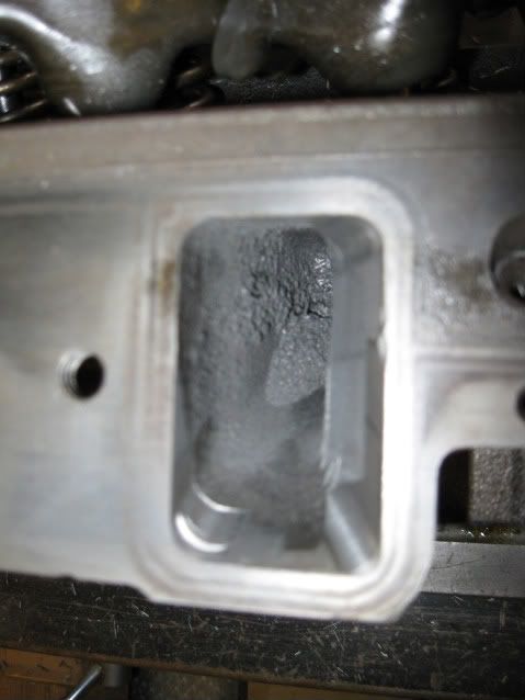
Here are the intake ports cleaned up:
I probably have about 8 hrs dedicated to keeping the EGR valve functional... but I am now done with all the modifications.
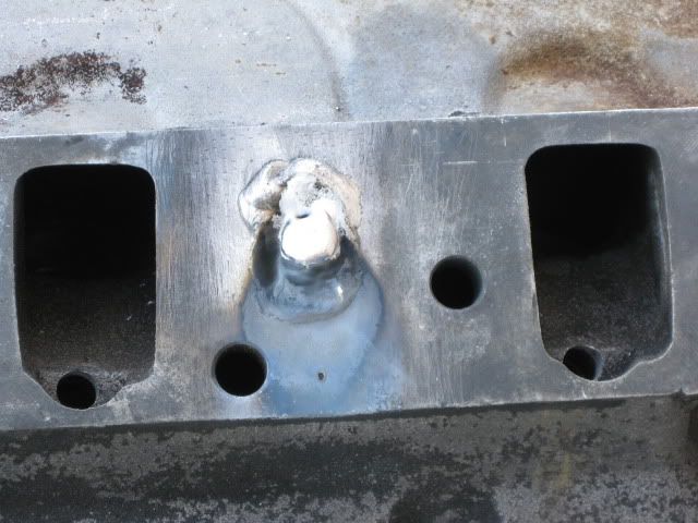
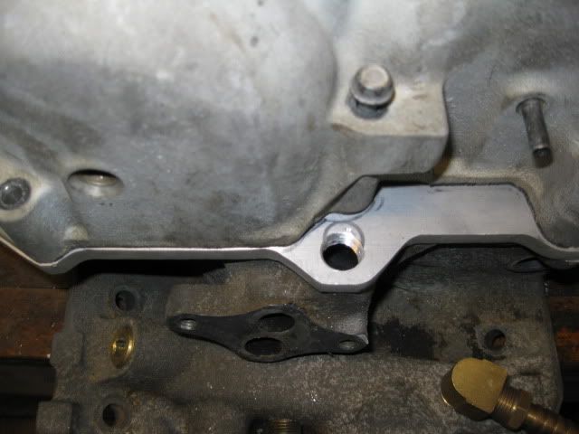
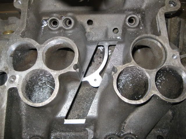
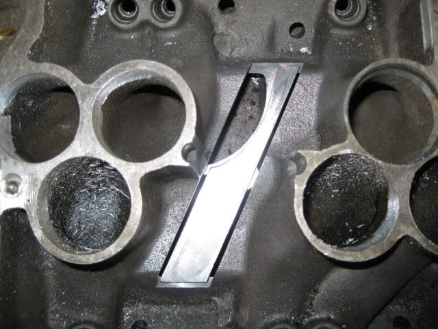
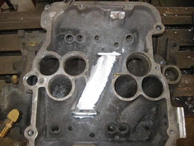
Step 1 - mill down the inside of the intake to make the base of the NEW egr passage... Intake didn't have as much material in this area I thought it did... that's why I learned to weld aluminum...
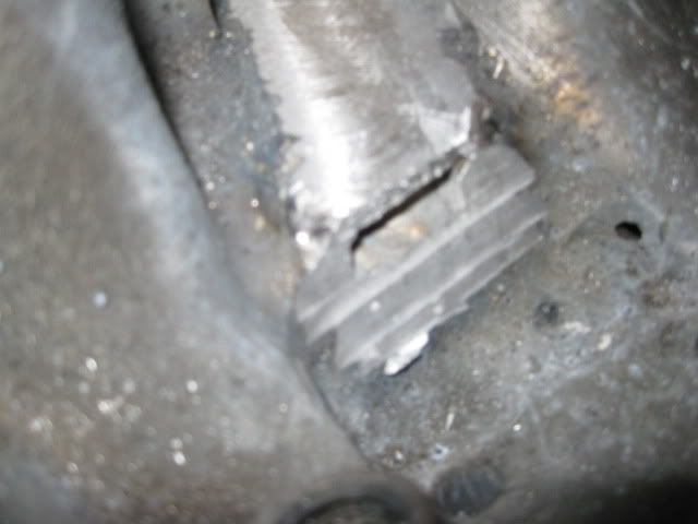
To the left of the curved piece is the stock EGR passage. Cut some 1/4" aluminum bar so I can weld it in along the EGR seam as well as along the sides of the intake.
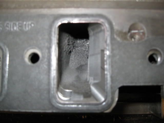
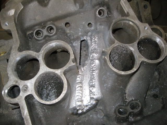
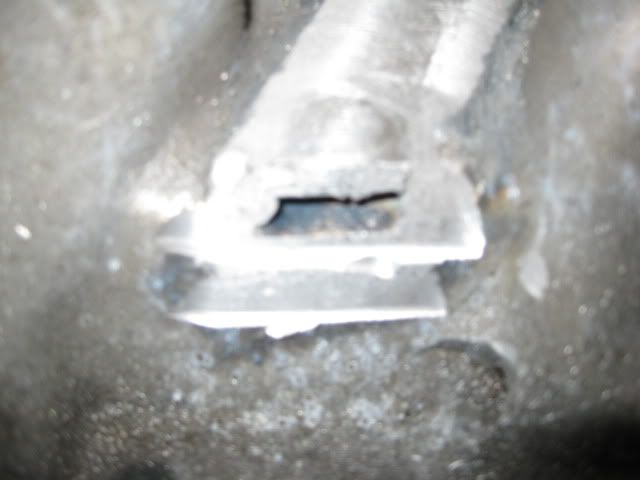
Then cut a small piece to weld in and cap up the EGR port, mill everything back down to make it smooth again and drill the new hole into the original EGR passage.
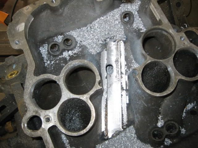
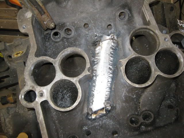
Cut another piece of 1x1/4 aluminum for the top cap, weld it in and then mill it down flat. Now there are two outlets for the EGR.
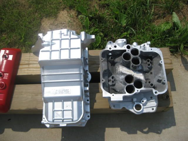
Spent about an hour cleaning and scrubbing the grime buildup on the oil pan and timing cover.
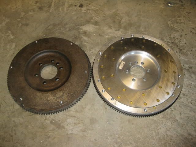
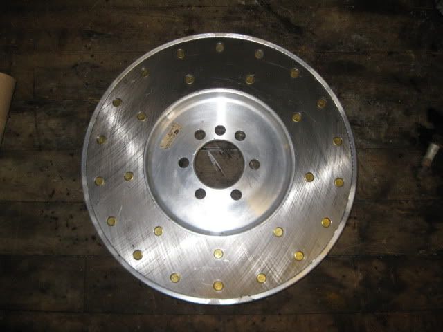
Last project for the day was to finish turning down the aluminum flywheel so it would fit within the F40. On Thursday I will drill/tap it for the pressure plate bolts.
IP: Logged
05:22 PM
May 29th, 2010
fieroguru Member
Posts: 12128 From: Champaign, IL Registered: Aug 2003
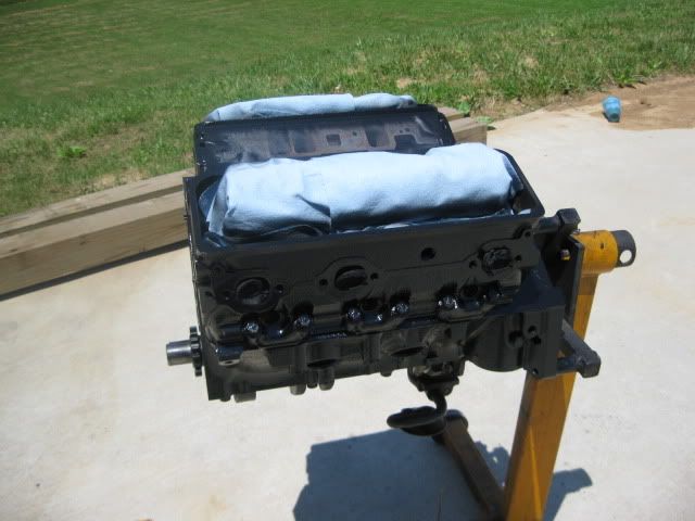
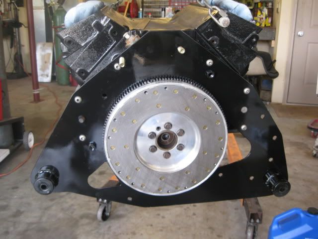
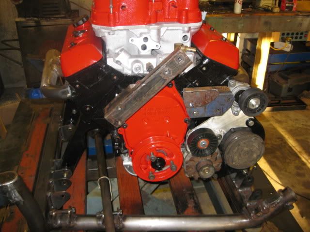
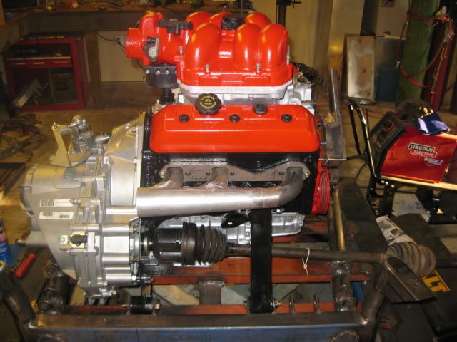
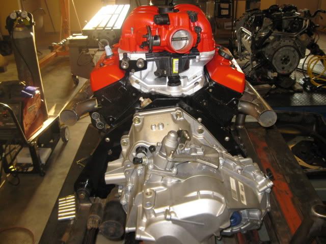
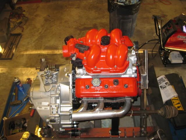
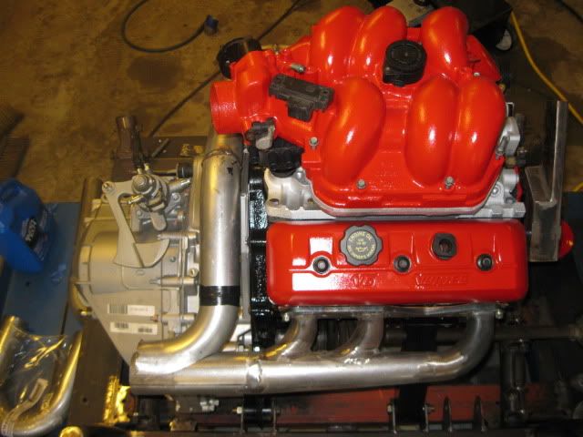
All the engine work is complete and the engine is painted:
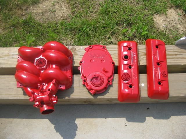
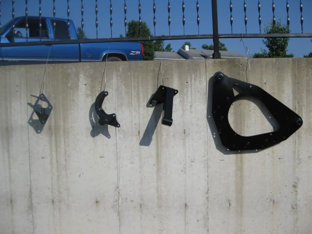
Lot of other odds and ends are finished and painted:
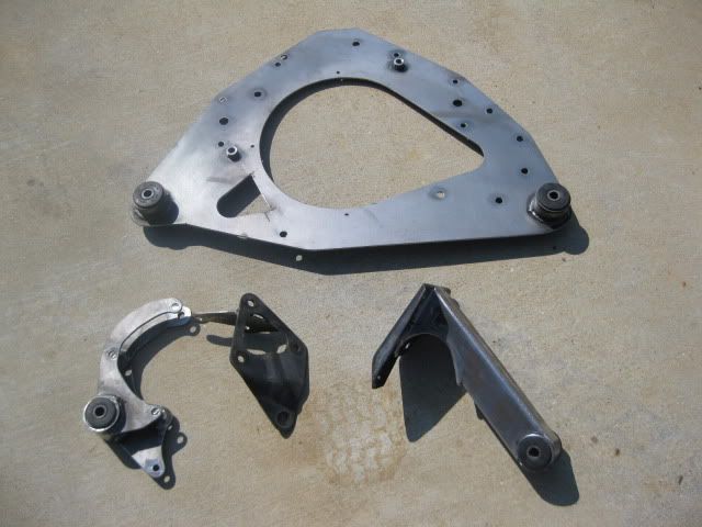
Adapter plate and engine mounts with rubber bushings:
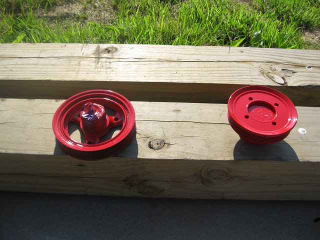
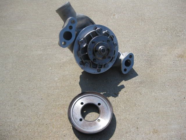
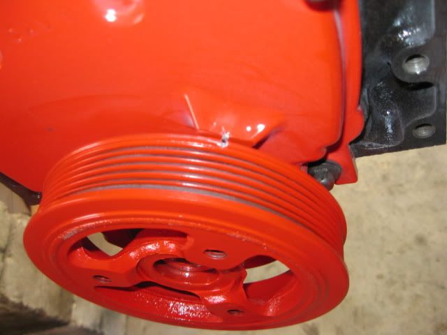
Balancer, water pump and pulley:
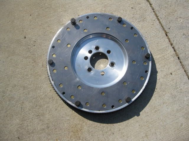
Fywheel is also complete and ready for installation:
I am hoping on Sunday I get the last of the engine mount brackets welded to the tubular cradle and engine/tranny/accessoried/intake/exhaust assembled together for a test fit/inspirational photo op... Then the cradle will be painted and I will finish up the welding on the offset housing and move on to the thermostat housing/coolant lines.
IP: Logged
06:31 PM
May 31st, 2010
fieroguru Member
Posts: 12128 From: Champaign, IL Registered: Aug 2003
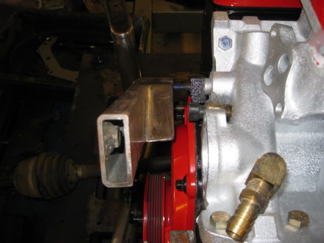
Pretty much the theme of the weekend was 2 steps forward and 1 step back... I mocked up most of the parts for this swap with a SBC and that caused some issues when I tried to install them on the 4.3...
As the engine was being put together for the last time, the aluminum oil pan was slightly wider than the steel one on the mock up engine and would not let the alternator bolt up - some work with a grinder on a couple of the reiniforcing ribs on the oil pan and counter sinking one bolt on the flange and the alternator and AC compressors went on w/o any further issues. The oil pan also needed modified to clear the welded on dowel pin on the back side of the adapter plate... hole saw give it the needed clearance. It also needed notched to clear the locations where the starter protrudes through the adapter plate.
The flywheel went on w/o issue:
The depth of the 3.1 balancer hub ended up being within .015" of being perfect, so it I didn't modify it any further. Now the timing cover was another story. On the SBC the timing tab was about 1" above the balancer, not so on the 4.3... it ran right into the balancer. Used the grinder to get the needed clearance. Also took this time to mark, notch and paint the TDC location on the balancer.
With the AC/Alt/Mount bracket on the engine, the rear engine mount went on w/o issue and the engine was mounted to the cradle so the locations of the front engine mount tabs could be determined and tack welded into place. While doing this I noticed the aluminum oil pan sticks below the bottom of the cradle by about 1/16"... more annoying than anything else (the SBC one was 1/4" above), so I used larger washers to shim the 4 corners of the cradle.
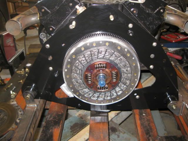
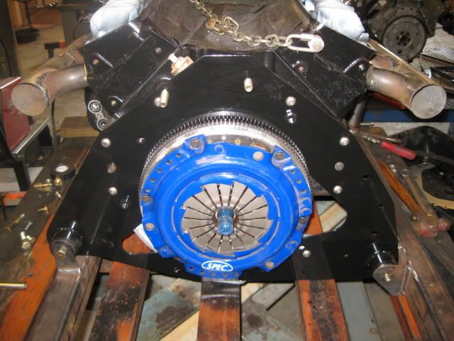
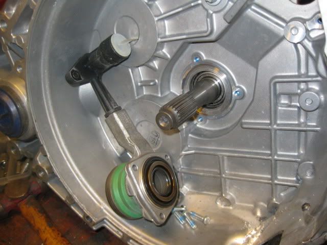
Installed the clutch... ($25 Exedy clutch for an import and a fiero Spec Stage 2+ pressure plate)...I didn't have an alignment dowel for the clutch, but one from the collection worked just fine.
While at this stage, I took the opportunity to verify the depth of the pressure plate fingers vs. the available range of motion of the HTOB. There is about .54" of available motion within the HTOB and the position of the pressure plate fingers left only about .165" to disengage the clutch before maxing out the range of motion... this might work just fine, but I wanted it to be more centered or biased to the wear side. On my 92-94 HTOB getrag, I made a spacer to shim the HTOB into the proper range of motion, but the F40 is slightly more difficult. The back side of the HTOB contains the seal for the input shaft... but a spacer is still doable. The aluminum spacer was machined to fit the round recess in the case and on the HTOB housing and spaced the HTOB from the case by .175... so now there would be .34" on the release side and .20" on the wear side.
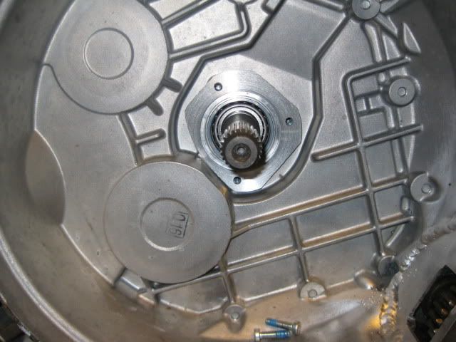
Installing the transmission turned out to be a bear.... The fine splines on the input shaft and the clutch disk had to be perfectly aligned... faught it for about 2 hrs and had it off and on about 8 times before it finally lined up... Then installed the starter w/o issue since the oil pan has already been clearanced... pleased to see that I still had plenty of clearnace between the crossmember and solenoid...
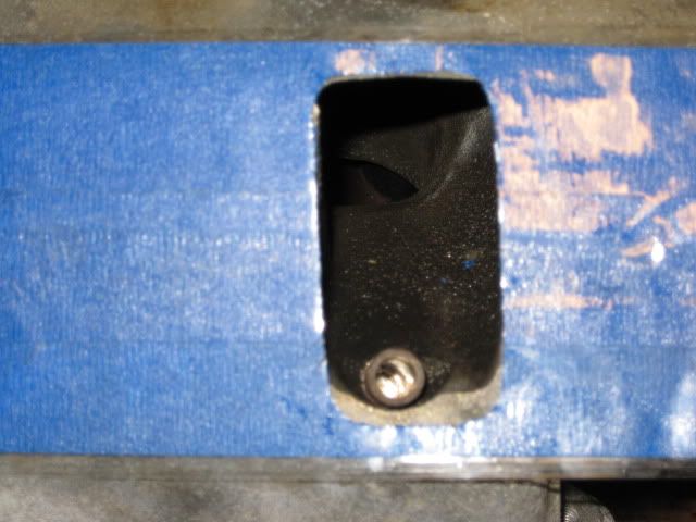
On the SBC, the inboard passenger tripod would hit the original starter pad by about 1/16", so I had clearanced the starter pad on the 4.3 and the passenger tripod now clears w/o issue.
The offset housings for the water pump are also going to be an issue. The rear one a quick hit with he grinder allowed it to clear the timing cover, but the front one needs a major rework... balance shaft cover has a different shape and is much taller than a typical SBC cover... oh well..
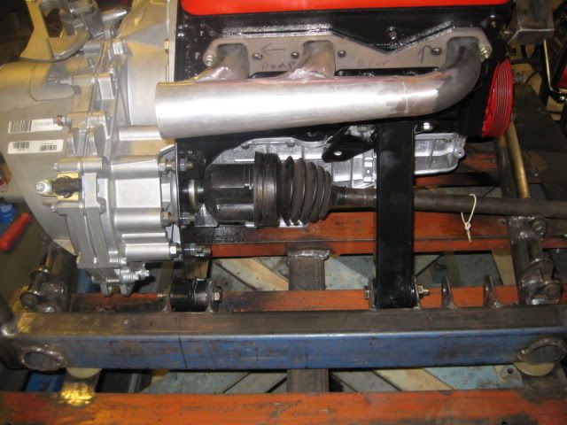
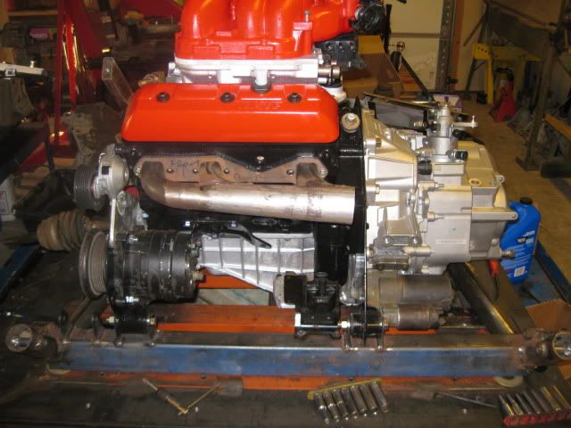
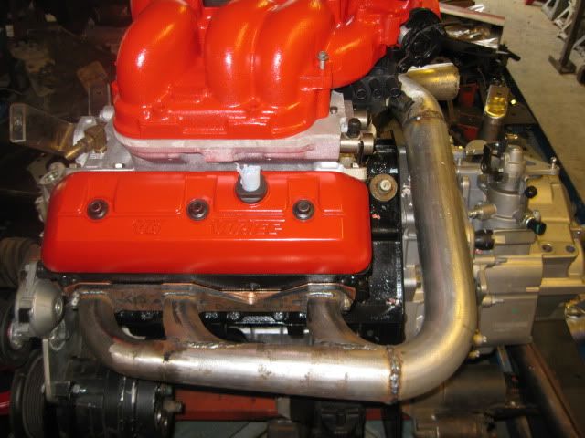
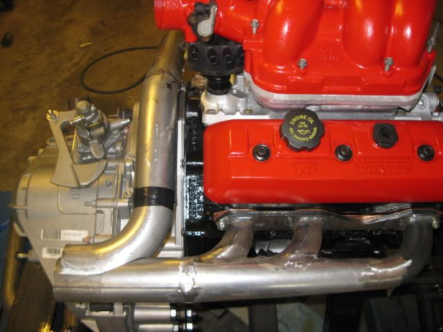
So after the offset housing issue, I decided to start putting the upper intake back together (torn down for machining/painting) and find a location for the ignition coil. Also put the exhaust manifolds on for good measure....
Probably will not get back at this till next weekend...
IP: Logged
09:20 PM
Jun 6th, 2010
fieroguru Member
Posts: 12128 From: Champaign, IL Registered: Aug 2003
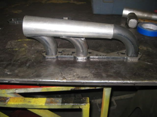
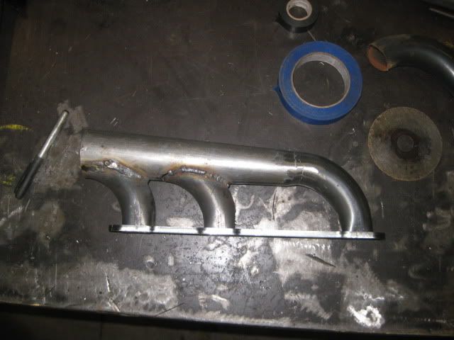
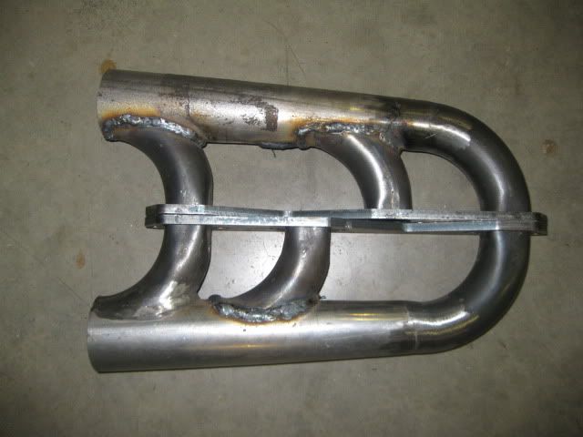
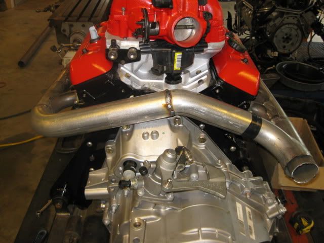
Finished welding all the tubes and flanges on the manifolds, then moved on the fabbing up the crossover pipe to the rear. The manifold taper stops at 2 1/2 and the tubes remain 2 1/2 until both sides merge together where the outlet will be 3".
As you can see I am still working on the Y portion and forming the 2 1/2" tubes to end with a 3" OD at the outlet. From there the 3" exaust will turn 180, go across the engine bay under the truck and then 180 again into a flowtech afterbuner 3" in dual 2 1/2" out crossflow muffler. I am routing the exhaust this way to have room for a cat/converter if I ever end up needing it. Till then, there will be a spiral muffler insert in the length of 3" tube... the flowtech afterburner is a realatively loud muffler and this should help take the edge off.
I still need to purchase the muffler, so it will be a little while before I can finish the exhaust.
[This message has been edited by fieroguru (edited 06-06-2010).]