I do not consider my fabrication speed all that great. It could be much, much faster if I had better tools (and the room for them). Pretty much all the frabrication (except the flexplate) has been done with a sawsall, grider and a 220V lincoln mig welder - with flux core wire.
Patience, attention to detail, and willingness to redo it if you are not happy are key.
IP: Logged
07:38 AM
blackrams Member
Posts: 31841 From: Hattiesburg, MS, USA Registered: Feb 2003
Patience, attention to detail, and willingness to redo it if you are not happy are key.
Aw yes, all those little things I seem to lack, not to mention the sawsall, grider and a 220V lincoln mig welder - with flux core wire, and yes, mechanical knowledge. But, I can and do appreciate good work and I have witnessed that. Play On!!!!
------------------ Ron
It's the Soldier, not the reporter Who has given us the freedom of the press. It's the Soldier, not the poet, Who has given us the freedom of speech. It's the Soldier, not the politicians That ensures our right to Life, Liberty and the Pursuit of Happiness. It's the Soldier who salutes the flag, Who serves beneath the flag, And whose coffin is draped by the flag.
IP: Logged
08:45 AM
Dec 4th, 2007
fieroguru Member
Posts: 12128 From: Champaign, IL Registered: Aug 2003
Not much going on, but I tracked down the part #'s for the 440T4/4T60axles.
Source: 89 Pontiac 6000 with 4speed auto, light duty brakes, 30MM nut and 31 spline.
LEFT side drive axle 8471, A1 CARDONE PN 601078, ADVANCE AUTO PARTS CV 10029 RIGHT side drive axle 8430, A1 CARDONE PN 601115, ADVANCE AUTO PARTS CV 10076
From Napa: p/n 95-9178 and 95-9208
I purchased mine from: A-1 Drive Shaft (800-228-0356) 47-557 ($49) and 47-558 ($49) Total with shipping = $118.00 (and no core charge). Should be here in a few days.
[This message has been edited by fieroguru (edited 06-25-2008).]
IP: Logged
01:17 PM
Dec 8th, 2007
fieroguru Member
Posts: 12128 From: Champaign, IL Registered: Aug 2003
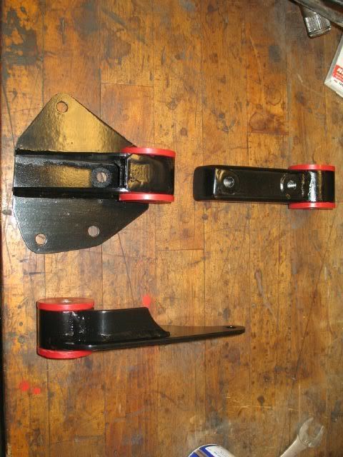
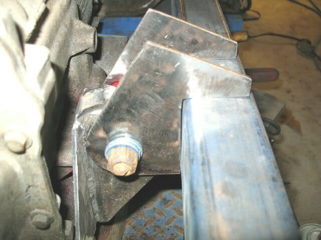
Spent the day working on the mounts some more. First thing I did was redo the rear tabs for the crossmember to add a portion to the bottom and make them a "C" that fits around the 2x3 crossmember. I decided to make all 4 rear tabs the same that will mount to the cradle.
Here they are being cut/smoothed/drilled with all 4 stacked:
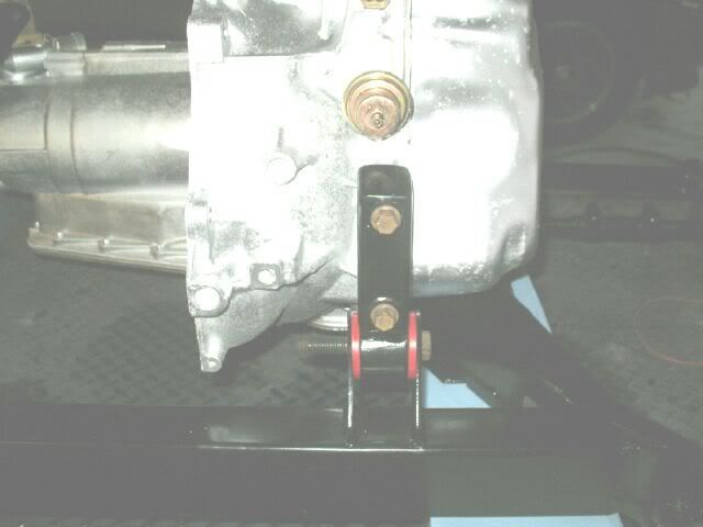
Then is was time to make the rear engine mount. It was made from 3" x 3/16" steel bar, and another small piece of 3x16" steel.
Here are the rear tranny and engine mounts on the 2x3 crossmember:
The front engine mount was made from 2"x3/8" steel bar. It takes the place of the AC to engine mount shown earlier in this thread. Remember those crossmember tabs I just reworked, well I cut them to eliminate the short leg (rested on top of crossmember) and used them for the front engine mount.
The axles came in on Thursday, so the engine location will be finalized on Sunday and the mounts welded in place.
[This message has been edited by fieroguru (edited 12-08-2007).]
IP: Logged
05:09 PM
Dec 9th, 2007
vortecfiero Member
Posts: 996 From: Toronto Area, Canada Registered: Feb 2002
Not a lot of pics for today, but the mounts are finally done.
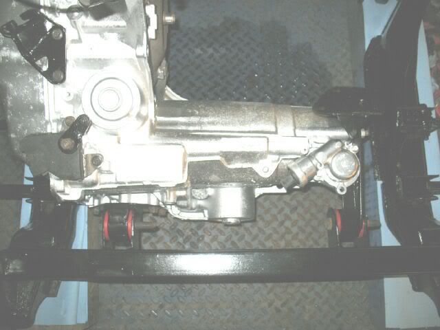
I took the new axles, compressed them fully, and wired them in the compressed location. Then installed them in the tranny and measured the ends of the axles to the bolt in the lateral links. Adjusted the tranny to get the axle ends at the same location on each side. I could not get it perfect. To be perfect, the tranny needed to go to the driver side another 1/8", but the side of the cradle was getting in the way, so I left it 1/8" off center.
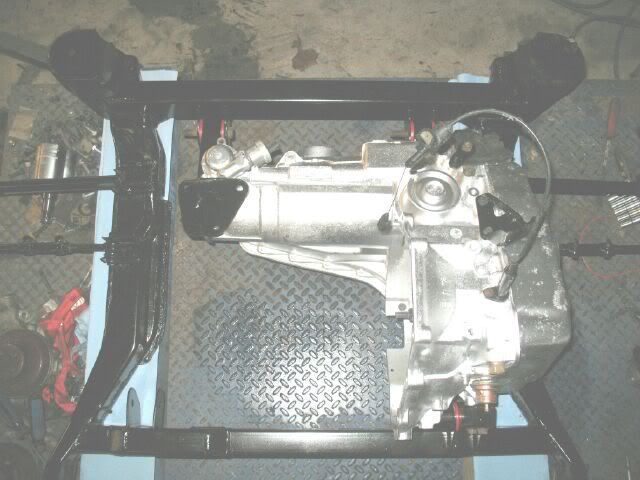
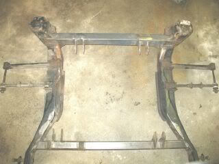
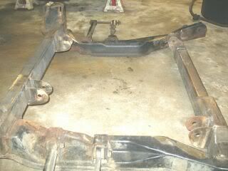
The rear mounts were tack welded in place and then the engine/tranny/cradle was test fitted again. With everything in the proper location, the front mounts were tack welded. Then everything was removed from the car again, dismantled and the brackets on the cradle welded solid. Once they cooled off, the rear brackets were cut to allow the sway bar to clear them. Now the cradle looks like this!
Ron (Blackrams) came over and helped with the engine/tranny dissassembly (did most of it while I was welding) and removing all the stuff from the engine bay. Getting very close to a cleaning/painting party
I am glad the mounts are finally done!
IP: Logged
04:34 PM
blackrams Member
Posts: 31841 From: Hattiesburg, MS, USA Registered: Feb 2003
First, let me say, this is one slick project and Paul really has his stuff together when it comes to building a ride.
Secondly, I really came to Paul's to learn from him. Yes, I did do a little dismanteling while there, taking stuff apart is easy, it's putting them back together correctly that gets interesting.
------------------ Ron
It's the Soldier, not the reporter Who has given us the freedom of the press. It's the Soldier, not the poet, Who has given us the freedom of speech. It's the Soldier, not the politicians That ensures our right to Life, Liberty and the Pursuit of Happiness. It's the Soldier who salutes the flag, Who serves beneath the flag, And whose coffin is draped by the flag.
IP: Logged
05:52 PM
Dec 10th, 2007
vortecfiero Member
Posts: 996 From: Toronto Area, Canada Registered: Feb 2002
vortecfiero, have you ever looking into running an 96+ dist (crab style) with the 91-95 ecm? That dist might be low enough to allow the upper portion of the intake to be rotated. It would require a spacer since the upper intake is not symetical and this would make the EGR inoperable, but the throttle body would be in the center and keep from trimming the decklid hinge.
I had never though about Plexiglass, that would work real well too! You will have to give me some to try next time, or I will be forced to continue with the cardboard!
I took a vacation day on Tuesday so I will be back at it mid week for once.
[This message has been edited by fieroguru (edited 12-10-2007).]
IP: Logged
07:34 PM
PFF
System Bot
DIY_Stu Member
Posts: 2337 From: Republic of TX Registered: Jun 2007
I'm building my own 4.3. Just because I've had a 4.3 since I've been driving. 4.3 Suzuki Samuri. Wow that thing rocked. 4.3 C1500 Ran it up to 300K and abused daily. Sat with a 1/4 tank for a year and fired right up as well as passed emissions! So Why not keep on with the 4.3
I've got a 95 Blazer 4.3 Newer 2002 intake I have to get a new dizzy prefer the Crab style. Build custom intake etc etc etc Bare block fresh from the machinist
So now all I have to do is finish the engine then put it in.
I don't see why the crab style dizzy wouldn't work. Love your mounts and Vortecs March Overdrive kit both of you have given me many ideas.
IP: Logged
10:14 PM
Dec 11th, 2007
fieroguru Member
Posts: 12128 From: Champaign, IL Registered: Aug 2003
Vacation Day! Every day should be a vacation day and every day in Dec should be 73 degrees!
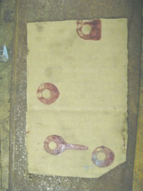
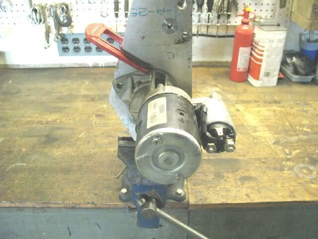
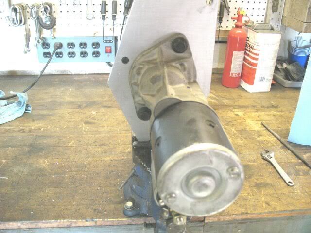
A few loose ends were tied up this morning. The original starter location (rotation) would not clear the manifold (solinoid stuck out too far), so it was rotated down. While it was clamped in place during mockup, I scribed the sides of the starter so new holes could be drilled and tapped. Old Position: New Position:
Then I welded caps on the top of the front tranny mount and the top of the accessory bracket.
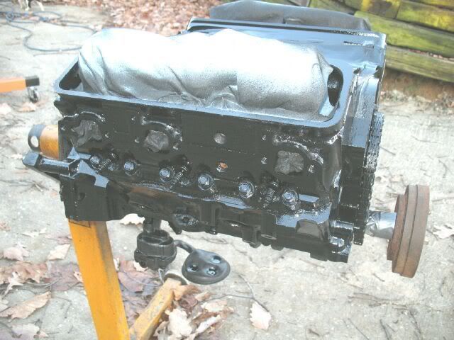
The rest of the day was dedicated to cleaning and painting.
The engine is now gloss black. I will get a gasket set to seal the engine back up, and maybe some bearings and a timing chain just for good measure. Aside from that, I am not planning on pulling the heads/cam or anything else.
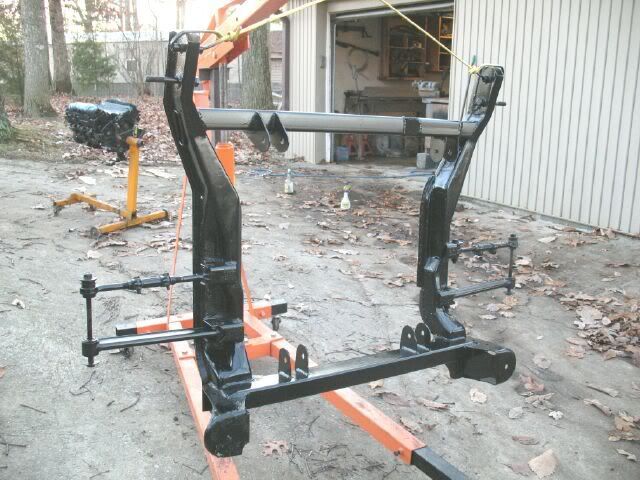
The cradle is now semi-gloss black:
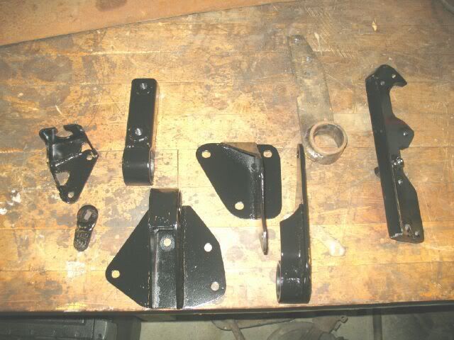
The mounts/brackets are semi-gloss as well, except the front engine mount (it still needs the lower AC/Alternator tab welded to it, and I have not made the tab yet).
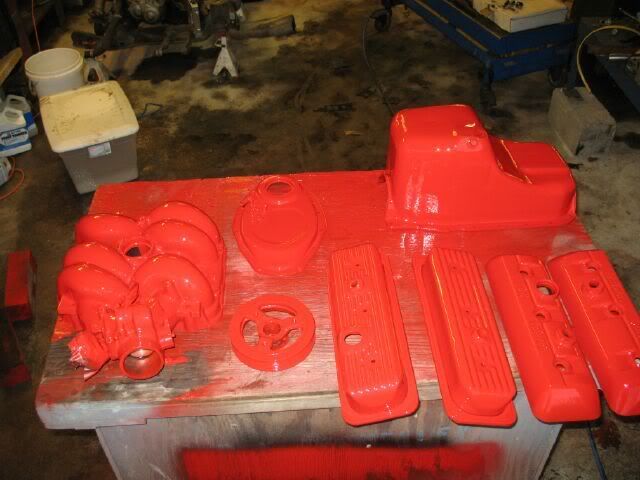
This engine is going in a red 88, so I decided to stick with the fiero V6 color seqence for the most part. The upper intake and valve covers will be red as well as the timing cover, balancer, and oil pan. There are two sets of valve covers, one is the stamp steel that came on the 92-95 CPI engine and the others are plastic from the 96+ engines. I have not decided which ones will be used, so they both were painted. The steel ones have an ugly oil fill (stick up above the valve cover several inches) and the plastic ones have a prettier oil fill.
I am looking for this measurement from a 96+ 4.3 with the crab style dist, so anyone have one to measure?
IP: Logged
06:39 PM
fieroguru Member
Posts: 12128 From: Champaign, IL Registered: Aug 2003
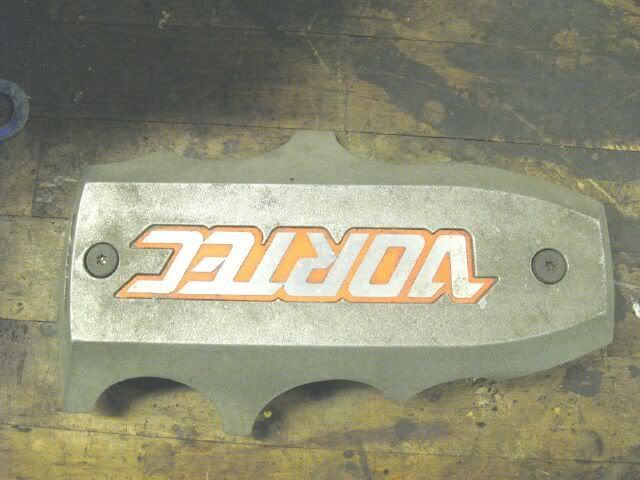
Something else to think about is what am I going to do with this?
This is the orientation that it would normally be as viewed from the rear of the fiero. If I am successful at rotating the upper intake, then it would be right side up. It is not symetric, so the only way to flip it around (without flipping intake) is to cut the little legs off, biut then it would not fit as well to the runner contours. If I use the plastic valve covers, they already say VORTEC on them, so this saying VORTEC could be redundant.
So should I just fill the thing in and get a FIERO logo for it?
IP: Logged
07:01 PM
Russ544 Member
Posts: 2136 From: S.W. Oregon Registered: Jun 2003
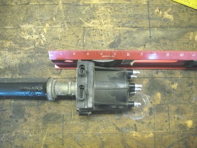
It's VERY challenging trying to get a measurment from my 00 Blazer (damn modern vehicles), but +/- 1/8" I'm calling it 4.5" from the manifold flat, where the hold down clamp is (should be same as bottom of dist hold down collar), to the top of the cap.
hope that works for you, Russ544
------------------ It's just like building a canoe out of a log. first you cut down a tree........ then you cut off everything that doesn't look like a canoe.
[This message has been edited by Russ544 (edited 12-11-2007).]
IP: Logged
07:04 PM
fieroguru Member
Posts: 12128 From: Champaign, IL Registered: Aug 2003
Thanks Russ544! That is promising. Here is one of my spare intakes to show the flipped configuration and the clearance:
Without the needed spacer to properly seal the intake (not symetric) the clearance is 3 7/8". So a 3/4" spacer should provide the needed clearance. I might just have to pick up one of the 96+ dist and do some experimenting. The flipped orientation would simplify the cold air system and save the decklid hinge/decklid from being notched to clear the throttle body. Since the egr would have to be removed, then it would not be sticking out the right side of the intake anymore. This is definately worth exploring some more.
IP: Logged
07:49 PM
DIY_Stu Member
Posts: 2337 From: Republic of TX Registered: Jun 2007
If you get the dizzy and end up not using it but it will fit then I'll gladly buy it from you. Thanks Russ544 for the measurement, I've needed it for quite a while just haven't asked yet. I see you used the SD plate too, I have an arch copy but I'm thinking I like the SD plate better since it doesn't require a mini starter and brackets. Your flexplate scares the living crap out of me though. Did you know there is a candidate for a BOLT in Flexplate?
Thanks to Sinister Performance's great documentation and pictures """The flexplate and crank mounting for the flexplate is most interesting. It looks like the standard late SBC mounting bolt pattern and hub size. There is a steel bushing pressed into the crank so it will work with the smaller, FWD torque converter. GM p/n for the flexplate is 12568922. """
This flexplate is the same diameter as the 60�V6 But has the SBC bolt pattern.
gmpartsdirect.com lists this part at GM PART # 12568922 CATEGORY: Engine Flywheel PACK QTY: 1 CORE CHARGE: $0.00 GM LIST: $98.06 OUR PRICE: $58.14
Not bad if it fits. I'll be picking one up.
You not alone in your swap but you're leading the pack.
IP: Logged
09:56 PM
Dec 12th, 2007
fieroguru Member
Posts: 12128 From: Champaign, IL Registered: Aug 2003
I see you used the SD plate too, I have an arch copy but I'm thinking I like the SD plate better since it doesn't require a mini starter and brackets. Your flexplate scares the living crap out of me though. Did you know there is a candidate for a BOLT in Flexplate?
Thanks to Sinister Performance's great documentation and pictures """The flexplate and crank mounting for the flexplate is most interesting. It looks like the standard late SBC mounting bolt pattern and hub size.
This flexplate is the same diameter as the 60�V6 But has the SBC bolt pattern.
Yes, my adapter plate was based on the Z-style and SD sells a plate with the engine tranny rotated relative to each other (like the one I am using), but I do not know for sure that is what it is. I am also adding spacers to get 11/16" adapter plate thickness. My SBC car runs an archie kit.
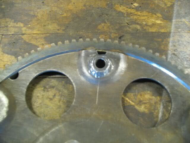
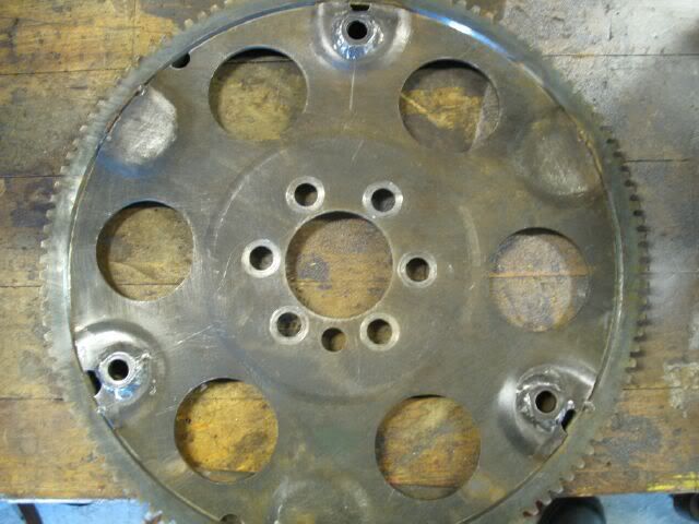
I am curious why my flex plate scares you... It is a normal 4.3 flex plate turned down to accept the nissan ring gear and then the ring gear is welded on in 6 locations to the flex plate.
About the bolt in flex plate solution, SD sells one. The one off the 5.3 LS4 will not work. The SD plate/starter combo was designed around the nissan ring gear/nissan starter with a slightly different diameter and larger teeth, so unless you swap ring gears or find another starter it will not just be a bolt in solution.
[This message has been edited by fieroguru (edited 12-12-2007).]
IP: Logged
07:21 AM
DIY_Stu Member
Posts: 2337 From: Republic of TX Registered: Jun 2007
Well I either looked at it wrong or something. I think I merged two flexplate modification pictures in my head. Because I looked again and it's different than I remembered. My memory was telling me that you cut the CENTER CENTER section out just past the crank bolt holes then cut a matching piece out of another flexplate and welded them of there. Just having looked again I see that all you did was shave down the original and weld on the new ring gear just like the manufacturer does. So never mind that statement. I'm still going to get the new flexplate just to see what I can come up with for a starter. Who knows they may mesh up somehow.
Stu
IP: Logged
06:12 PM
Russ544 Member
Posts: 2136 From: S.W. Oregon Registered: Jun 2003
Well I either looked at it wrong or something. I think I merged two flexplate modification pictures in my head. Because I looked again and it's different than I remembered. My memory was telling me that you cut the CENTER CENTER section out just past the crank bolt holes then cut a matching piece out of another flexplate and welded them of there. Just having looked again I see that all you did was shave down the original and weld on the new ring gear just like the manufacturer does. So never mind that statement. I'm still going to get the new flexplate just to see what I can come up with for a starter. Who knows they may mesh up somehow.
Stu
you haven't gone compleatly crazy stu . there was a build thread on the forum a wile back with a pieced together flywheel like you discribe. and I agree with you that THAT thing was scary. certainly nothing that Guru would even concider doing however.
[This message has been edited by Russ544 (edited 12-12-2007).]
IP: Logged
06:23 PM
fieroguru Member
Posts: 12128 From: Champaign, IL Registered: Aug 2003
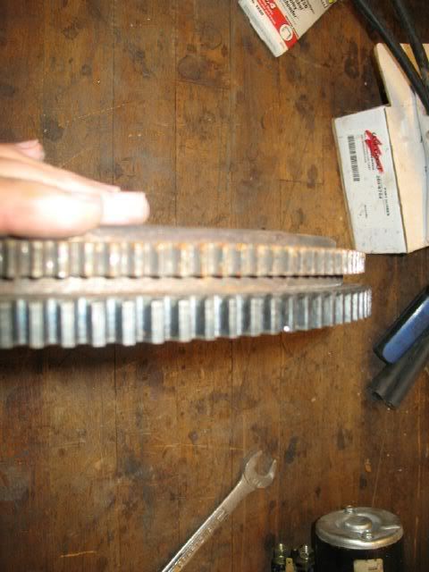
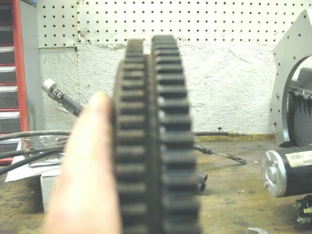
Just for research info, here is a stock fiero ring gear next to the nissan ring gear. The Nissan one has 120 teeth, but I have never counted the fiero one. The teeth on the nissan one are thicker and the outside diameter of the nissan is about 1/8" larger.
Does the LS4 have the same external balance as the 86+ SBC? If it did, then it would be cool to find a combination of stock parts that could use this flex plate. The original Z-kit with the nissan starter/flexplate was designed 20-some years ago, so there may be more face mount starter options to pick from now.
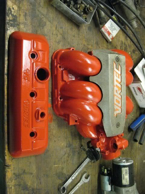
Here is a better pick of the intake with the dirty center piece as well as one of the valve covers. I am about 80% sold on the plastic covers with a FIERO logo on the center piece.
IP: Logged
07:08 PM
PFF
System Bot
DIY_Stu Member
Posts: 2337 From: Republic of TX Registered: Jun 2007
I have be told by the spousal unit that I can not spend any $$$ on the 4.3 swap till after Christmas, so my gasket kit will have to wait.
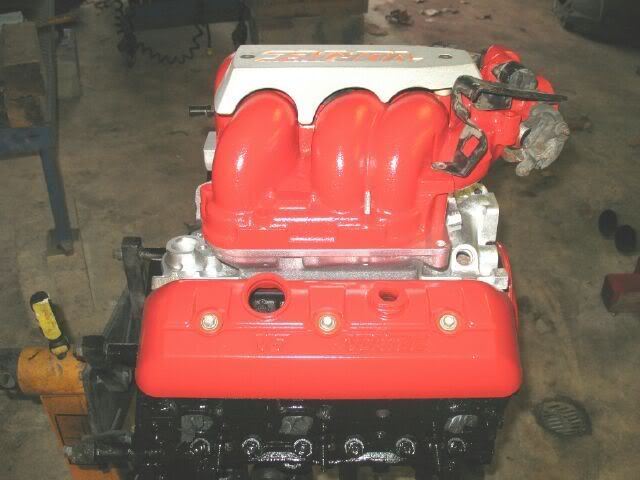
I did get the lower intake and the tranny cleaned up and painted aluminum. Here is a mock up of the engine with the intake and valve covers on:
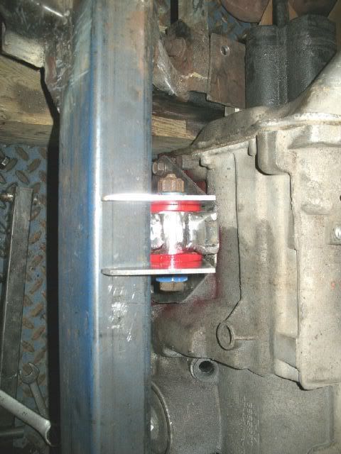
The 3 tranny mounts had the bushings reassembled.
Call me anal, but every bolt that attaches the mounts to the tranny are now 15mm and nearly all of them are the same length (took the time to sort them out and cut them to length). Here is the tranny assembled on the cradle again:
IP: Logged
06:01 PM
Dec 25th, 2007
vortecfiero Member
Posts: 996 From: Toronto Area, Canada Registered: Feb 2002
vortecfiero, have you ever looking into running an 96+ dist (crab style) with the 91-95 ecm? That dist might be low enough to allow the upper portion of the intake to be rotated. It would require a spacer since the upper intake is not symetical and this would make the EGR inoperable, but the throttle body would be in the center and keep from trimming the decklid hinge.
I had never though about Plexiglass, that would work real well too! You will have to give me some to try next time, or I will be forced to continue with the cardboard!
I took a vacation day on Tuesday so I will be back at it mid week for once.
lol omg i just found this ! I see you are as frugel as me (cheap) lol I found my plexy in a garbage at a display company... they throw out lots of good materials from steel to plastic
Yes the crab style dist is on my list of things to try... keep in mind im using syclone intakes now. Its a 2 part system and im even considering making a new upper plennum or modding a TPI v8 upper..
as you can see its tight.. but that never stopped me before !
IP: Logged
11:25 AM
fieroguru Member
Posts: 12128 From: Champaign, IL Registered: Aug 2003
Not much else going on with this project this week. I did do some looking for various length TV cables for the trans. I need to put the engine back with the tranny and measure the needed cable and get it ordered. Plus the gasket kit and bearings... Hope to spend some $$$ right after the first of the year.
IP: Logged
06:19 PM
Dec 26th, 2007
vortecfiero Member
Posts: 996 From: Toronto Area, Canada Registered: Feb 2002
Something else to think about is what am I going to do with this?
This is the orientation that it would normally be as viewed from the rear of the fiero. If I am successful at rotating the upper intake, then it would be right side up. It is not symetric, so the only way to flip it around (without flipping intake) is to cut the little legs off, biut then it would not fit as well to the runner contours. If I use the plastic valve covers, they already say VORTEC on them, so this saying VORTEC could be redundant. So should I just fill the thing in and get a FIERO logo for it?
I considered making a new one out of billet aluminum... and also considered cutting the logo out in a rectangle, getting another cover and cutting the rectange out of it for a tight fit from the first one, eliminating the saw/dremmel etc thickness in the cut my welderguy said he could copy it in sheet alum... but wanted about $200.
[This message has been edited by vortecfiero (edited 12-26-2007).]
IP: Logged
12:06 PM
Raydar Member
Posts: 40728 From: Carrollton GA. Out in the... country. Registered: Oct 1999
Originally posted by vortecfiero: ...im even considering making a new upper plennum or modding a TPI v8 upper..
What about the entire TPI setup (lower, runners, and plenum) or even the equivalent LT1 pieces, with the appropriate ports "sectioned" out of the middle. It would require some careful cutting and welding, but ought to look amazing.
IP: Logged
12:23 PM
fieroguru Member
Posts: 12128 From: Champaign, IL Registered: Aug 2003
Originally posted by Raydar: What about the entire TPI setup (lower, runners, and plenum) or even the equivalent LT1 pieces, with the appropriate ports "sectioned" out of the middle. It would require some careful cutting and welding, but ought to look amazing.
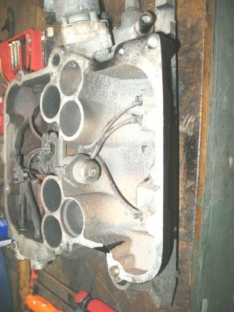
I can get some pics this evening, but the outer shell of the lower CPI intake manifold can be cut/removed and it will leave you with the lower half of a tunnel ram. It would need to be converted to conventional injectors, the weep hole in port #3 welded up, and an upper intake plenum made, but it could easily look like a smaller version of the Holley Stealthram.
Keep these types of discussions up and I may never get this thing finished!
IP: Logged
01:40 PM
fieroguru Member
Posts: 12128 From: Champaign, IL Registered: Aug 2003
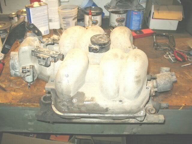
Here is the inside of the CPI intake (one of my spares). The runners are 1.75" in diameter compared to 1.470" for the stock TPI. Notice the runners travel up and into the center, then they come back over the top. By removing the portions of the intake painted black, you will be left with an intake with a tunnel ram shape (you could even retain the egr!).
I also put the engine back on the cradle with the tranny and measured the TV cable. 29" of outer housing length (tranny case to (throttle body bracket) would work just fine. The ones I found on ebay over the holiday were 26" (probably 25" based on my measuring location vs. theirs) and 39". If I can not find the exact cable I need, I will probably get a long one and cut it down to fit.
[This message has been edited by fieroguru (edited 12-26-2007).]
IP: Logged
06:07 PM
Dec 27th, 2007
vortecfiero Member
Posts: 996 From: Toronto Area, Canada Registered: Feb 2002
What about the entire TPI setup (lower, runners, and plenum) or even the equivalent LT1 pieces, with the appropriate ports "sectioned" out of the middle. It would require some careful cutting and welding, but ought to look amazing.
I considered it... but probably too much work for no real benefit other than aesthetics. It would look cool though
IP: Logged
12:57 AM
Dec 28th, 2007
fieroguru Member
Posts: 12128 From: Champaign, IL Registered: Aug 2003
Decided to burn my last vacation day for 2007 today and get a jump start for the holiday weekend to tie up some loose ends.
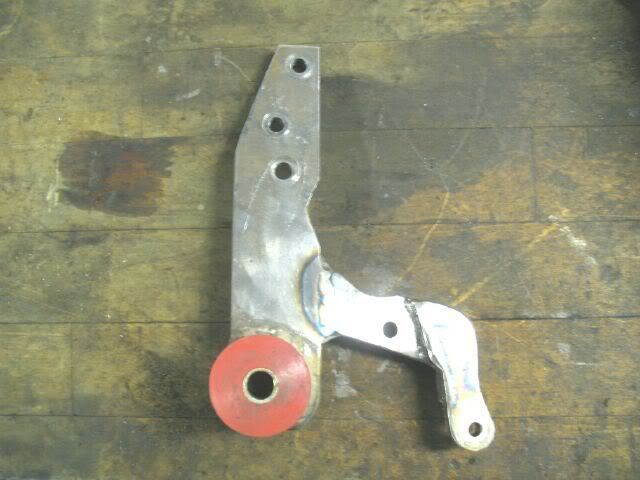
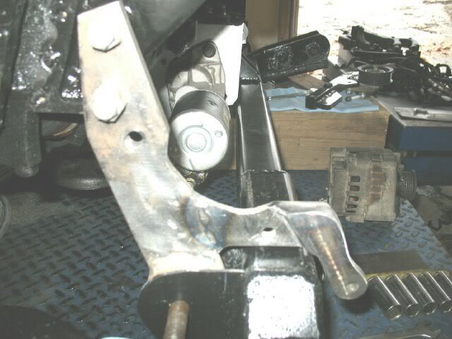
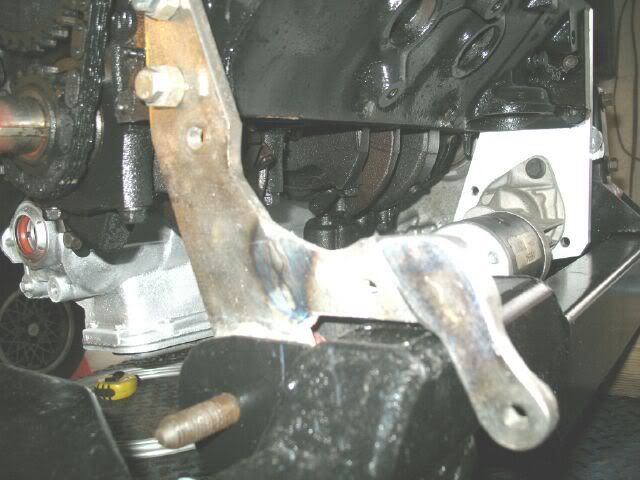
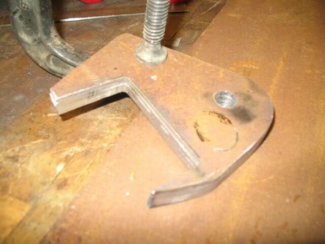
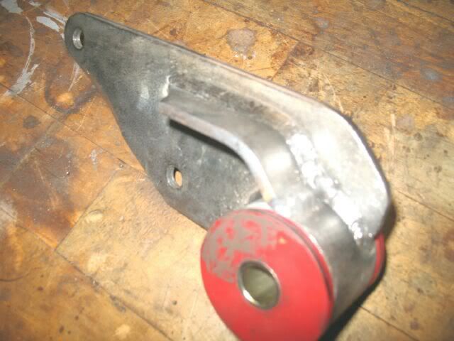
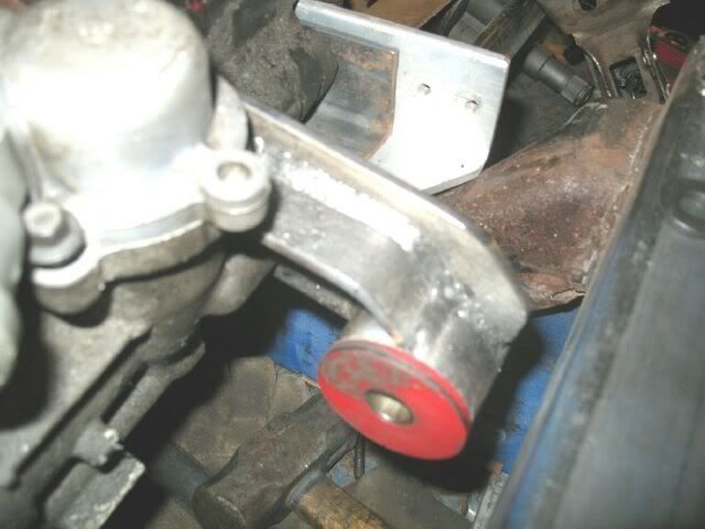
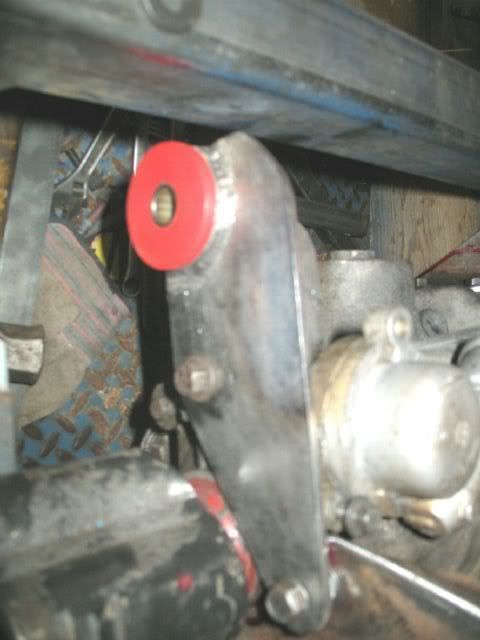
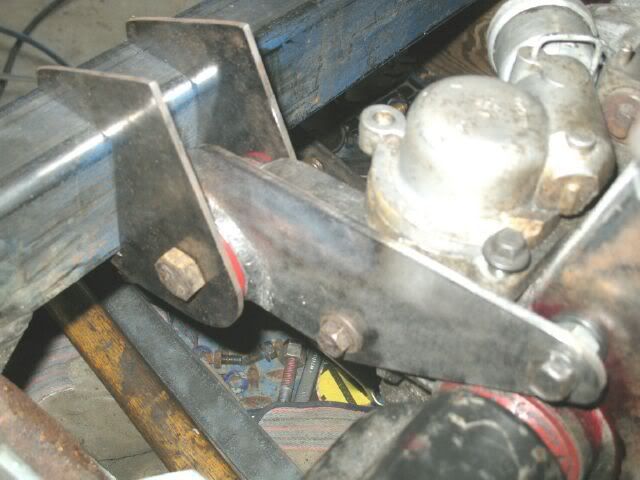
The only engine/tranny mount not complete was the front engine mount. It needed a couple of pieces added to it to tie into a second AC compressor hole and to the lower alternator bolt hole. The bracket is made of 3/8" steel and clears the front crossmember by about 1/4".
I added a 1" x 1/4" strap to the back side of the upper alternator bolt to help stiffen things up a bit.
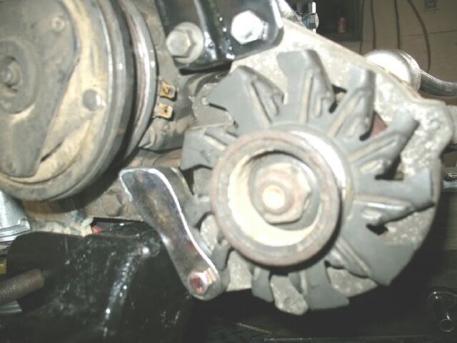
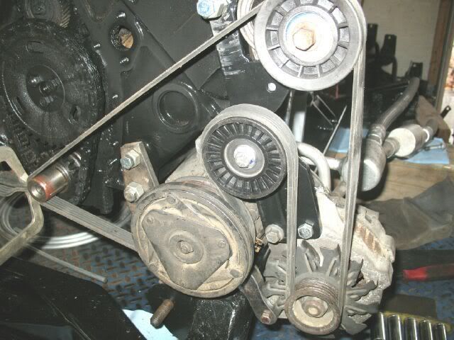
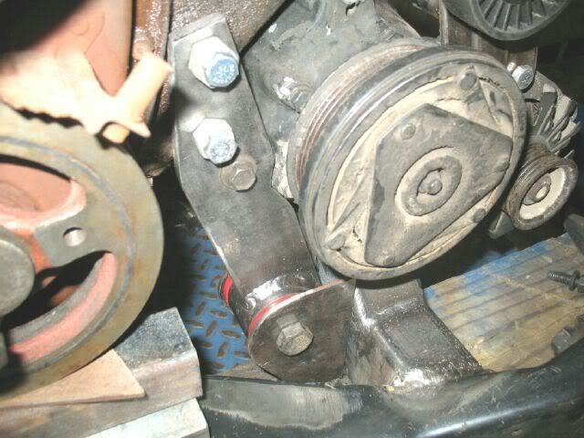
Here is the accessory drive again (minue balancer) with all the brackets installed:
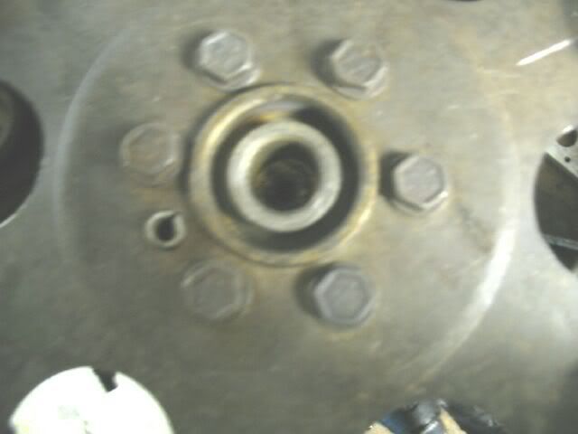
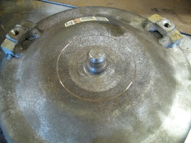
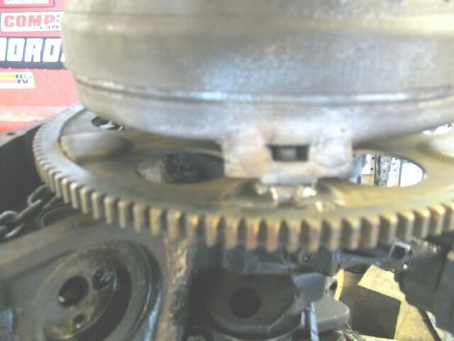
Next the torque converter/flex plate was revisited. Here is the crankshaft bushing to support the torque converter:
With the torque converter just sitting on the flex plate, there is a 0.13" gap between the flex plate and the mounting tabs on the torque converter. This space is due to interferance between the crankshaft bolts and the center contour of the torque converter.
I spun the torque converter around while sitting on the crankshaft and here you can see the scratch mark from the crankshaft bolts:
One way to eliminate the interferance and resulting gap is to round off the outer edges of the crankshaft bolts. Another way is to just use a 0.13" spacer to close the gap without needing to modifiy the crankshaft bolts.
I will be using the spacer method, but understand that the reason this is possible is due to the adapter plate thickness I am using.
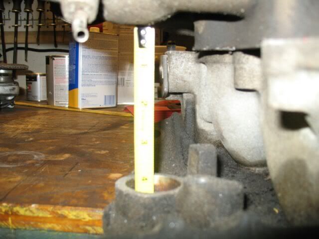
With the torque converter fully seated in the tranny and using a ruler accross the bellhousing face... 0.57" is the distance from the face of the transmission bellhousing to the face of the torque converter mounting tabs. If the torque converter tabs are further than this from the adapter plate - bad things will happen.
With the torque converter resting on the crankshaft bolts... 1.16" is the distance between the SBC bellhousing face and the torque converter mounting tabs. 0.70" is the thickness of the adapter plate So 0.46" is the distance from the adapter plate to the face of the torque converter mounting tabs. There is 0.11" of clearance for this swap with using the 0.13" spacers and no need to round off the edges of the crankshaft bolts.
CAUTION - the reason this works for me is the 0.70" adapter plate thickness. The adapter is actually 0.58" thick, but I used spacers to make it 0.70" thick. This gave me an extra 0.12" of room which provided the space needed to use the 0.13" spacer. If I had just used the 0.58" adapter, the adapter plate to torque converter mounting tabs would be 0.58" which is further than the 0.57" of room within the tranny, causing a bind and eventually leading to bad things.
Next step is to make the needed spacer. That will be a project for Saturday!
[This message has been edited by fieroguru (edited 12-29-2007).]
IP: Logged
03:43 PM
PFF
System Bot
Dec 29th, 2007
fieroguru Member
Posts: 12128 From: Champaign, IL Registered: Aug 2003
I used 2 washers to make spacers the needed thickness - use a caliper to measure each washer and them pick and choose them to get the needed thickness. Then the washers were welded to the flexplate.
No more gap and now the flexplate work is complete!
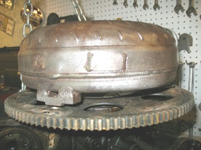
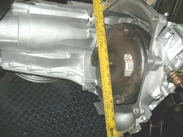
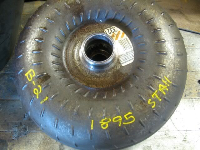
The torque converter is identified as a 1895 stall. These markings have been on the bellhousing since I pulled it from the car 10+ years ago.
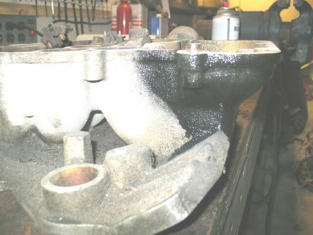
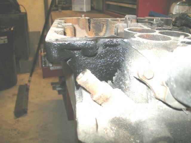
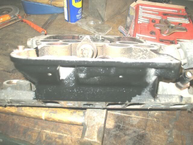
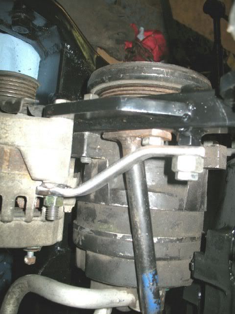
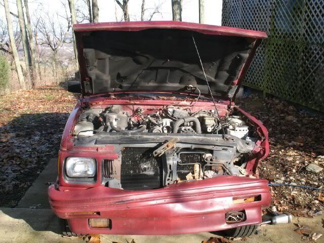
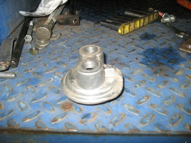
I have not addressed the oil filter relocation setup yet. I am hopeful that I can use the stock 4.3 4x4 relocation setup. I have one, but it is burried inside this:
So the challange for today it to get it out of there and see if it will clear the stater.
IP: Logged
11:22 AM
fieroguru Member
Posts: 12128 From: Champaign, IL Registered: Aug 2003
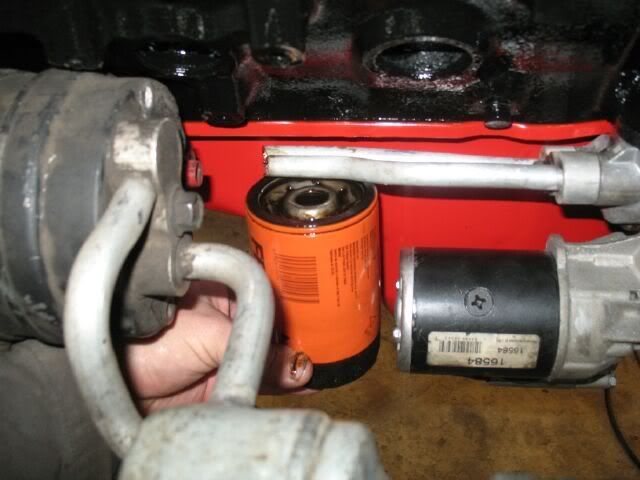
People think working on fieros is tight... These S10 based 4x4's have almost no room. The oil filter bypass probably can not come out in 1 piece without pulling the engine. I cheated by undoing the DS motor mount and raising the engine. This gave the part enough room to come out if I cut the aluminum lines, so out came the sawsall and I got my part!
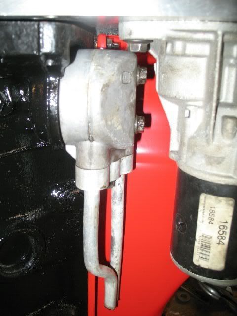
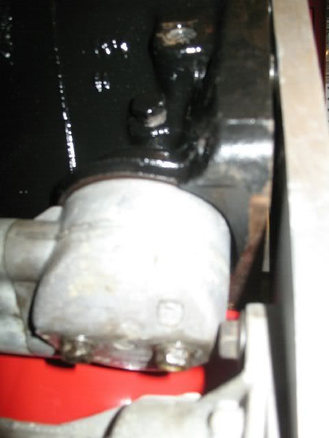
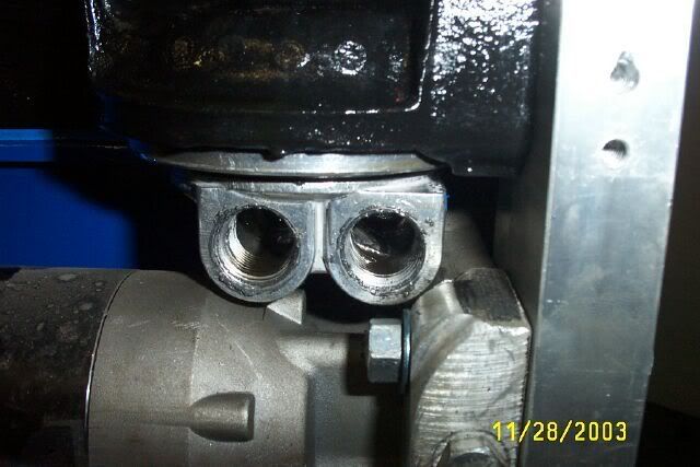
Two steps forward and 1 back. The oil relocation part interferes with the top starter bolt and I can not fully seat the adapter plate.
I could rotate the starter further to make the needed clearance for the starter bolt, but then the solenoid and the main + terminal are getting close to the oil drain plug.
Another option would be to just buy a different bypass that is smaller... I need to sleep on this some. I really like the idea of using the OEM bypass.
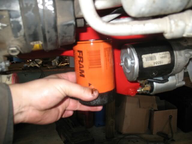
One thing I dislike about my SBC car is that the filters (yes there are 2) are visible. On this swap (because the front cross member is further to the front) there is room to mount the filter between the cross member and the oil pan to the passenger side of the starter and still have 5" of room for the exhaust. I could make a bracket off the lower motor mount stud on the block to hold the filter. I will have to think about this location some more...
IP: Logged
04:04 PM
Dec 30th, 2007
fieroguru Member
Posts: 12128 From: Champaign, IL Registered: Aug 2003
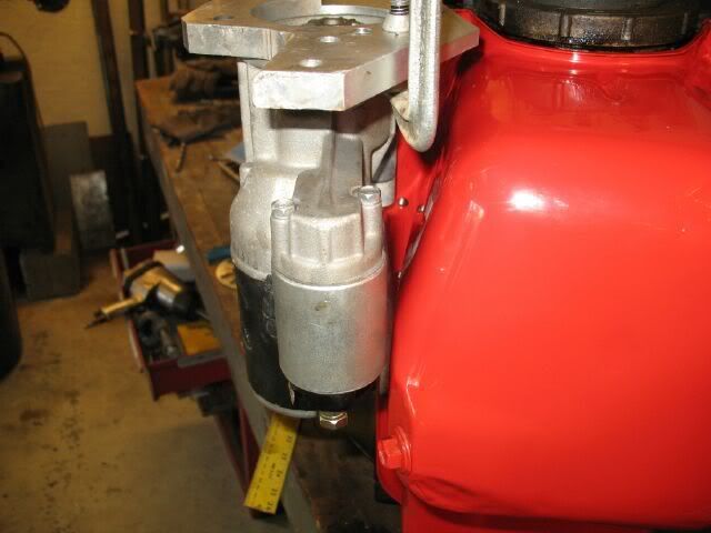
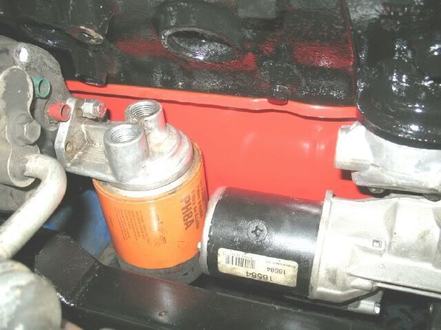
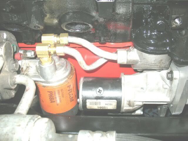
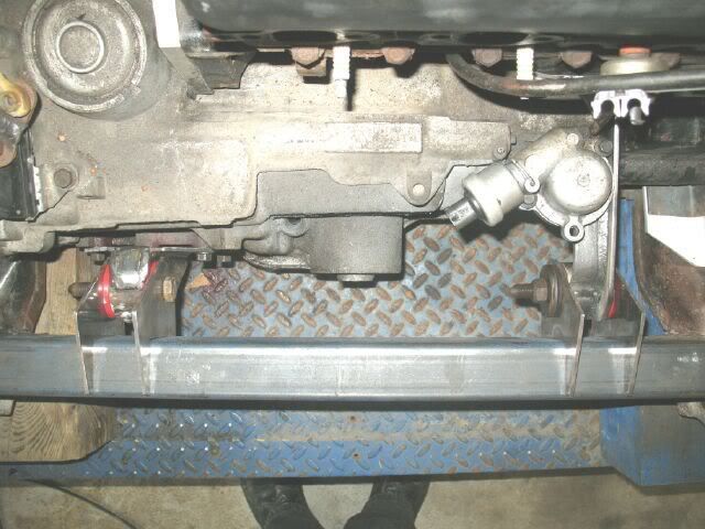
I went ahead and drilled/tapped the adapter plate to rotate the starter to provide the needed clearence to the oil filter bypass. Then put everything back on the cradle to see what could be worked up with the oil filter. With the remote housing bolted to the backside of the AC compressor and using the larger diameter filter (same as my SBC car), everything fits just fine (will have to remove the filter to change the starter, but that is not a big issue in my book). I will probably use hydraulic hoses to connect the bypass to the remote housing.
IP: Logged
10:22 AM
blackrams Member
Posts: 31841 From: Hattiesburg, MS, USA Registered: Feb 2003
Paul, In that you are so gifted in fabrication, was there not an open boss available where the remote filter could have been mounted? Not that there is anything wrong with where you've placed it and I do like the fact that oil changes should be relatively easy and the filter very accessable.
I guess in thinking about it. That starter shouldn't have a need to be removed very often so I guess I agree with it not being a big deal to pull the filter should you need to change out or repair the starter.
Obviously, if I'm doing that much thinking, I need to go work on my own car.
------------------ Ron
It's the Soldier, not the reporter Who has given us the freedom of the press. It's the Soldier, not the poet, Who has given us the freedom of speech. It's the Soldier, not the politicians That ensures our right to Life, Liberty and the Pursuit of Happiness. It's the Soldier who salutes the flag, Who serves beneath the flag, And whose coffin is draped by the flag.
IP: Logged
10:42 AM
vortecfiero Member
Posts: 996 From: Toronto Area, Canada Registered: Feb 2002
Here is the answer I came up with... I designed it and had my machine shop guy make it up it allows positive sealing, allows me to aim the hoses almost any direction and allows proper depth threads.
It is designed to use a hollow bolt from the sunfire etc with an extra o ring. Don't mind the mess lol its been on for 5 years and I was removing it and decided to take pics.
The sensor is for my oil temp gauge.
This was actually the key to my whole install.. I took about a year of figuring till I decided on this route after trying 3 different remote oil adapters.
Im dieing to see your solution lol or copy mine lol
I think Canton or someone now makes them.
------------------
87 Fiero GT 5sp with Vortec L35 4300 Turbocharged V6 Bully Stage 2 clutch Syclone intake manifold and engine management with Moates adapter and chip burner Air/water intercooler and Devil's Own progressive water/alky injection 50lb injectors, 3 bar map sensor, Walboro fuel pump and Jabasco Intercooler pump LM1 wideband on custom manifolds and 3" stainless exhaust system T31/T04B S4 turbo with a Super T61 in the box S10 caliper conversion. Murphy's Constant Matter will be damaged in direct proportion to its value Murphy's Law of Thermodynamics Things get worse under pressure. Arthur C. Clarke "Any significantly advanced technology is indistinguishable from magic"
IP: Logged
11:11 AM
fieroguru Member
Posts: 12128 From: Champaign, IL Registered: Aug 2003
Paul, In that you are so gifted in fabrication, was there not an open boss available where the remote filter could have been mounted?
The remote filter mount flange sticks out a little further than I like, but it is what it is. I did look at having the mount flange up against the block, but then the oil filter would stick out too far towards the crossmember and plumbing the lines into the top would have been slightly more complicated. So I deciced to mount the flange along side the a/c compressor and that bolt hole was just too handy to pass up.
quote
Originally posted by vortecfiero:
Here is the answer I came up with... I designed it and had my machine shop guy make it up it allows positive sealing, allows me to aim the hoses almost any direction and allows proper depth threads.
That is pretty cool and creative. It is similar to the one I used on my SBC but I like that it is bolt attached vs. spin fit:
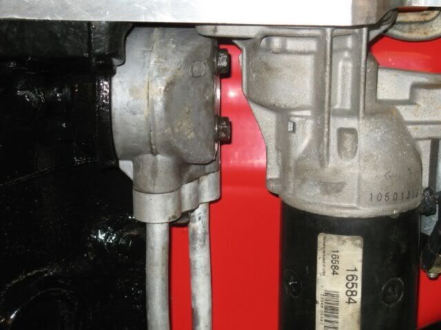
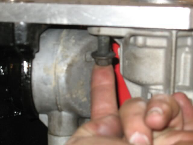
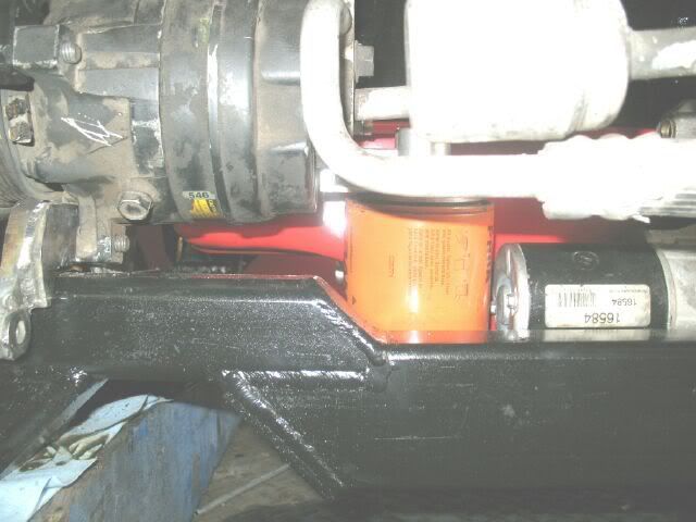
Here is what I have come up with so far. The complication is that the ports from the bypass to the remote mount are flipped from each other requiring the lines to cross over each other. While this should work just fine, I do not really like it and will probably redo it again.
I have another remote filter mount that had the mount bracket cut off. I cut it off several years ago for my SBC swap to allow lining up the lines. If it is installed with the old bracket side to the starter, then the ports would be directly across from each other and 'look" nicer. I would just need to make a bracket to hold it. A piece of angle with two holes where the fittings go in the top should hold it just fine. Then since I would be making the bracket, I could position the filter closer to the AC compressor and eliminate the need to drop the filter to replace the starter.
I was too lazy to mess with firing up the wood burning stove in the garage and now I am too much of a wuss to spend any more time outside. So I will grab the harnesses and lay claim to the kitchen table for some wiring disassembly.
[This message has been edited by fieroguru (edited 12-30-2007).]
IP: Logged
03:33 PM
vortecfiero Member
Posts: 996 From: Toronto Area, Canada Registered: Feb 2002
I am not planning an oil cooler... my SBC does not run one, so neither will this one, but the 4.3 will run synthetic (same as SBC).
Wiring is not my favorite part of the swap (fabrication is my favorite!), but I am very picky about wire routing and too cheap to pay anyone else to do it for me. My method to harnesses (not the fastest or best, but it works for me) is to label everything, remove all pins from the ecm connectors and completely dissassemble the individual circuits. It takes time, but it is how I keep everything simple in my mind. Then I build the new harness 1 circuit at a time routed the way I want it with the focus on minimal wire clutter/chaos.
The stock 4.3 harness is almost entirely disassembled and is currently all over the kitchen floor. One complication was the van 4.3 harness was for a 4T60-E tranny and had quite a few more wires that will not be needed. This also means the Bravada (91 4.3 CPI with 4T60) will lose its ECM shortly. The Fiero harness will go under the knife in the morning.
IP: Logged
09:37 PM
Dec 31st, 2007
fieroguru Member
Posts: 12128 From: Champaign, IL Registered: Aug 2003
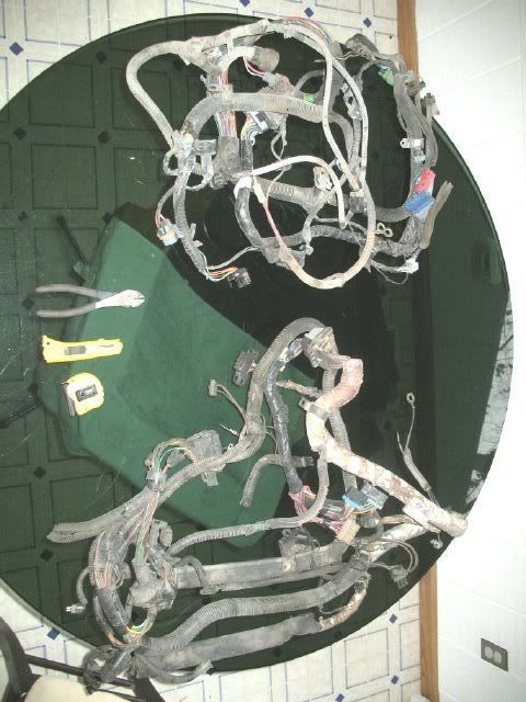
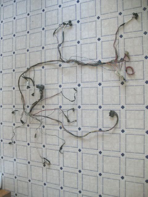
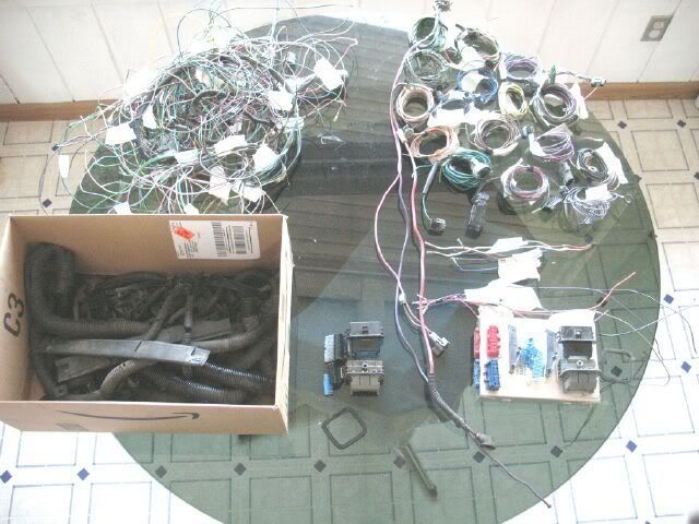
Here is a pic with the Fiero V6 Auto harness on the Right and the 4.3 Auto harness on the Left.
Here is the Fiero harness with all engine related wires removed, but all the non-ECM, auto tranny and ECM feedback wires (like AC - ECM does not control, but likes to know when it is on).
On the right is what is left of the 4.3 harness. All the ECM/Engine wires were broken down into individual/groups of circuits. Some of these will not be reused (like the AC and Fuel pump circuits - exist in Fiero harness and will use those), but they are there just in case I wanted to use their wires. The 4.3 harness came from a Van, so the wires are extra long, which will come in handy. There are also a couple of bundles of wires that go from the ecm to the dash/body of the van (most likely will marry up with Fiero 203 connectors). On the Left is a bunch of wire that was removed from both harnesses and the box of removed wire looms.
While having the wiring fun on the floor my 21 month old daughter learned a new word... messy. "Daddy messy".
[This message has been edited by fieroguru (edited 12-31-2007).]


 certainly nothing that Guru would even concider doing however.