Before I start I want to go through the a check list;
Supernatural 3.4L 250WHP. CHECK
Supernatural 3.4L 300WHP. CHECK
Supernatural 3.7L 350WHP. RUNNING
Supernatural 3.7 9,000RPM. DEVELOPMENT STAGES/LOOK BELOW
Let start shall we!
2.8L piston weight
3.7L 9,000RPM piston weight
2.8L piston pin weight
3.7L 9,000RPM piston pin weight
Supernatural 3.4L piston/rod combo weight
3.7L 9,000RPM piston/rod combo weight
2.8L VS 3.7L 9,000RPM piston comparison
3.7L 9,000RPM rod VS Current Supernatural 3.7L rod Even though the displacement is equally the same the difference in rod size makes for a completelly different application. So that means a completelly different cam and intake combo are required. I'd like to see a vendor offering different cams for two different geometries with the same displacement! They don't have the R&D on the matter.
Have you thought about getting/renting a setup to test engines by themselves out of the car?
Might give more consistent results, removing the variables from the car, and also you don't have to be right next to the engine if it blows up.
Kind of. I'm looking to build an engine break-in chassis for the 60*V6. I don't have patrons or sponsors so if someone wants a specific test to verivy BHP I'll be more than happy to do that for them if they can pay for it plus my R&D time.
When I was going to school for engineering one of my class mates made an engine stand from some square tubing he had laying around. and brought it in for one of our teachers who needed one for a project car. they don't seem that complicated to make if you have decent welding skills as t hey are very basic. the real cost comes from the gauges and the battery needed to make it all work.
When I was going to school for engineering one of my class mates made an engine stand from some square tubing he had laying around. and brought it in for one of our teachers who needed one for a project car. they don't seem that complicated to make if you have decent welding skills as t hey are very basic. the real cost comes from the gauges and the battery needed to make it all work.
Did you dig up a pair of Potter heads? The spring loads required to run at that RPM stand a real chance of popping a rocker boss off production castings.
Did you dig up a pair of Potter heads? The spring loads required to run at that RPM stand a real chance of popping a rocker boss off production castings.
I'll get to that later in the build but yes, I already have that problem addressed; with the iron heads.
I've seen tests that suggest CF and other composite pushrods really aren't good, as they flex way too much, coupled with the leverage of the rocker arm on the pushrod, removing weight there isn't really worth much compared to a lighter spring/retainer/lock and valve.
------------------ "I am not what you so glibly call to be a civilized man. I have broken with society for reasons which I alone am able to appreciate. I am therefore not subject to it's stupid laws, and I ask you to never allude to them in my presence again."
Heads are at the machine shop and the intake drawings at the fabricator.
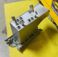
Heads are still at the machine shop but the intake went from mathematical model drawings to reality. Sneak peak of the actual manifold. "Meet The Fogger"!
Before I start I want to go through the a check list;
Supernatural 3.4L 250WHP. CHECK
Supernatural 3.4L 300WHP. CHECK
...
I don't want to derail your new thread, so consider this a request for a Side Project. If you think you can take on this challenge please start a new Thread in TD&Q.
Supernatural 3.4L 250WHP that will pass California Smog Visual Inspection, etc. How's that for an impossible dream?
I don't want to derail your new thread, so consider this a request for a Side Project. If you think you can take on this challenge please start a new Thread in TD&Q.
Supernatural 3.4L 250WHP that will pass California Smog Visual Inspection, etc. How's that for an impossible dream?
I'm pretty sure I can come up with something if I get all the details on how they do yearly inspections. It might take some time but everything is possible if you put your mind to it. But the easy way is turbo charging like everybody else. How do they conduct the inspetions on your Fiero? What's the procedure?
Originally posted by La fiera: I'm pretty sure I can come up with something if I get all the details on how they do yearly inspections. It might take some time but everything is possible if you put your mind to it. But the easy way is turbo charging like everybody else. How do they conduct the inspetions on your Fiero? What's the procedure?
Excellent, thank you for thinking about this. Smog check in the PRC ... someone else will chime in who actually KNOWS the complete picture but I can start with the basics:
1) Smog tech does visual inspection. A turbo would be an immediate fail, as would headers or a different intake or changing to DIS. They are also supposed to look at the Sticker that shows the emission system layout and confirm it has not been altered (e.g. digital EGR wouldn't have the expected vacuum hook up.)
2) They jumper the OBD1 connection and check for codes (I think), which rules out using the better 7730 ECM. Link below explains the digital EGR needed for the 7730 would also likely fail at the visual inspection stage.
3) They then run the engine at 2 different speeds with the sniffer in the exhaust pipe. I believe the speeds are Idle (not to exceed 1100 rpm) and 2500 rpm.
Originally posted by fishsticks: Are you planning on dividing the runners inside the box or just leaving that as one big plenum space?
No dividers, that would defeat the purpose of the plenum. With over 8 liters of volume, the plenum is designed to maximize air pressure abore the runners. The injectors are located on top to add the weight of the fuel to the incoming air to give it more kinetic energy. So when the intake valve opens, there's air pressure and weight to rush in the cylinders even before the sucking action starts by the piston starting the intake stroke. Another bonus of the injectors located so high is that the fuel can absorb the heat of the incoming air cooling down the charge and also the fuel has time to turn into vapor before being injested and that's more power! There is some downsides, less throttle response, on/off throttle like response, but WOT power just seems endless. So basically it is slowing down the velocity of the incoming air. Velocity decreases and pressure increases and viceversa. The intake on my 3.7L is completely the oposite. Either intake combined with the right valve timing, its like having a turbo.
Very neat, would it be crazy to use something like that pre-throttle body? And have individual tall runners post throttle body? That way you get your mixing effects without any sacrifice in throttle response. It would maybe be classified as throttle body injection.
Are the 6 injectors arbitrary at this point? I imagine you could use as few or many as you like. Even could have half of them a different size than the other half if that would benefit you in any way (I’m thinking similar to accelerator pumps in carbs). Probably unnecessary.
No dividers, that would defeat the purpose of the plenum. With over 8 liters of volume, the plenum is designed to maximize air pressure abore the runners. The injectors are located on top to add the weight of the fuel to the incoming air to give it more kinetic energy. So when the intake valve opens, there's air pressure and weight to rush in the cylinders even before the sucking action starts by the piston starting the intake stroke. Another bonus of the injectors located so high is that the fuel can absorb the heat of the incoming air cooling down the charge and also the fuel has time to turn into vapor before being injested and that's more power! There is some downsides, less throttle response, on/off throttle like response, but WOT power just seems endless. So basically it is slowing down the velocity of the incoming air. Velocity decreases and pressure increases and viceversa. The intake on my 3.7L is completely the oposite. Either intake combined with the right valve timing, its like having a turbo.
I have a concern about this arrangement regarding equal distribution of fuel with the injectors so far away from the ports. The closest I have seen to your arrangement with distant fuel injection was on a Formula 1 motor on a race simulated dyno. The difference and point of concern, is the Formula motor ran individual runners with throttle plates and the injectors just above, but very close to the runner inlet, if I recall correctly. Your scenario has air rushing in perpendicular to fuel flow area and I can't help but wonder if that incoming air at higher rpm will displace fuel toward the rear of the plenum. I can't think of an application that has air and fuel perpendicular to each other, prior to the runner entrance.
I recall reading about a tendency of cylinders 5 and 6 to run a bit lean in some of the V6 motors. I'm speculating about the possibility of a ram air like effect forcing more air into those two cylinders, being at the back end of the plenum. The LLT 3.6L DI has a dome in the upper plenum about even with cylinder 5 & 6, I'm not sure why and a 3100 V6 I ran years ago, that I removed due to piston slap, had pistons 5 & 6 in far worse condition than the others, to the point of near failure. It appears your arrangement could do the opposite, run the forward cylinders lean.
Any of those stock GM intakes are designed for packaging purposes, not performace. How much volume do those stock GM intake have? Prolly 1/4 of the displacement. That's why use a massive plenum size. The air velocity slows, increasing pressure and evenly distributing the air between cylinders. If you look at my actual 3.7L I have the TB right at the middle aligning the TB, plenum and runners. Why did I do that? because it is a hi velocity design so distribution is important. When velocity is slowed and converted into pressure, the TB position is more forgiving.
No dividers, that would defeat the purpose of the plenum. With over 8 liters of volume, the plenum is designed to maximize air pressure abore the runners. The injectors are located on top to add the weight of the fuel to the incoming air to give it more kinetic energy. So when the intake valve opens, there's air pressure and weight to rush in the cylinders even before the sucking action starts by the piston starting the intake stroke. Another bonus of the injectors located so high is that the fuel can absorb the heat of the incoming air cooling down the charge and also the fuel has time to turn into vapor before being injested and that's more power! There is some downsides, less throttle response, on/off throttle like response, but WOT power just seems endless. So basically it is slowing down the velocity of the incoming air. Velocity decreases and pressure increases and viceversa. The intake on my 3.7L is completely the oposite. Either intake combined with the right valve timing, its like having a turbo.
You've basically just recreated throttle body injection but with extra steps.
I get what you're trying to do with plenum size vs RPM. I'm concerned you're going to have fuel beading issues though. Smooth wall plenums are generally dry for a reason. What you've created here is a large volume single plane wet intake with extremely short runners. Your injector angle also appears to aim the spray pattern towards the walls of the plenum, which may further exacerbate things. Bead blasting the inside of the box to give some texture may help.
I may have missed it, but is the stated goal to rev to 9k or to make peak power at 9k?
Any of those stock GM intakes are designed for packaging purposes, not performace. How much volume do those stock GM intake have? Prolly 1/4 of the displacement. That's why use a massive plenum size. The air velocity slows, increasing pressure and evenly distributing the air between cylinders. If you look at my actual 3.7L I have the TB right at the middle aligning the TB, plenum and runners. Why did I do that? because it is a hi velocity design so distribution is important. When velocity is slowed and converted into pressure, the TB position is more forgiving.
That makes sense to me. It will require more rpm to elicit the same pressure drop and air velocity at any given point relative to a low volume plenum. Consequently, the lower volume plenum will reach a point of resistance to airflow sooner in the rpm range. You should theoretically have a little slower power response down low relative to the low volume plenum all else the same, but more room to breath up top where the low volume plenum has already started to choke. I still feel the injectors need to be closer to the ports, given their independence from airflow dynamics.
I'm watching you here because I have similar intentions to increase the rpm range of my 3.6L productively beyond the 7k redline, along with other mods, but by optimizing the OE components instead.
[This message has been edited by Joseph Upson (edited 06-07-2021).]
I have a concern about this arrangement regarding equal distribution of fuel with the injectors so far away from the ports. The closest I have seen to your arrangement with distant fuel injection was on a Formula 1 motor on a race simulated dyno. The difference and point of concern, is the Formula motor ran individual runners with throttle plates and the injectors just above, but very close to the runner inlet, if I recall correctly. Your scenario has air rushing in perpendicular to fuel flow area and I can't help but wonder if that incoming air at higher rpm will displace fuel toward the rear of the plenum. I can't think of an application that has air and fuel perpendicular to each other, prior to the runner entrance.
Race engines with injectors above the throttles use "shower" injectors with a wider spray pattern and finer droplet size than production injectors. Production injectors generate much more of a stream than a shower... almost like a messy garden hose. If he has the injectors aimed correctly, most of the fuel is going right down the port.
quote
Originally posted by fishsticks:
I'm concerned you're going to have fuel beading issues though. Smooth wall plenums are generally dry for a reason. What you've created here is a large volume single plane wet intake with extremely short runners. Your injector angle also appears to aim the spray pattern towards the walls of the plenum, which may further exacerbate things. Bead blasting the inside of the box to give some texture may help.
Carbs and throttle body injection use very low fuel pressures and require in-plenum and in-runner mixture motion to achieve atomization and homogeneity of the intake charge. Production port injection puddles fuel on the back of the intake valve and relies on the violence of airflow through the valve to atomize the fuel.
I note that he didn't show the runner entries inside the plenum... for this to work, those have to be carefully radiused and sculpted. They'll also be quite short, but probably not unreasonably short.
[This message has been edited by Will (edited 06-07-2021).]
Carbs and throttle body injection use very low fuel pressures and require in-plenum and in-runner mixture motion to achieve atomization and homogeneity of the intake charge. Production port injection puddles fuel on the back of the intake valve and relies on the violence of airflow through the valve to atomize the fuel.
I note that he didn't show the runner entries inside the plenum... for this to work, those have to be carefully radiused and sculpted. They'll also be quite short, but probably not unreasonably short.
Aware of the differences. Fuel would still bead on and then blow off of a smooth surface, which won't help atomization. Since this thing is called "the fogger" one can safely assume he'll be using wide pattern injectors - probably in batch mode. Aside from air coming through the TB and slamming into a flat rear wall, there isn't much violence happening in that plenum. He's already stated he's trying to decelerate the intake charge to increase pressure/decrease IAT.
If he's got the stated 8L of plenum volume there, my precisely (un)calibrated eyeballs estimate he's using the stock just lower intake tract for runners. So we've got 3" of length or so to work with? (Been awhile since I've looked at a stocker 60* intake).
Originally posted by Notorio: 1) Smog tech does visual inspection. A turbo would be an immediate fail, as would headers or a different intake or changing to DIS. They are also supposed to look at the Sticker that shows the emission system layout and confirm it has not been altered (e.g. digital EGR wouldn't have the expected vacuum hook up.)
Any intake mods are 100% legal. As long as the result has the same features as the original, it passes. Appendix G:
Does not require EO:
Air Cleaner / Assembly –1995 model-year and older without Thermostatic Air Cleaner. Changes are acceptable provided all required emission controls are connected and appear functioning. Intake Manifold2–including diesel air horn or elbow. Intercooler - When Equipped with the OEM turbocharger / supercharger
Switching to digital EGR fails because it modifies the EGR system.
quote
3) They then run the engine at 2 different speeds with the sniffer in the exhaust pipe. I believe the speeds are Idle (not to exceed 1100 rpm) and 2500 rpm.
Depends on where you are. in "Enhanced" areas, which is most of California, they test the car at 15 and 25mph on a dyno. In "Non Enhanced" areas it's just a two speed idle.
If someone made a crazy-ass intake manifold that bolted to the 60*V6 and connected to the factory EGR you could sell it
I don't know whether the factory throttle body must be retained. It's not specifically addressed in Appendix G.
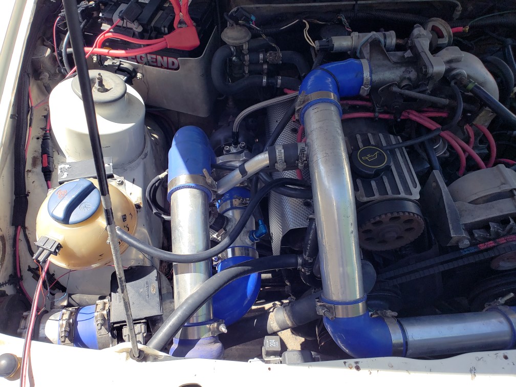
As a visual, this is legal in California:
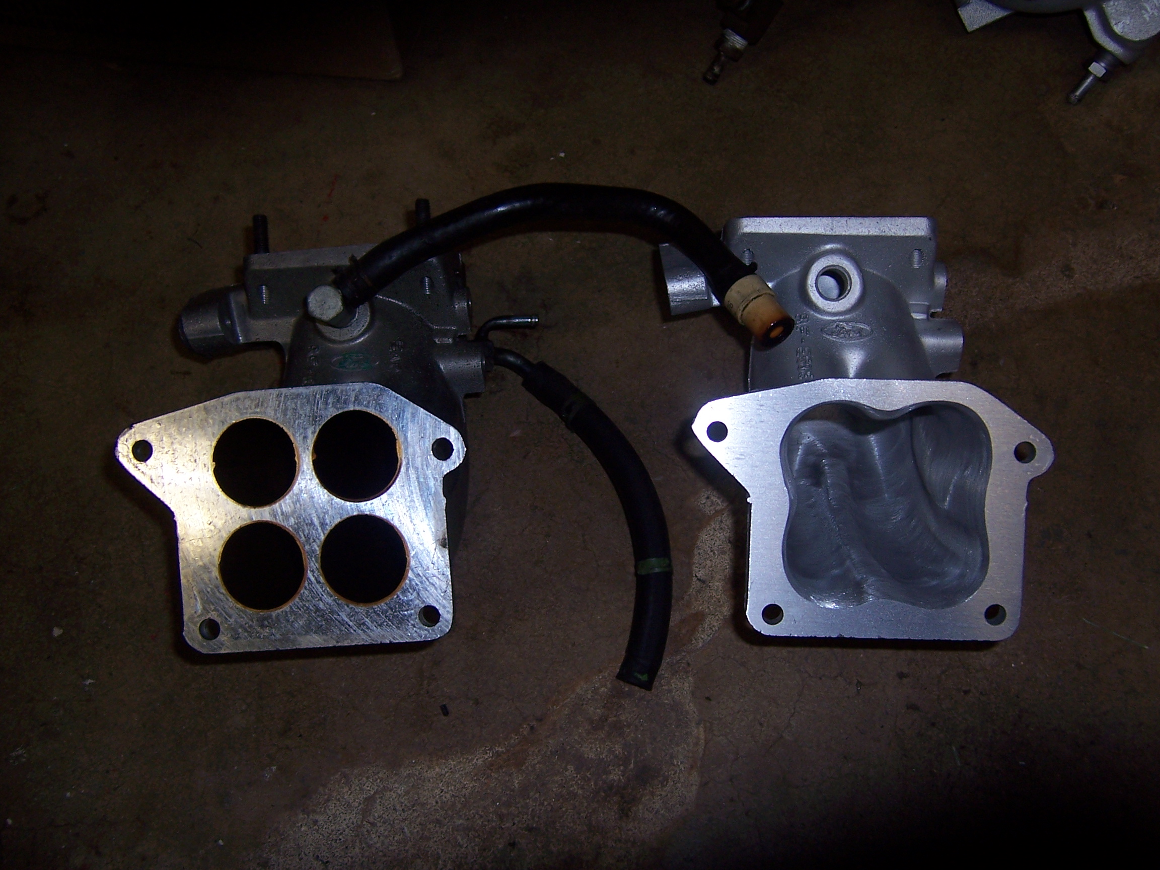
Crazy plumbing, open air filter, giant-ass intercooler, turbo bypass valve. Upper intake manifold is totally gutted, lower is massively ported & knife edged.
[This message has been edited by thesameguy (edited 06-07-2021).]
You've basically just recreated throttle body injection but with extra steps.
I get what you're trying to do with plenum size vs RPM. I'm concerned you're going to have fuel beading issues though. Smooth wall plenums are generally dry for a reason. What you've created here is a large volume single plane wet intake with extremely short runners. Your injector angle also appears to aim the spray pattern towards the walls of the plenum, which may further exacerbate things. Bead blasting the inside of the box to give some texture may help.
I may have missed it, but is the stated goal to rev to 9k or to make peak power at 9k?
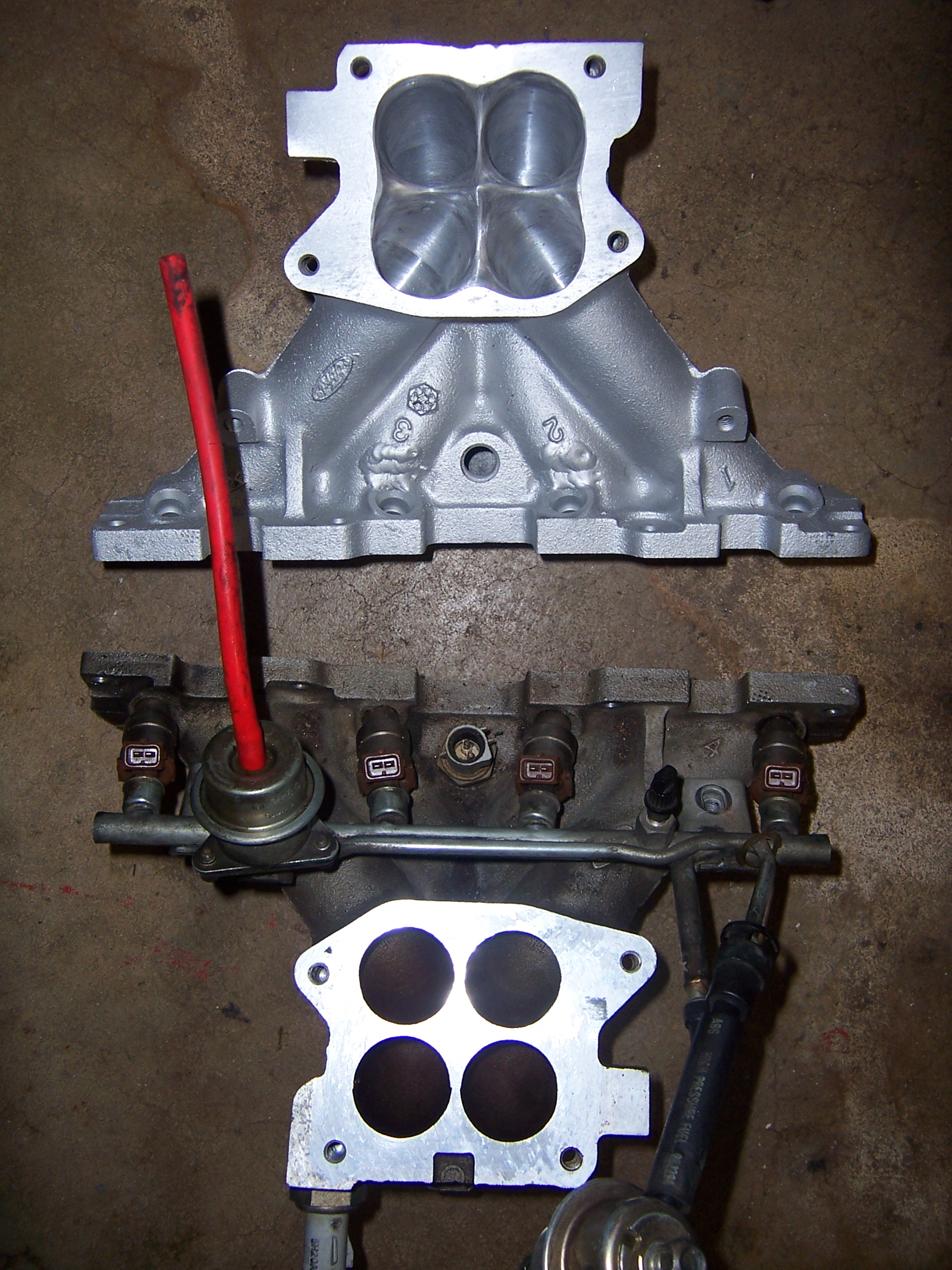
I don't know what injectors are you guys using on your engines but I only use these. Bosch EV1 with 4 hole. The spray pattern is not a "pencil" like the regular Fiero injectors everyone uses. These newer injectors spray like a "fan". With that said, The injector's height is strategically mounted to spray right around the intake valve, not on the stem or the intake walls but exactly in the perimeter of the intake valve.
The injector position is a bit misleading. On the stock Fiero lower plenum the injector in the location of piston #1 feeds that same cylinder. In the picture below the bottom right injector would be cylinder #1 in the stock plenum, on this intake that same botom right feeds cylinder #2. So everyting is backwards. Stock injector order would match firing order but because the are installed higher up the locations are 2-1-4-3-6-5 instead of 1-2-3-4-5-6
9k is the engine redline not the peak power. It'll more between 4000-7500rpms. And that's to keep the engine within the intake and cam timing sweet spot without bogging it down due to the awful throttle response at low end.


 I like Star Treck!