I just finished installing a Vue EPS in my '87 Auto GT. I followed the excellent write-ups on this forum, plus did research on other forums. I used these two threads as my main source of info.
https://www.fiero.nl/forum/Forum2/HTML/138106.html This was a follow up thread on installing the same unit in a Manual Trans car. He had some very good suggestions as well which I combined on my install
The primary differences I incorporated was to do this install without the benefit of lathes, milling machines, etc. Mine was done with the normal array of shop tools, grinders, cut off wheels, die grinder, and a welder. If you don't have a welder, you can follow these threads, and just take your parts to a weld shop . There are a limited number of welds- can probably get them done for $10-$20.
I will break this thread into several posts, as I found out the hard way that one long post can be lost before you hit send
------------------ '87 GT , '00 3800 Series II SC, 4t65e.
[This message has been edited by darbysan (edited 03-05-2017).]
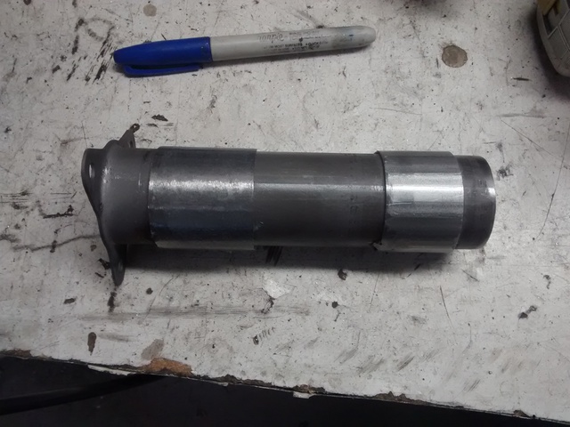
One of the first differences was the dis-assembly of the Vue column. The lower portion, with 3 bolts that attach to the motor, is what is required. Rather than Slicing into the Vue column to get access to this piece, I just knocked it out using a long socket extension . It is meant to slide in the event of a collision anyway, and if the edge you are tapping on gets a little damage, it's no issue to just cut 1/2" off after it is out. You really don't need the entire piece anyway.
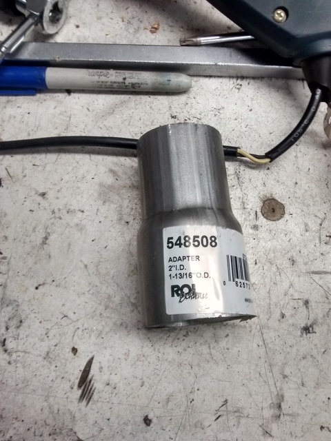
To make it fit inside the FIero column, I used a couple of "slices" of 1 13/16 OD exhaust pipe. It was a perfect fit. I got mine at O'reilly's via an adapter. I find that this particular size of pipe is otherwise very hard to find. I used a coupler, ROL PN 548508 , and just cut a couple of slices off with a reciprocating saw and tacked them onto the Vue piece we just pulled out. Grind the tack welds down so thay do not inerfere with the part sliding into the Fiero column. I found the first "slice" slide right in, but the second one got a little tight. A little light sanding removed some of the manufacturing defects of the exhaust pipe to make it perfectly round. Now you have a connection to the Fiero column that is perfectly centered.
[This message has been edited by darbysan (edited 07-04-2025).]
Next was the Flat plate that attached to the bottom of the column. It has three holes that mate up with the above piece, and a hole in the middle. For the final install, I am going to insert the Vue part in to the Fiero column, so therefore I am using the precision of the Vue part to hold the motor- no need for a precise hole in the plate. I made the plate up using Al's info, and used the VUE column part to locate the 3 bolt holes. These also don't need to be absolutely precise- they are just through holes from the Vue insert to the motor. Follow Al's steps to get the proper motor alignment in the vehicle, then you can mark the plate with the 3 holes and drill. You can also tri-angulate from the three holes to find the center, and then drill a 1.75" hole for the motor to pass through. ( scribe a line from the centers of each hole to the next. Then mark the center of these lines, and scribe a 90 degree line from the scribe mark towards the center of the plate. Do this for all three lines, and you will have a center identified). You can now proceed to welding the plate to the column. The 3 bolts themselves can be a little tight getting installed. Test before welding. IIRC, I had to have one bolt installed through the holes in the Vue pipe and the plate before welding.
[This message has been edited by darbysan (edited 03-05-2017).]
For the upper part of the column, I followed Fiervette's advice. I did not have to machine out the center of the housing nor the plate, and this design maintains the collapsing features of the Vue shaft.
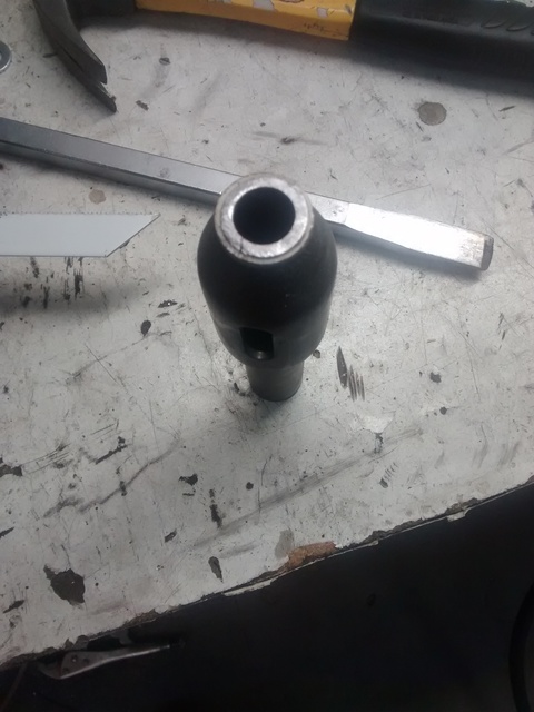
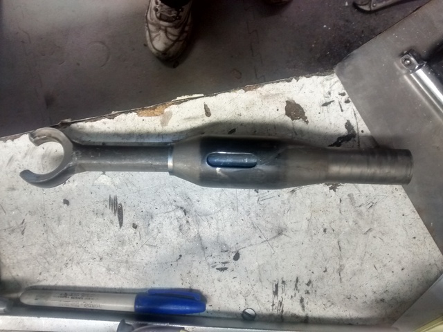
I cut the Vue shaft just above the point where it's expanded area goes back to normal. There is an O-ring groove there, and I sliced through that grove with a reciprocal saw. You are left with a round hole in the vue shaft. This hole is easily modified with a die grinder to a "D" shape to fit the Fiero upper shaft. It is perfectly the correct size for the flat sides of the shaft, so you just have to expand each end of the hole to fit the round sides of the Fiero shaft. You may have a very slight ridge left on the top of the Vue shaft from the o-ring grove. This was a perfect size for the maximum width of the "D" hole. Grind until that groove just disappears, and it should be perfect. Do a lot of test fittings as you go.
Now you can measure the Fiero shaft to determine where to cut. Overall length was as specified by Al68- 8.5" from Fiero flat to end\
Leave you self about 1/2" to slide into the Vue coupler, and cut.
Before you weld VERY IMPORTANT!!. you need to slide the lower housing and the metal plate onto the Fiero shaft before welding. Be sure the plate is oriented in the proper direction . I did a couple of trial "installs" of the lower housing into the column to be sure the holes were properly aligned for the 4 bolts. There is only one way for it to fit! Installation into the column just required a "magnet" wand to help control the metal plate, and a little fiddling to get it to slide into it's place in the column. A few practice runs of this make it easier for the final install.
[This message has been edited by darbysan (edited 07-04-2025).]
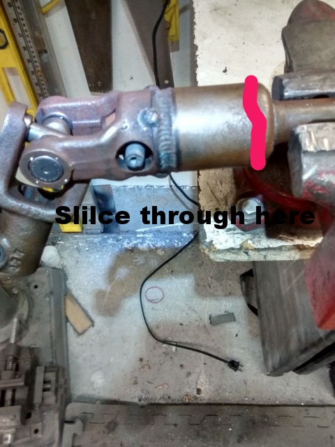
For the lower steering coupler, I used the VUE coupler shaft with the Fiero lower U-joint. I cut both lower u-joints off, and then welded the Fiero u-joint to the Vue shaft. Overall length was 19.5". Keep both u-joints in the same orientation.
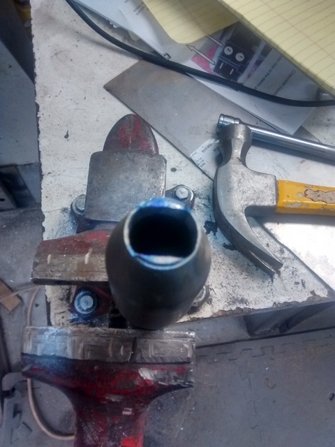
If you "slice" through the outer portion of the Fiero U-joint, where I have the red line marked, you will find the inner portion is filled with rubber.
Once the outer portion is sliced, the Fiero shaft will just pull out ( with some effort). Don't forget to first drive out the Roll Pin in the shaft. You can then dig out the remaining rubber from inside the Fiero U-joint. I found in my scrap pile a piece of pipe that would just fit inside the Fiero U-joint, and the ID of this pipe was just the right size for the round Vue shaft to be installed. Gave me an easy way to reduce the Fiero u-joint to match up with the Vue column connector.
On the Fiero, the bolt for the lower u-joint was vertical ( head at 12 o'clock) when the wheels were straight ahead. I welded the shaft so that the Vue bolt was also vertical, but with the head at 6 o'clock, for ease of install. The Vue shaft slides on grooves, and it looks like the shaft was heat treated after assembly to create 2 "hot Spots" that restrict the ease of the shaft sliding. It can be moved, but it does require some force. This was probably one of the harder parts of the install- getting the shaft onto the end of the motor and onto the Rack and Pinion. I eventually pulled the 4 bolts holding the rack to give me some wiggle room. No problem with alignment- just bolt the rack back on.
[This message has been edited by darbysan (edited 07-04-2025).]
I remote mounted the control box ( and the Ebay Controller) in the Front trunk, mounting them on the driver fenderwell next to the booster. Mount it low, as the hood can be an interference. I have a front mounted battery, so power was easy for me. For ground, I used one of the Brake Booster bolts.
I wanted to be able to remove the steering column / motor as an assembly, so I needed a connection for high power at the motor. I found this connector on the web, and it worked great. It is only a 50 amp connector, and the fuse on the motor is 80 amps, but I felt it would be sturdy enough as the motor usually never draws more than 20 amps. It is a 50 amp Battery Disconnect used for trailers or winches. I used 8 Ga wire to connect from the controller to the connector inside the car.
I used a 4 pin weatherpak connector I had in my scrap pile to connect the Control box to the Torque sensors at the motor.
The controller I used was one sold on Ebay by Bruno ( Portugal). He's sold a bunch of them, and is the "expert" on this mod. He was also very helpful in answering several questions I had. The controller comes in two versions- one with a Pot you adjust, and the one I bought which was "automatic". When I got mine, I found it has one wire from the controller that is either Grounded ( low), open ( Med) or Grounded with 100K resistor ( high). I had a place for a three way switch, so I installed it so I could test the different settings. I find that the lowest setting seems a good one for me. It still gives plenty of road feel, and is not even noticed at hwy speeds. In the parking lot, it makes maneuvering very easy- one hand easy. The med and high settings are noticeably different, but not enough that it's worth the difference, or worth adding a switch if you were not already set up like I was. I would recommend just buying the one with the pot, and setting it and forget ( $10 less).
Driven it a couple of hundred miles now, and so far I like it. Very satisfied with the results. One recommendation would be to "clean" the motor before install, as it is a known trouble spot. Here's a link to a thread for that. http://www.redlineforums.co...ix-pwr-str-step.html
[This message has been edited by darbysan (edited 03-05-2017).]
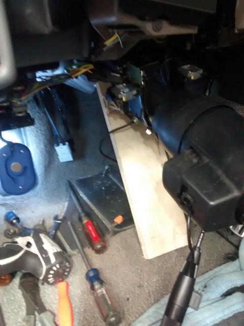
The hardest part of this install was getting my old, fat body to work under the dash. It got even harder trying to install the column with the motor attached, as the weight of the motor wants to torque everything towards the left. I finally made up a tool to help me install, from a piece of scrap plywood. I use it to support and wedge up the motor end of the column. I put the steering wheel nut on the column, locked the wheel via the key, and then used the nut with a long socket wrench ( breaker bar would also work, to help counter the torque as I shoved the completed unit into place.
Note that the end of the column shaft should have a "notch" in it, like a chisel strike. This was made at the factor to signify straight ahead when the wheel is installed. Use this notch, along with the key to lock the column in a straight ahead position for aligning the lower steering connector to the vue motor shaft.
[This message has been edited by darbysan (edited 07-04-2025).]
Created a public link ( I hope) for the pictures...
Yes, the images are downloadable.
Since this thread is not archived, it means your posts can still be edited. If you feel so inclined, it would be great if you used the Upload Media tab (not PIP) to replace the missing images within your posts.
[This message has been edited by Patrick (edited 07-03-2025).]
i didn't agree power steering was necessary but i went through a tight roundabout this week and wished i had a steering box with less end to end turns.
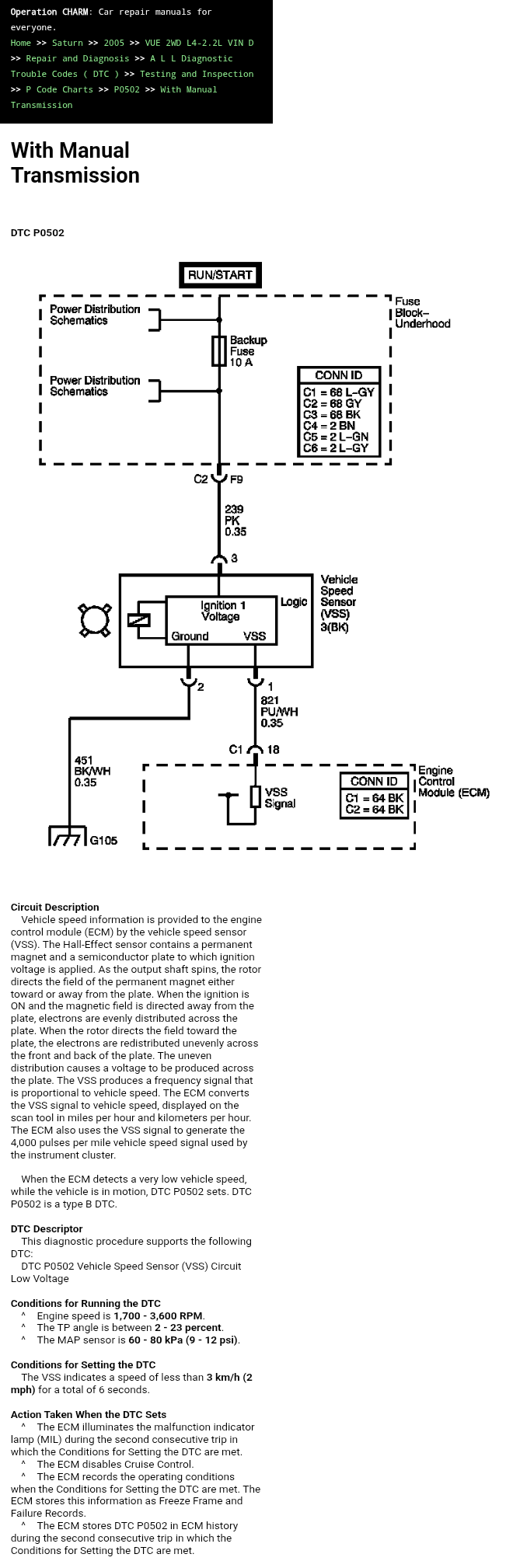
I was thinking about how you would wire this into the Fiero so you don't have to get a control module from that seller on eBay, while it's cool that it can be controlled with the knob, or the automatic module, or the GPS version, I think it would be best if it operated off the car's VSS signal so it's altering the power assist according to the car's speed in a self contained system.
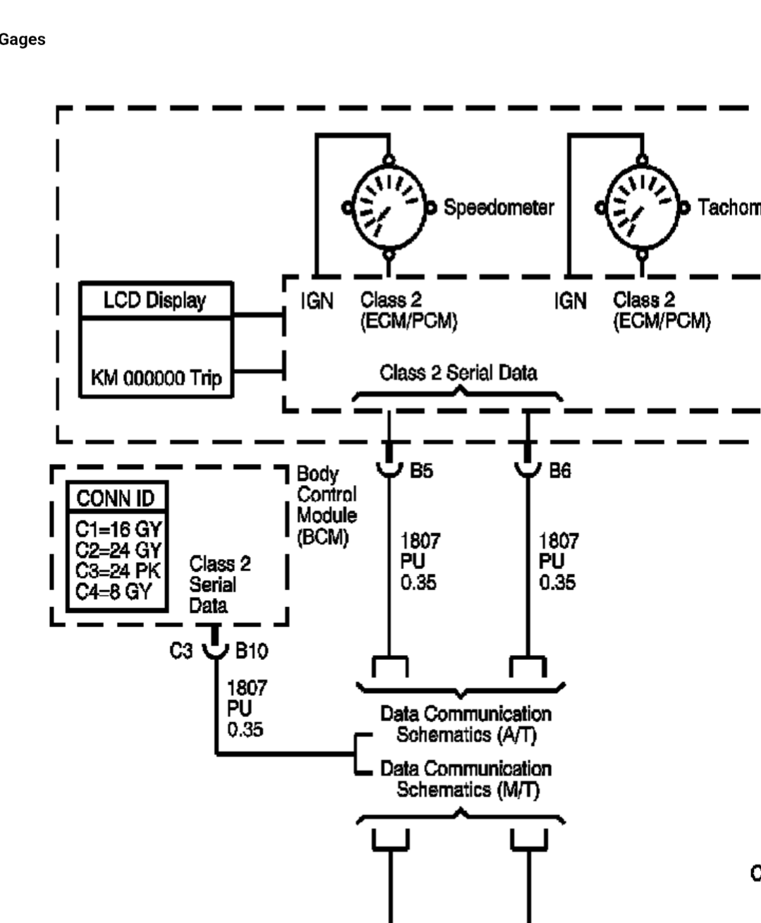
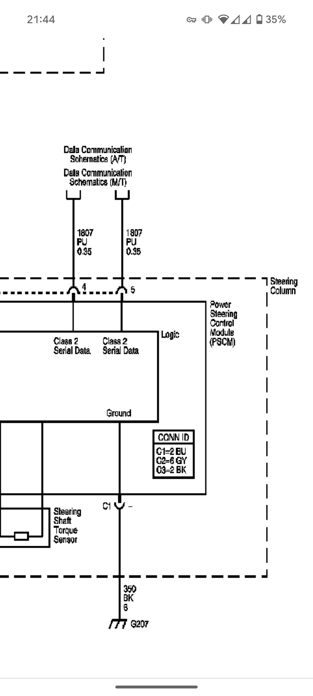
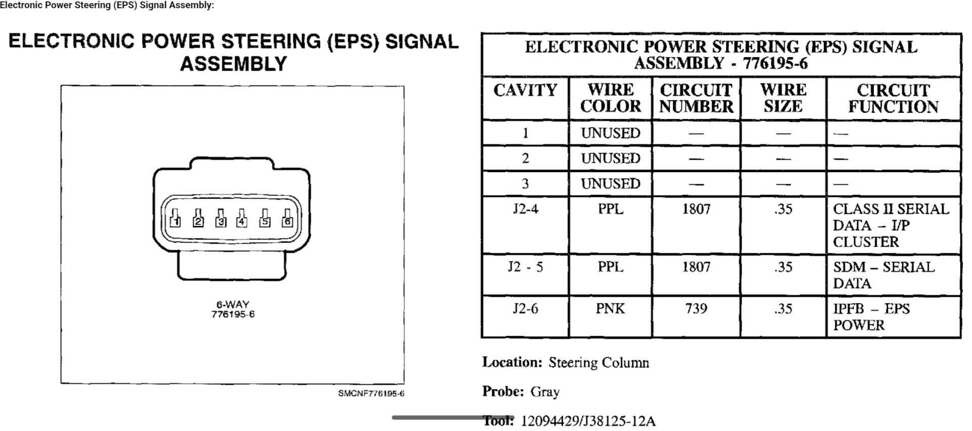
The Fiero can put out a 4000 PPM signal from the 88 speedometer on pin M(?) from my research or you can use the third gen FBody buffer box like the Firebird cluster swaps, and after some exhaustive research it appears that the Vue also uses a 4000 PPM signal. Here are the references and you should be able to hook in the signal wire to pin 4 on the Vue's connector to get the proper speed signal.
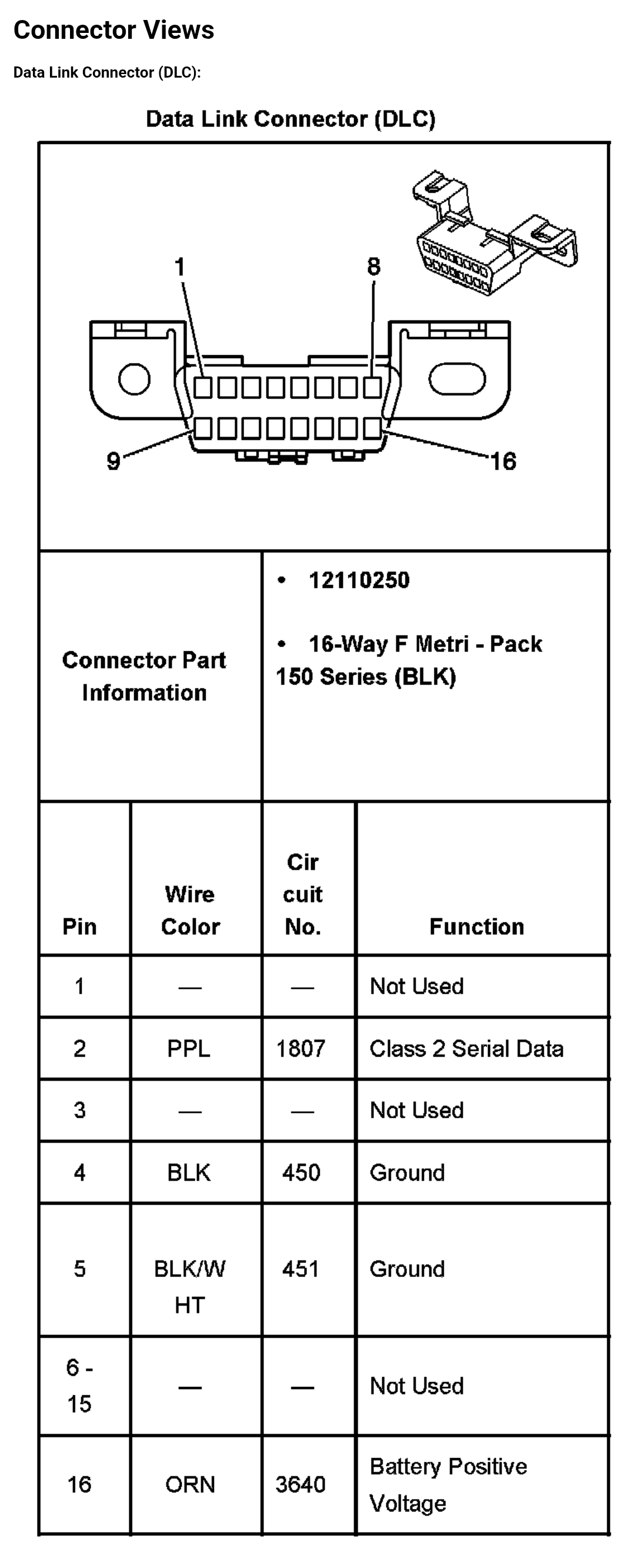
Also connect the wire from Pin 2 on the OBD2 port to Pin 5 on the EPS unit if you have an engine swap it looks like, same circuit.
[This message has been edited by rbell2915 (edited 07-16-2025).]