I'm in the process of building my harness for my 3800SC swap into my 88GT and I have the prints, etc. from Ryan for the electronic cruise control portion of the swap. Here is my question which I know many of you have already done. Do I need to run the two wires from C1-72 (dk grn cruise inhibit control) and C2-59 (wht cruise control status) from my PCM to the rear compartment location of the existing OE servo connection or is there another place internally of the car to splice into? I cannot determine this from my service manual. Also how many have done this conversion to stock vehicles vs. just during engine swaps?
Yes you need the 4000 PPM output to be bridged to both the speedo (high) and the cruise input for automatic transmission or later model manual transmission applications. The 4000 PPM output needs to run through a speedo buffer http://www.reddevilriver.com/Related_Products.html
For a Fiero manual transmission you can run the VSS to both the speedo and PCM. Then the only thing connected to the 4000 PPM output goes to the cruise control.
You can run the cruise inhibit lead to the PCM if you wish to. You can also just ground it. The idea of the cruise inhibit is so the PCM can enable and disable the cruise depending on speed and conditions. If you run the lead to the PCM then also make sure your PCM is properly programmed for the correct 4000 PPM (ish) input. The stock AT VSS or later model MTs have a 24000 PPM output.
You need both brake inputs for the cruise control to work. One (C) needs to be +12 at idle, and the other (G) needs to be +12v with the brake applied. You can not hotwire these inputs because the cruise looks for them to change states at least once before it will start to function.
You can use the cruise engaged output to light a light on your dash if you wish.
I have had some issues with some of the GM electromotive cruise control units (even those marked "AR") in Fiero swaps not wanting to engage at all. This is when they are NOT connected to the PCM on the cruise inhibit and status circuits.
I believe the problem is some of these cruise control modules want to see the cruise inhibit input change state at a certain speed (perhaps?) and that won't happen if you just ground that wire.
If you are using a manual transmission in your swap, the PCM may never ground the cruise inhibit wire to enable cruise operation because there is no electronic auto transmission present.
Since the discovery of this problem, I have been building my stockpile of 96-99 Cadillac Northstar cruise control modules (they look identical to the ones used on the 3800s; except the Cadillac ones are marked "V8"). Every single 96-99 Northstar cruise control module I've gotten from a Cadillac has worked fine without having the cruise inhibit and status wires hooked up to the PCM. All you'll need to do is permanently ground the cruise inhibit input to the cruise module.
Cables can be easily swapped out on these cruise modules so you can use any cable you need to match your throttle body.
-ryan
------------------ OVERKILL IS UNDERRATED Custom GM OBD1 & OBD2 Tuning | Engine Conversions & more | www.gmtuners.com
I'm having this problem with my 3800 swap with the AR cruise control module, it won't work at all, have tried 2 different "AR" modules. I get nothing when trying to set the cruise at any speed.
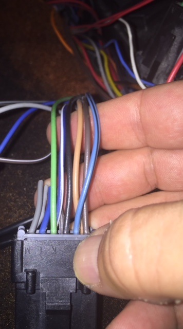
Gray – You should have voltage on the gray wire anytime the cruise control switch is in the on position
Dark Blue – You should have voltage on the Dk. Blue wire when the set button is depressed
Gray/Black – You should have voltage on the Gray/Black wire when the Resume/Accelerate button is depressed.
Brown/White – You should have voltage on the Brown/White wire when the cruise control is turned on. The voltage should drop to zero when the brake or clutch pedal is depressed. If not check the brake/clutch switches.
If you have no voltages on any of the wires, check the clutch and brake pedal switches with the yellow wires on them. With both pedals (or one if auto) the switches should be depressed and +12 should be present on both sides of the switch (key on).
Pink - You should have +12v on the Pink wire when the key is on.
White or Lt. Blue wire – Connects to either the White or the Lt. Blue wire at the brake switch. This wire should have power on it whenever the brake pedal is depressed.
Pink - You should have +12v on the Pink wire when the key is on.
White or Lt. Blue wire – Connects to either the White or the Lt. Blue wire at the brake switch. This wire should have power on it whenever the brake pedal is depressed.
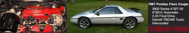
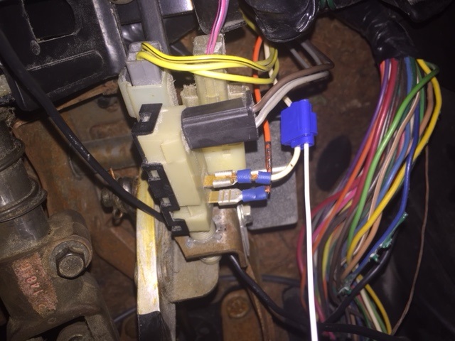
Anybody know where this 3 plug connector is located? I don't see it at my brake switch.
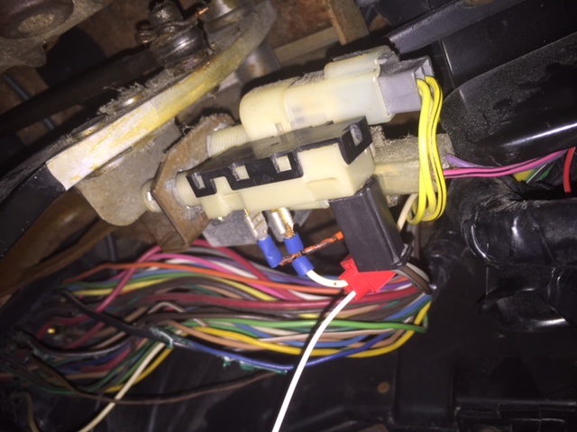
I am supposed to be seeing this right? This pic shows the Lt Blue, White, and Pink wire:
Take a 12v test light and connect it to ground and put the probe on the white wire shown in your pic. That would be next to the orange wire. The white wire I am looking at in your pic has a slide on terminal crimped on it. It looks like someone made some mods to your brake switch, but the white wire should be the one you are looking for. You will know it's right if you get voltage on it when, and only when the brake pedal is depressed. I think you will find you have power all the time on the orange wire.
If you have power on the white wire when it is depressed, then it is the right one.
Thank you Tim! In your email you mentioned that I was supposed to look for a white wire next to Pink (not orange) and Lt. Blue like in the picture...that's why I wasn't sure if I was pointing to the right connector in my pic.
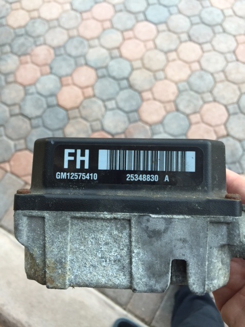
I am installing a digital cruise control servo into my L32 3800 (2004 Grand Prix GTP) 4T65E HD Fiero.
I would like to confirm that the servo I am using (seen below) is in fact compatible. I believe it to be, but because it is labeled "FH" and not "AR" and apparently from either a 2002-2005 Buick Rendezvous CXL or a 2001-2005 Chevy Venture, Pontiac Montana/Aztec or Oldsmobile Silhouette, I wanted to confirm.
Does anybody know the difference between the FH and AR modules?
Thanks, -Van
[This message has been edited by VanGTP5000 (edited 02-11-2018).]
Take a 12v test light and connect it to ground and put the probe on the white wire shown in your pic. That would be next to the orange wire. The white wire I am looking at in your pic has a slide on terminal crimped on it. It looks like someone made some mods to your brake switch, but the white wire should be the one you are looking for. You will know it's right if you get voltage on it when, and only when the brake pedal is depressed. I think you will find you have power all the time on the orange wire.
If you have power on the white wire when it is depressed, then it is the right one.
Tim,
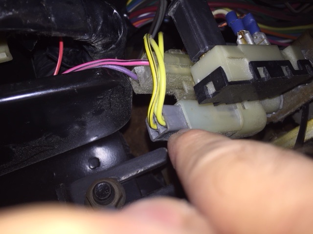
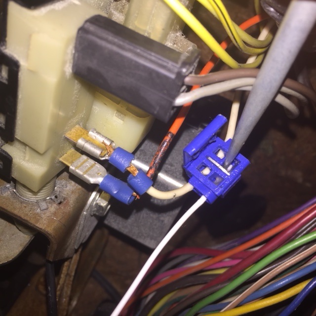
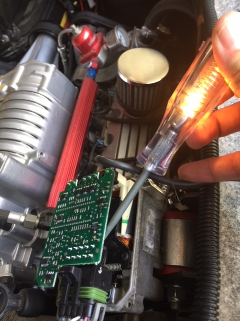
The white wire functions just as you said. Orange = power full time, White only when brake is depressed. So I quick spliced the long White wire from your harness into the White wire on the brake switch as seen here:
The light in this picture is provided courtesy of the test light probe touching the connection while depressing the brake. I would think that means that the long white wire is getting the right signal and functioning properly.
However, I can not get any voltage on the Brown/White wire when I turn on the cruise control switch. Every other wire function tests positively. I know you mentioned in your email to me (and in the instruction page you sent me) to check the brake switch if this is the case. I have, and it appears to be functioning properly. I assume this must be a common problem. What should I be looking for in this case?
Any help will be much appreciated.
-Van
[This message has been edited by VanGTP5000 (edited 02-18-2018).]
Sorry for the slow reply. There are two switches on the brake pedal that affect the cruise. One is the white wire that gets +12v when the brake pedal is depressed. The other is the Brown/White wire that gets power all the time (key on) except when the brake pedal is depressed. Why the two wires with the opposite functions? The two switches give redundancy to the brake to cruise control connection. If both don't cycle on/off the cruise won't engage.
Does the connector right next to the one you are working on have a gray and a brown/white wire? If so does the gray wire have +12v on it all the time and the brown/white have +12 on it when the brake pedal is at rest (key on and cruise on). It should.
The gray wire gets its power from the cruise switch. That is also the gray wire that extends all the way to the cruise. It should have power anytime the cruise is on. If you are not getting power on the gray wire look at the cruise switch being bad.
Oh ok. I was testing for power in the wrong spot! I had been testing at the point where I spliced your Brown/White harness wire into the old Brown/White wire of the Stock Fiero cruise control plug and wasn't seeing any power there.
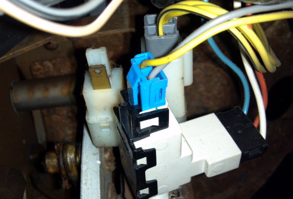
As can be seen in the pics above...the brake switch where the black connector is has two Gray wires and one Brown wire (I don't see a White stripe) leading into it. I just tested for power and the test light does show power when the Cruise switch is turned on (key on) and is interrupted when I depress the brake pedal.
If I re-pinned the Original wiring harness plug pin that came loose from the servo plug correctly, I think it should work. I can't wait to test drive and see.
I came home early to do a test drive of the cruise control. It didn't work. I have checked all the wiring connections.
Recap:
New Cruise Control Stalk installed.
Brake switch connector: Orange wire has power full time (key off). White wire has power only when brake pedal is depressed (key off).
Brake switch black 2 prong connector: Two Gray Wires have power (key on, cruise on). Brown wire (I don't see any White stripe on it) no power any time.
There is power on each spliced connection at the Stock Fiero plug wires to the new harness wires with the only exception being the Brown/White wire. No power is detected. The same applies for the end of the harness plug that connects to the plug at the ECU. There is power on each pin of that connector except for the Brown/White pin and the White wire pin next to it.
There is only power at the harness plug that connects to the FH digital servo on the Pink wire (key on) full time, Gray wire (key on, cruise on), Gray/Black (key on, R/A on), Dark Blue (key on, set on).
I unplugged one of my LED tail lights and put a regular incandescent 1157 back in thinking that maybe I may have a problem with not having a relay installed, but it didn't solve the problem either.
I am stumped.
-Van
[This message has been edited by VanGTP5000 (edited 02-20-2018).]
So the no power on the brown wire appears to be the problem. Of course the switch has a function and since it has power on the gray wire (that turns off when the cruise on the stalk is turned off right), this is the switch contact in question. So why doesn't the switch close when the pedal is in the idle position? Perhaps the plunger isn't fully depressed by the pedal because of the adjustment of the switch. Try manually pushing the plunger into the switch body a little more and see if that gives you power.
Perhaps the switch is bad.
Perhaps the switch is just the wrong switch. But the contacts should close at some time, either with the plunger all the way in or with the plunger all the way out. That is what a switch does.
You did check for power on that brown wire with the key on, cruise on, and the connector plugged into the switch correct?
--------- White pin - You do have to get that going all the way to the cruise also before the cruise will work. Check it at the connector by the PCM. Perhaps I pinned it one off. Make sure you are getting power on the white there when the brake pedal is depressed. Make sure when the plugs are mated the white wire is passing through. The white wire then runs continuously all the way to the cruise connector.
Get the Brown/White wire working correctly and get the White wire working correctly and the cruise should work.
[This message has been edited by phonedawgz (edited 02-20-2018).]
The schematic I sent you shows all the states you should see at each pin at the cruise module connector as you cycle the components of the system. If all those check out, swap out the cruise module. I went through 3 AR modules before I found one that worked (nothing changed in the wiring, just some worked, others didn't).
I will keep in mind that the Servo may need to be replaced. I saw on your wiring diagram that my servo part # 25348830 FH unit isn't mentioned. I am still not sure if this is even compatible with this application.
Part of the problem now is that when I went to pull the harness plug from the servo, I lost power on the Pink pin which was functioning earlier in the day. Upon further inspection I realized that the crimping job I did on the Delphi 150 Female terminal without a proper crimping tool didn't hold. So I am right back where I was in this thread:
So the no power on the brown wire appears to be the problem. Of course the switch has a function and since it has power on the gray wire (that turns off when the cruise on the stalk is turned off right), this is the switch contact in question. So why doesn't the switch close when the pedal is in the idle position? Perhaps the plunger isn't fully depressed by the pedal because of the adjustment of the switch. Try manually pushing the plunger into the switch body a little more and see if that gives you power.
Perhaps the switch is bad.
Perhaps the switch is just the wrong switch. But the contacts should close at some time, either with the plunger all the way in or with the plunger all the way out. That is what a switch does.
You did check for power on that brown wire with the key on, cruise on, and the connector plugged into the switch correct?
--------- White pin - You do have to get that going all the way to the cruise also before the cruise will work. Check it at the connector by the PCM. Perhaps I pinned it one off. Make sure you are getting power on the white there when the brake pedal is depressed. Make sure when the plugs are mated the white wire is passing through. The white wire then runs continuously all the way to the cruise connector.
Get the Brown/White wire working correctly and get the White wire working correctly and the cruise should work.
Phonedawgz,
I gently moved the brake switch into a better seated position and now the 2 Gray wires function as they should along with the Brown wire functioning properly at the switch location.
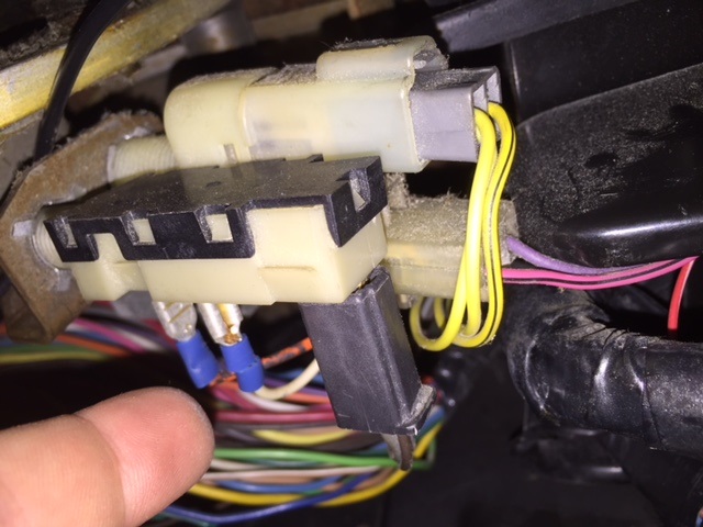
I am still not getting any power on the Brown/White wire from the Stock Fiero plug. I should see power on this wire full time (key on) until brake pedal is depressed correct? I think I may test the other wires to see if maybe I am working off the wrong wire. I did use the Brown/White stripe wire (seen by my index finger in pic) but maybe one of the others will work.
I did, however solve the White wire problem. It turns out that my Blue quick splice was one size too big for that tiny White wire. I replaced it with a Red quick splice and it penetrated the White wire insulation properly this time.
So now all wires function at the pins of the harness plug to be connected to the servo with the exception of the Pink wire which I just need to re-pin again and the Brown/White wire.
It turns out that the Brown/White wire was not the right wire after all. I cut and spliced in the Brown Wire to the far right of the Stock Fiero cruise control plug seen in the pic above and now I see power (key on, cruise on) until brake pedal is depressed.
All that is left now is to get a crimping tool that can handle the one lone Delphi 150 Female 18-16ga terminal I unsuccessfully crimped using a standard pair of pliers. It held and worked initially, but didn't stand up to the rigors of pulling the plug from the servo a few times for testing.
I haven't found one that is under $130 yet! If anyone knows of one please let me know.
Thanks, -Van
[This message has been edited by VanGTP5000 (edited 02-22-2018).]
Pull the pin out of the connector, slide the seal up on the wire and then slide the terminal on. Then solder the terminal on the wire and slide the seal back up in place. A pita but for just a single terminal not a problem.
Pull the pin out of the connector, slide the seal up on the wire and then slide the terminal on. Then solder the terminal on the wire and slide the seal back up in place. A pita but for just a single terminal not a problem.
I woke up to a phone call from EFI Connection in Pa this am. He confirmed that the prices I had seen on their website do cause sticker shock in most novice people like myself. He went further to explain how each terminal has factory specs that require proper clearance for each jig made to consider air clearance and depth and height requirements of the actual crimp of the terminal created by the tooling. He had said that the Radio Shack type was not suggested because of that fact. I interrupted him to explain that I was crimping one lone terminal and his response was similar to your own Tim. He said, "Just solder the connection making sure to avoid getting any solder in the path of the locking tab." I was told to do this same solder "deal" initially when the problem first presented itself a while back but typical of me...I just had to try and do it the way I thought it was supposed to be done correctly. Without the proper tool I failed.
Thanks for the follow up Tim. I will give the solder trick a try.
-Van
[This message has been edited by VanGTP5000 (edited 02-22-2018).]
I rushed home to re-pin the errant wire tonight. Mission accomplished. Tested the pin at the plug with a test light. Tested all the pins at the plug for that matter and they all seemed to be functioning correctly as I cycled through the cruise stalk functions. So I plugged it in, Jumped in the car to test drive it. It didn't work. Now I suppose it is possible that I have a faulty cruise servo as fieroguru had mentioned. But I went back into a thread that I started https://www.fiero.nl/forum/Forum2/HTML/140891.html and found this post from Spoon:
quote
Originally posted by Spoon:
VanGTP5000,
Don't take this as gospel but here is a note from my schedule dated July 11, 2011 when I was installing digital cruise control. My car had existing CC and it is a 4 spd /2.8. **** FIERO / REWIRE CRUISE CTRL BRAKE INPUT UNDER CONSOLE. SERVICE MANUAL SHOWS BRN/WHT WIRE FOR BOTH BRAKE INPUT AND VSS INPUT. ACTUALLY A SOLID BROWN WIRE IS FOR THE BRAKE INPUT (KEY ON - RUN). THIS GETS CONNECTED TO THE TAN WIRE AT SAME CLIP. THE SINGLE BRN/WHT WIRE IS FOR VSS INPUT.
Spoon
I had no power from the Brown/White stripe wire, but when I spliced in the solid Brown wire it performed properly when I cycled though each of the stalk functions. Yet the cruise control still doesn't work. I thought that switching over to the solid Brown wire would solve my problem but it didn't. Am I using the wrong wire even though it has power (key on, cruise on) until brake pedal is depressed?
If all the wires are functioning correctly, but the cruise control still doesn't work, then I am going to say the problem resides with the cruise servo. I can send you one that is known good if you want.
If all the wires are functioning correctly, but the cruise control still doesn't work, then I am going to say the problem resides with the cruise servo. I can send you one that is known good if you want.
Well that seems to be the case here. It is possible that the board has gone bad because power coming in on each of the pins test fine.
Please let me know what you have in terms of a replacement Tim.
Thanks, -Van
[This message has been edited by VanGTP5000 (edited 02-25-2018).]
I just installed yet another cruise control servo. This time it was the "AR" instead of the "FH". It didn't work either. I don't understand what is wrong. All wiring tests properly with a test light at the plug that goes into the servo. Is there a way to diagnose this problem other than continuing to waste money buying used cruise control servos? Buying a new one is not an option for me at the current prices.
If anyone can help or has a suggestion, it would be greatly appreciated. I am pretty frustrated at this point.
-Van
[This message has been edited by VanGTP5000 (edited 03-02-2018).]
3rd module was the charm for me. Installed the 3rd and it just worked after the first two refused to work. I didn't change a thing with the car or wiring.
Have you measured the resistance values on the two wires that switch from +12V to ground. Darth specified that they need to have a pretty low resistance value (something like 20 ohms) to ground. He also commented about having several modules that would never work in the Fiero (when others would work in the same car), but worked just fine in a factory GM installation in a FWD car. The cruise module use and function isn't as consistent as it should be for some reason.
I remember reading that some modules need to see the Cruise Inhibit wire to ground, while others preferred it to be left open. That's pin H, Dk Grn at the module. Something to try. Also remember the LED taillight issue. That definitely requires fixing to make the module work.
He also commented about having several modules that would never work in the Fiero (when others would work in the same car), but worked just fine in a factory GM installation in a FWD car. The cruise module use and function isn't as consistent as it should be for some reason.
I was unaware of this. Is there a list of these modules out there somewhere? Or better yet...is there a suggested particular module that works more often than not?
quote
Have you measured the resistance values on the two wires that switch from +12V to ground. Darth specified that they need to have a pretty low resistance value (something like 20 ohms) to ground.
I have not measured resistance on any of the wires. What color wires are the two you suggested?
I remember reading that some modules need to see the Cruise Inhibit wire to ground, while others preferred it to be left open. That's pin H, Dk Grn at the module. Something to try.
Does that mean I should try and pull the terminal pin out of the DK Green wire in the harness plug that goes to pin H in the module and plug it back in?
quote
Also remember the LED taillight issue. That definitely requires fixing to make the module work.
For the time being, I did what you said and put a incandescent 1157 bulb back in place of the LED. Will that temporary solution do the trick? I figure if I can get the cruise to work first, I can address the relay issue after that.
Remove the connector at the cruise module. Measure the resistance to ground from pin D (with the clutch pedal pressed) and pin G (with the clutch pedal released).
For the time being, I did what you said and put a incandescent 1157 bulb back in place of the LED. Will that temporary solution do the trick? I figure if I can get the cruise to work first, I can address the relay issue after that.
Thank you for the help.
-Van
Yes, putting the bulb back in will allow the cruise to work, if the issue is the LED bulbs.
As for the Inhibit wire, you need to measure it to see if it is going to ground ( use your new multimeter). If it goes to ground, then pulling the pin and leaving it out would be a good test. If it's not going to ground, then try grounding that wire and see if it helps.
Under the advice of fieroguru, I started with checking the resistance on Pin E (this is the ground wire to the cruise module). The multi meter jumped around quite a bit no matter what grounding point I used. the following range was the result:
Resistence Pin E: 000.6 - 000.9 ohms
Am I to assume this is considered low resistance? I was expecting at least a single digit ohms reading. Then again, maybe I am reading it wrong and this is single digit?
I then used the continuity function and did confirm continuity to ground on Pin E with a beep of the multimeter.
Next, I measured the resistance to ground from pin D (with the brake pedal pressed) and pin G (with the brake pedal released). The following were the results:
Pin D (Purple) w/Brake: 038.4k ohms. This seems more than the 20 ohms suggested by Darth. Pin D does pass a test light test.
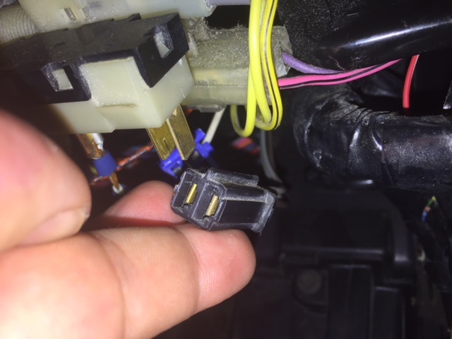
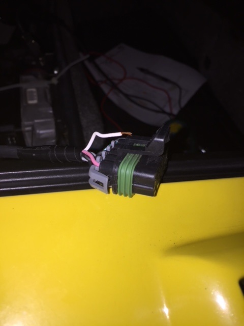
Pin G (White) w/No Brake: 0.L=0 Pin G also failed a test light test. I was puzzled by this. I investigated further. I gently tugged on the white wire at the harness plug connector and once again this was the result:
This is now the second wire that has broke free of its terminal on it's own, with no user error. This is a shame, considering the extremely expensive cost paid for my harness.
I have not re-pinned Pin G (White wire) yet but it does pass a test light test on the exposed wire itself. I am certain that this was at least part of the culprit, if not the entire cause of the cruise control not working.
Continuing on...
darbysan had mentioned that I need to be sure that the Cruise Inhibit signal wire Pin H (which in my case is Black and not DK Green) is also attached to Ground at all times. I tested it for continuity to ground and got a beep from the multimeter. The resistance test was as follows:
Pin H Resistance: Black wire (Not Green) 001.5 – 002.5 ohms. The reading bounced around no matter the grounding point used.
I have therefore concluded that my Inhibit is "grounded" rather than "open".
darbysan had also shared "that some modules need to see the Cruise Inhibit wire to ground, while others preferred it to be left open. If it goes to ground, then pulling the pin and leaving it out would be a good test. If it's not going to ground, then try grounding that wire and see if it helps."
"I don't know how your harness was built, but it will be either "grounded" or "open". Whichever way, you would want to try the other possibility as a test."
I plan to do this test if re-pinning Pin G (White wire) does not solve the problem with the cruise control working properly.
Additional testing of Pin F for continuity to ground yielded a beep on the multimeter. The resistance test was as follows:
Resistance Pin F: 017.5 – 018.1 ohms.
Many thanks to both Paul and Mike! Without your expertise, guidance and patience, I could not have gotten this far in my testing and diagnosis. I really appreciate this help and it is people like you guys that make this forum the special place that it is!
-Van
[This message has been edited by VanGTP5000 (edited 03-21-2018).]
After re-pinning Pin G (White wire) I was successful in pulling yet another wire out of the harness plug with virtual ease . This time it was Pin A (Gray wire). I went back and I now have all of the wires secured to their terminals in the plug but the cruise control still does not function.
I had initially planned to employ darbysan's test of pulling the Cruise Inhibit signal wire Pin H from the plug as a test to see if leaving it "open" would solve my problem. However, after struggling with three of the wires pulling out of their crimped terminals, I am very hesitant to attempt removal of Pin H from the plug. Especially given it's location right in the middle of the harness plug. Attempting to pull this Pin would almost certainly cause other wires to become dislodged again. I am sure a more skilled individual could accomplish this task better than my clumsy ass.
Having said that, I am thinking about just purchasing yet another digital cruise servo instead. With the thinking that the 96-99 Cadillac Northstar units Ryan mentioned earlier in this thread may solve the problem. After all fieroguru did mention 3rd unit is the charm . Apparently, Ryan has found much more success with these units (whether "open" or "grounded" Inhibit signal wires) vs. other similar servo units used in this application.
What do you guys think? I would also appreciate any interpretation of the resistance numbers I posted earlier. Are they even in the ballpark?


 . This time it was Pin A (Gray wire). I went back and I now have all of the wires secured to their terminals in the plug but the cruise control still does not function.


