Ok I'm stumped and not sure what else to do. I have been trying to hook an electronic cruise control on my 3800SC car. The module has a sticker that says V6 on it. Have to check my notes but think it came from a Bonneville. I have read through every test on this page: https://www.fiero.nl/forum/Forum2/HTML/090358.html and everything looks good. I do have the relay wired in. I have tried it with the inhibit switch grounded and floating. I have jacked the car up and spun the tires and verified that there is a low AC signal coming to the cruise so the VSS input should be good. The VSS is tapped from the ECM before the 'booster circuit' for the speedometer. Just pretty much stumped.
I think I either have a bad module or I am overlooking something. I want to mount the thing up in the furthest left corner of the engine compartment and the V6 one is perfect for that as it has the correct end for the 3800 bracket and the length is just right but if there is another known one that will go in that area or mount on the trunk wall in the original spot I'm certainly willing to change it out. Any assistance would be greatly appreciated.
** edited to correct for my complete inability to type
[This message has been edited by AlanD (edited 10-11-2010).]
Please post exactly where you have each wire connected. Although I'm using the 7730 ecm, I also wired a digital cruise in and it works perfectly. Maybe if you post how you wired it we may be able to help.
IP: Logged
11:20 PM
Oct 12th, 2010
MOBILE Member
Posts: 768 From: Linwood, MN, USA Registered: May 2002
I have this exact same problem, and I have already switched out the module... I was thinking of disconnecting the speedo adapter all together for a run, but haven't had time. I've also connected and disconnected the inhibit wires, checked the status with a scanner, etc, with no luck. Triple checked the wiring, and followed the GM troubleshooting charts in the factory manuals. I'm at a loss...
HELP!
------------------
Intercooled SC3800 II/III mated to a Getrag. 19's with 13" Brakes on all 4 corners. 5 years Avionics & 15 years Car Electronics.
Hmmm it is whatever drives the normal Fiero speedometer as the same signal is boosted and sent to the speedometer and works a treat. I'll make up a schematic today and post it so you can see exactly what I did. Where did you mount the cruise and what code did you use?
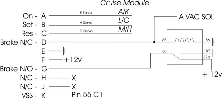
Here is the schematic. I have tried the inhibit both grounded and N/C but schematic shows N/C. Grounds are all hooked to the B wire of the Vac Solenoid. +12V are hooked to the fuel pump relay circuit. The jumpers are shown at the cruise module on the first three lines.
Both you guys are running the 3800 ECM? What is the PPM output of the ECM? I used the 4000 PPM output of the 7730.
Sorry for the slight highjack, but I have the same issue. Cruise is dead, tried multiple modules. Mine is a 3800 pcm from a 2000 GTP, and I'm using the 4000PPM output of the PCM. With the speedo conversion circuit I made from Darth's diagrams, the speedo works great. The cruise is tapped in below all that, just like his drawings.
[This message has been edited by PURPLE REIGN (edited 10-14-2010).]
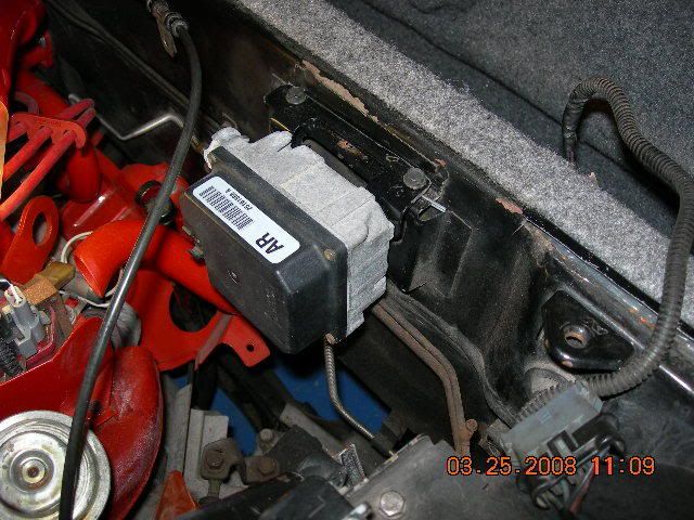
I used the AR version and mounted it like this. (not my car in the pic) I did not originally have cruise so I scavenged a cruise stalk from the junkyard. I grabbed the whole wire from the cruise stalk including the female connector with pigtails that the male cruise stalk wire connects to under the dash from the donor car.
I do not know how to read your wiring diagram above. I can tell you that I did not use any relays in mine. When researching this I learned that Pin D and Pin G need to be wired into the brake lighting so that the cruise module sees the change in voltage when you step on the brakes.
Also, I don't have the exact color codes for the cruise stalk wires with me here in Chicago. I can get them when I get home Sunday though if you need them. I do believe the wire colors are the same across different GM cars.
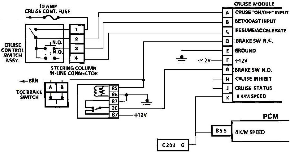
Pinouts: Pin A - Cruise ON/Cruise Off Pin B - Set/Coast Pin C - Resume/Accel Pin D - TCC Brake Input Normally Closed (Hot all the time) Pin E - Ground Pin F - Ignition B+ 12v Pin G - Brake Lamp Input Normally Open (Hot only when braking) Pin H - Cruise Inhibit Signal (AR needs this grounded, others may need it open) Pin J - Cruise Engaged (goes to ground when engaged. Used to light the IP light) Pin K - 4k ppm VSS Input Signal (from BB11 on the 7730)
[This message has been edited by Hudini (edited 10-14-2010).]
Well I went to the PickNPull yesterday and got an AR marked cruise. I'll put it on today and see what I can get going. Looks like the only change I'll have to make is grounding pin H. I'll be sure to give an update today.
Ok well I changed the cable over to the shorter one I was using so I could mount the module in the drivers front side of the engine bay. I then hook up the connector, grounded H as apparently the AR module requires it and zip tied the module in place for a test. Went for a quick spin. Engaged it at 40 and it worked like a champ. Either I had a bad module or the V6 stamped modules are very picky about what they are given for signals. Either way the AR module works fine with the schematic I posted plus grounding the inhibit line. Thanks everyone.
IP: Logged
07:54 AM
PFF
System Bot
Oct 23rd, 2010
tampalinc Member
Posts: 776 From: Waukesha, WI Registered: May 2001
Does anyone have pictures of how they wired up D and G under the dash? I have tried a couple of different ways and none have worked. I wanted to make sure I have it hooked up correctly before I go and purchase another cruise module Monday morning. I am trying to get my cruise working before I leave for Illinois Wednesday morning. The trip is 670 miles each way.
IP: Logged
08:09 PM
May 26th, 2011
americasfuture2k Member
Posts: 7131 From: Edmond, Oklahoma Registered: Jan 2006
I wanted to let everyone know that I've run into this same issue as well with SOME cruise modules. I have about 5 modules on the shelf that REFUSE to work in a Fiero. But if I plug them in to my 1996 Olds 88 3800, they work just fine. I speculate the problem might be that some of these modules (the ones that don't work in the Fiero swaps) may look for the cruise inhibit circuit to change state while driving (since this is a PCM-controlled output), and if they don't see that, they won't work. So if you have a module that refuses to work in your swap, you may try hooking the cruise inhibit and cruise (engaged) status wires up to the PCM. NOTE: this will probably only work if you have the 4T65-E transmission in your swap. Some PCM's disable cruise operation (via the cruise inhibit circuit) unless the shifter is in overdrive.
I am going to test this theory on the next swap I do to see if I can figure out if that is the exact problem or not.
-ryan
------------------ OVERKILL IS UNDERRATED Custom GM OBD1 & OBD2 Tuning | Engine Conversions & more | www.gmtuners.com
[This message has been edited by Darth Fiero (edited 05-26-2011).]
IP: Logged
01:49 PM
ILVMYGT Member
Posts: 405 From: Port Orchard, Washington Registered: Jun 2003
I am trying to get my cruise working before my trip this weekend. I have tried two different cruise modules and can't get them to work. Can someone tell me if they see a mistake in my wiring. This is wired into a car that didn't have cruise.
Cruise Module Pin A > Cruise ON/Cruise Off > Cruise Switch, Grey Pin B > Set/Coast > Cruise Switch, Blue Pin C > Resume/Accel > Cruise Switch, Grey/Black Pin D > TCC Brake Input Normally Closed (Hot all the time) > 12v Ign Pin E > Ground > Ground Pin F > Ignition B+ 12v > 12v Ign Pin G > Brake Lamp Input Normally Open (Hot only when braking) > Blue wire on brake switch (12v only when brake applied) Pin H > Cruise Inhibit Signal (AR needs this grounded, others may need it open) > C1-72, also tried grounding it Pin J > Cruise Engaged (goes to ground when engaged. Used to light the IP light) > C2-59 Pin K > 4k ppm VSS Input Signal > C1-55
Cruise Switch Grey > On/Off > Cruise Module, A Blue > Set > Cruise Module, B Grey/Black > Resume/Accell > Cruise Module, C Yellow > 12v Ign > 12v Ign
[This message has been edited by tampalinc (edited 06-27-2011).]
One thing that may be the problem is when you press the brakes, pin D & G must change state. G goes from ground to 12V and D goes from 12V to ground. That is what I installed the relay in my setup for. I have to check my notes but the A on the cruise vac sol, wires you may or may not have with the cruise not already installed - sorry no non-cruise car to look at, should be providing the 12V when the brake is not pressed.
The A Vac Sol line provides 12V to the relay and on pin D. The relay is closed and pin 87 connects through to pin G providing the ground. When the brake is pressed 12V goes away on the A Vac Sol line and the ground from the relay coil is seen at D. The relay opens at this time also and connects the +12V to pin G. This is the only way I could get it to work is to add a relay to show solid +12 and ground to those two pins which alternated when the brake was pressed. Also the module must see the state change once or twice before it will engage or that is what I have been told but haven't confirmed.
-edit- oops got some pins backwards. Should be right now
[This message has been edited by AlanD (edited 06-27-2011).]
IP: Logged
06:18 PM
tampalinc Member
Posts: 776 From: Waukesha, WI Registered: May 2001
What is the A Vac Sol line? This car never had cruise installed from the factory. Is the A Vac Sol line something that came on cars with factory cruise installed?
Yes it is pin A on the Cruise Vacuum solenoid. The line basically comes from the normally closed side of the brake switch. You would need to run a wire from 12V to the normally closed side of the brake switch then out to pin D. You may be able to get away without the relay. Mine seemed to be picky about the signals so I needed the relay.
That is the way mine is. The brake switch has 12V going through it at all times unless you press the brake. It sends 12V to both pin 85 and pin D. When the 12V is there the relay is closed and ground is seen at pin G.
When brake is depressed, the 12V goes away on pin 85/D and the ground through the relay coil is seen at pin D. The relay is open and has pin 30/87 connected putting the +12 to pin G.
I fought this fight for about two weeks and tried three modules. I finally got it working with the schematic I posted and an AR module.
I dropped you a PM with my phone number if you want to call and try and work through it.
IP: Logged
07:37 PM
tampalinc Member
Posts: 776 From: Waukesha, WI Registered: May 2001
Major thanks to AlanD. He walked through his setup with me and helped me determine I wasn't getting power to the correct brake switch. I ran power to the brake switch, ground Pin H (AR module), and my cruise is working now.