Longer flywheel bolts arrived this week, but I haven't switched them out yet.
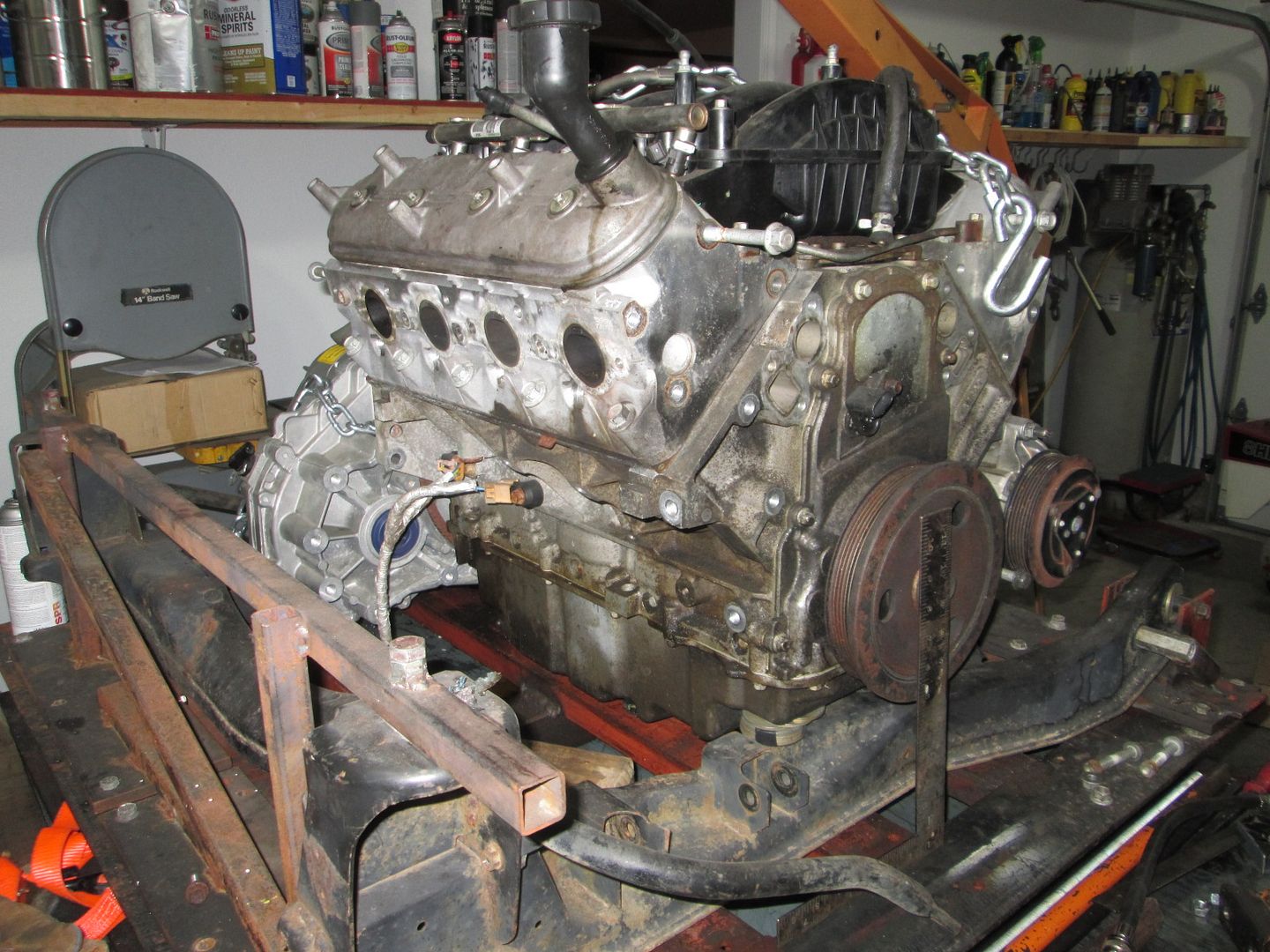
With the flywheel installed, I went ahead and did a compression check on all cylinders. Cylinder 6 is low @ 115 vs. the 180 average of the other 7. This is a DoD cylinder, so the likely suspects are carbon build up in the rings or a collapsed lifter. I probably should get my engine stand out of storage so I can tear into this engine and see what its issue is.
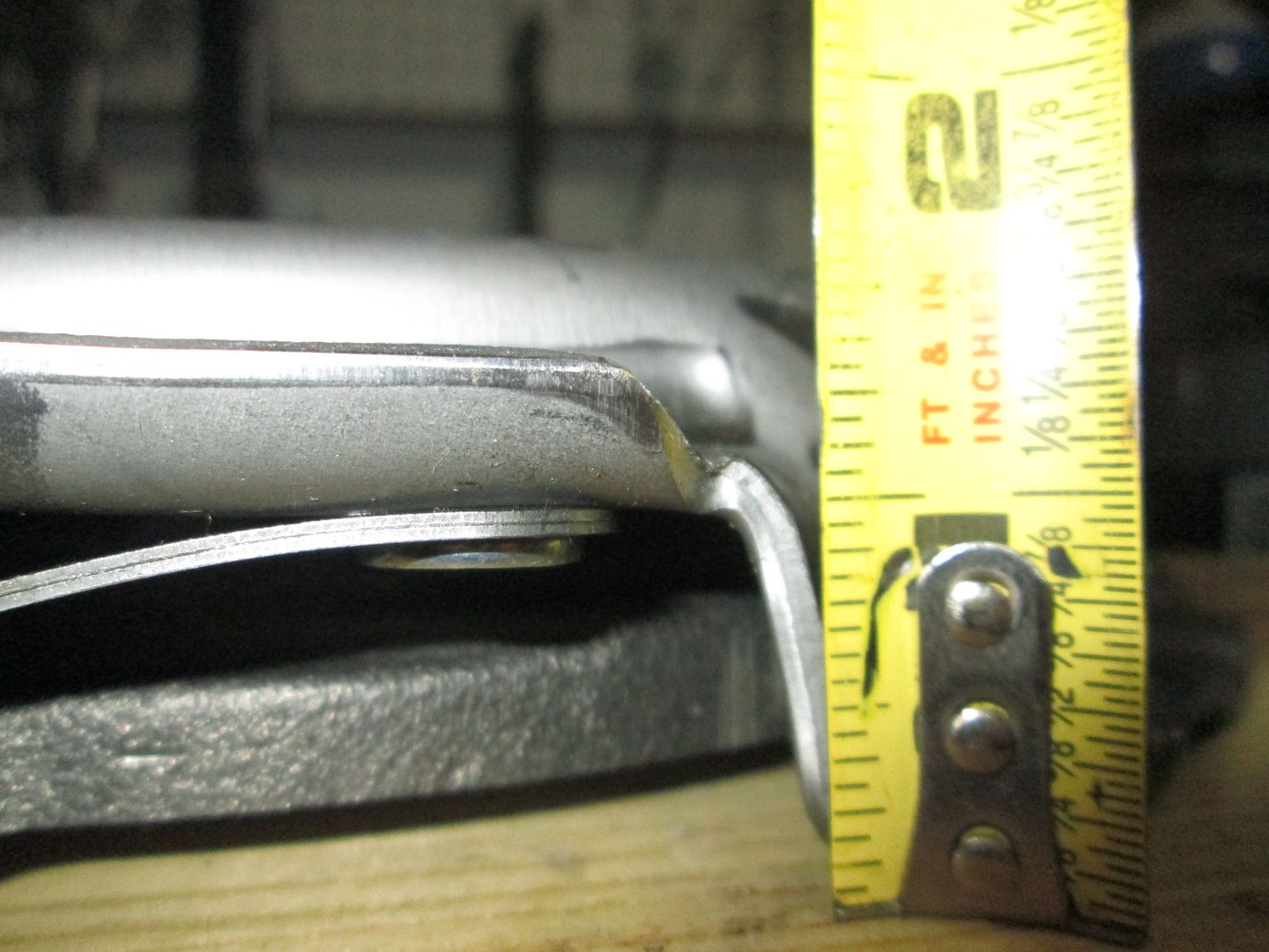
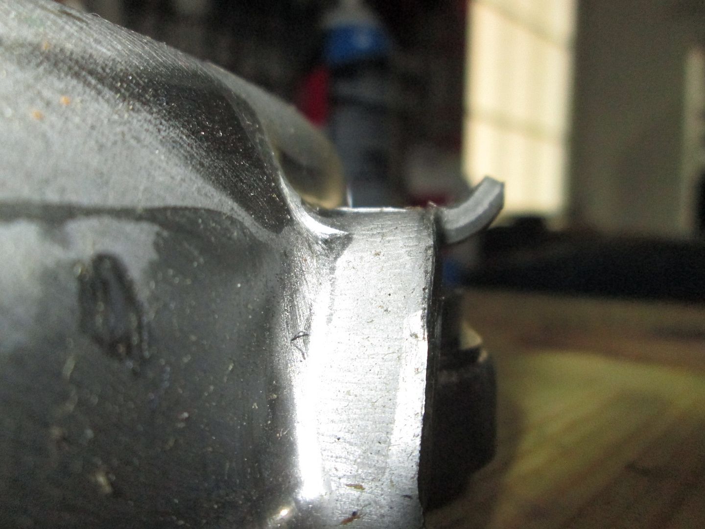
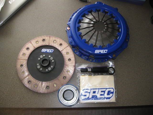
Put the cheapo clutch/pressure plate on and continued the process of verifying dimensions and clearances. I did find one issue unique to this pressure plate and not present on the stock Ford or Spec units. This raised shelf at about 1 1/4" is normal, but the turned up lip at the outer edge isn't and it hits the differential buldge.
When I installed everything and noticed it was hitting, I bumped it from both directions to get an idea of the interference. Its not much, maybe 1/16", but it is an issue and people will need to know to look out for it when buying pressure plates.
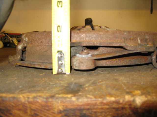
Here is the original one that I pulled from a junk yard (notice the shelf is there, but the raised end isn't):
I don't have a real good pic of the Spec pressure plate, but in this one you can see the raised shelf was cut at an angle on it and it doesn't have the raised lip.
[This message has been edited by fieroguru (edited 07-02-2016).]
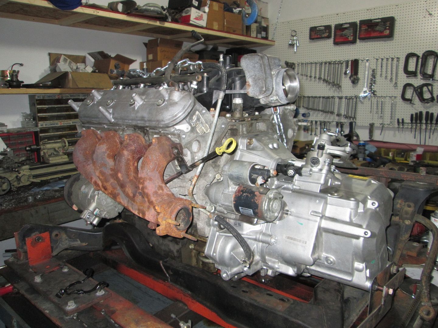
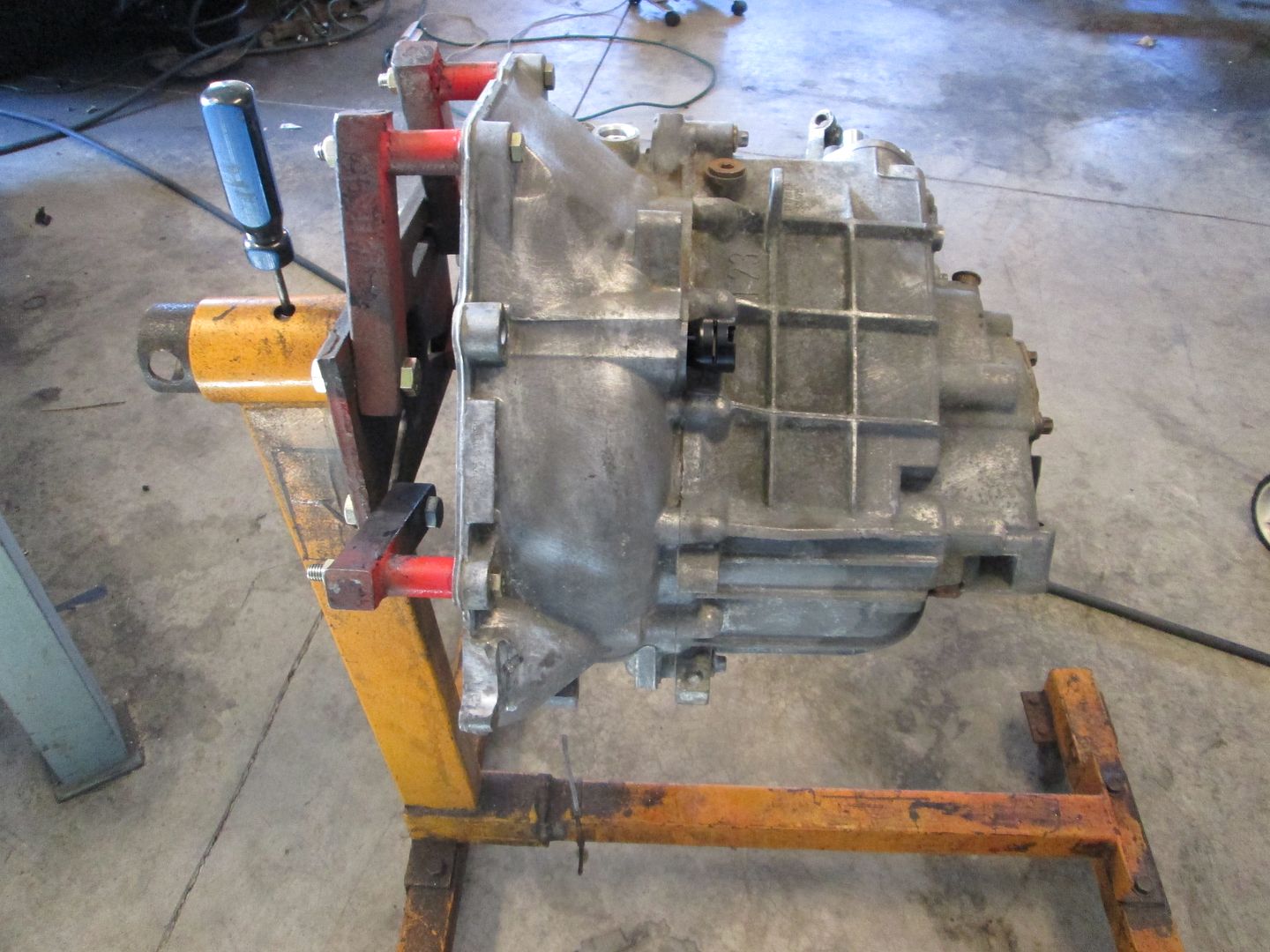
I went ahead and swapped the locations of the LS4/4T65E-HD and the LS4/F40 so it was on the cradle on the bench. Then I pulled my Fiero into the garage, removed the rear wheels and then took the needed measurements to match the position to the LS4/F40 on the bench.
When I did the first swap, the first thing I did was remove the front and rear crossmembers and install 2x3 ones that were relocated. With this swap, I would like to have as few cradle/chassis mods as possible. Welding of the mounts to the cradle will be required, but I want to limit the end user fab work.
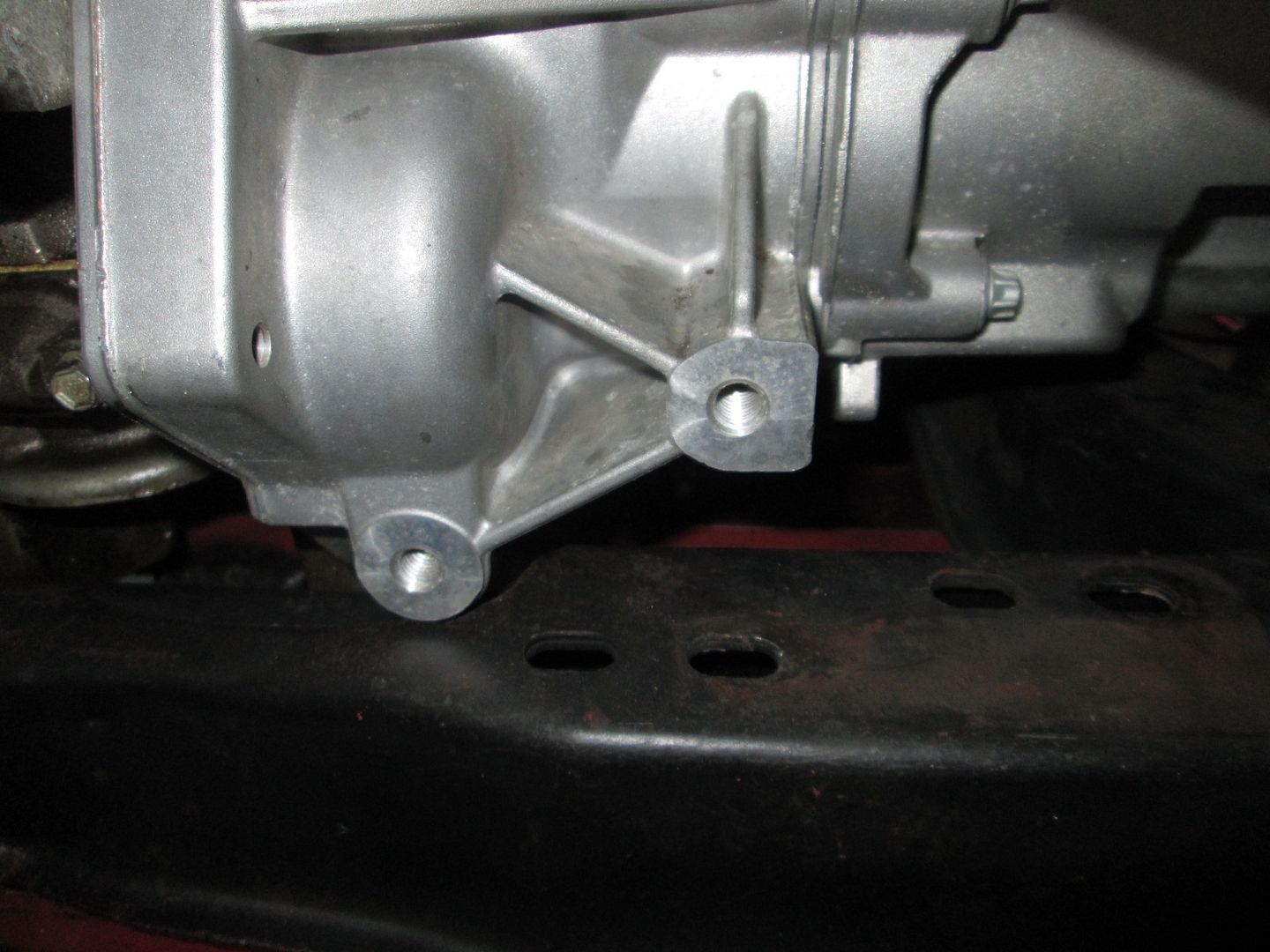
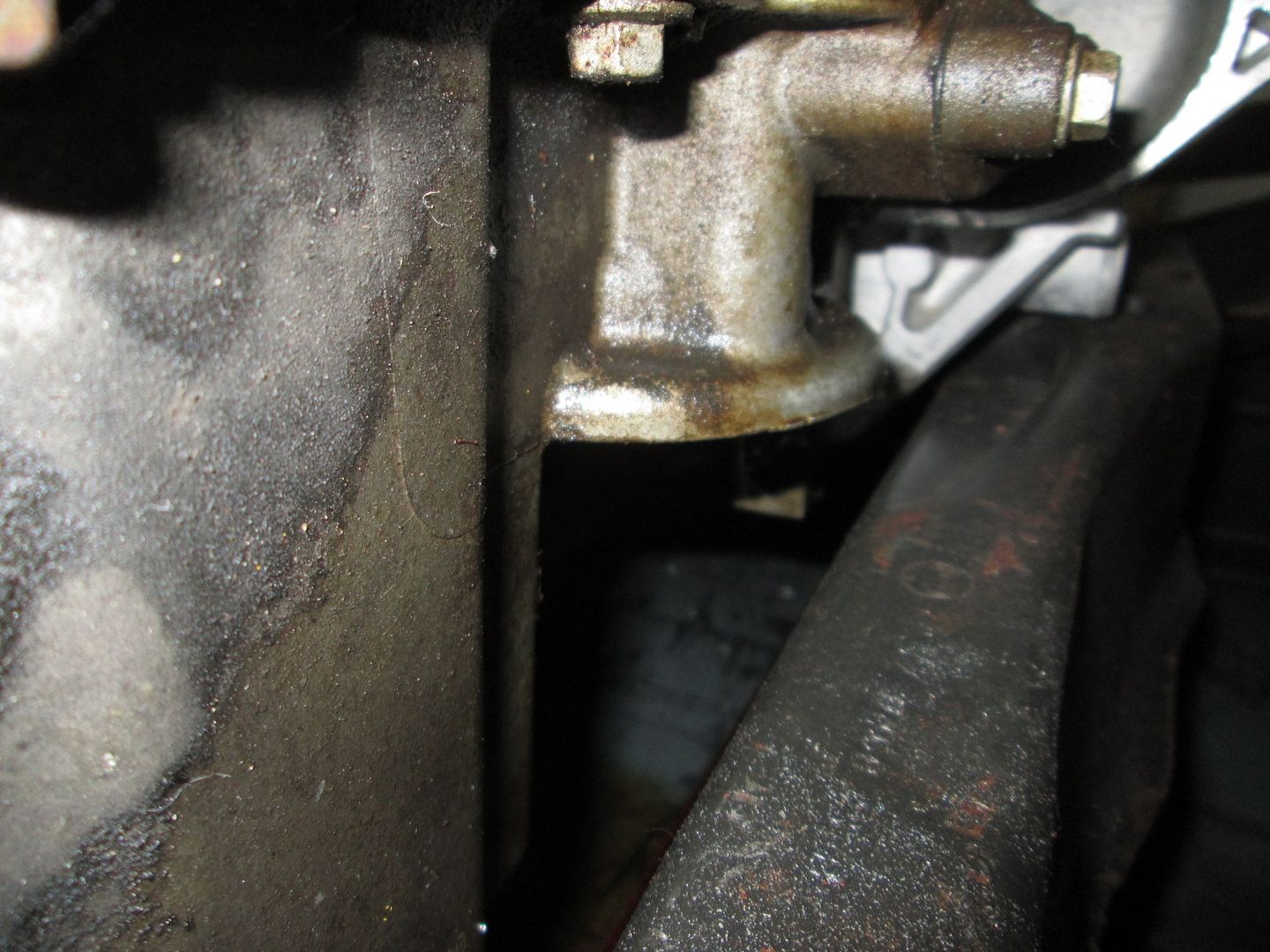
Here is one of the primary areas of concern. If I keep the same elevation as my original swap, this bolt boss would need to be slightly below the crossmember surface. If I raise the engine placement about 1/4" it will clear w/o any need for modification.
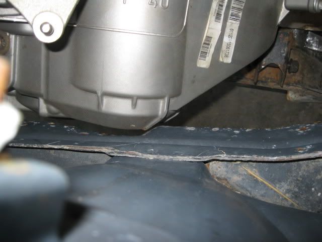
Another area of concern is the oil filter. From the top it looks like the oil filter will clear the crossmember, but there is a bottom flange that will likely get in the way. Moving the engine/transmission to the rear would help clear this area.
The third area is transmission to the DS frame rail. Here is an old mockup from my original install before I relocated the factory notch in the frame. As you can see moving the engine/transmission to the rear makes this clearance worse. However, the balancer on my original swap clears the DS frame rail by 3/4", so I could shift everything to the passenger side by 1/2" to get more clearance in this area. For my original swap, I relocated the factory notch so there was uniform spacing around the transmission... I doubt anyone else would do through the trouble...
Here is after the notch was moved:
So with some slight shifting of the drivetrain placement vs. my original swap there shouldn't be very many areas where the 88 cradle will need to be cut/clearanced. I think the oil pan will still hit one of the uprights on the stock engine mount pad, but I will have to pull another 88 cradle out of storage to verify as this one already has had it removed.
As seen above, I also relocated the dipstick... but I did it similar to my original install, so I think it will hit the stock LS4 crossover...
I also swapped sides with the valve covers so the oil fill will be on the back side. While doing this I noticed that with the coil bosses still on the valve covers, I can't remove the extended oil fill and just install the cap in the valve cover like my original swap... the cap hits the boss.
[This message has been edited by fieroguru (edited 07-03-2016).]
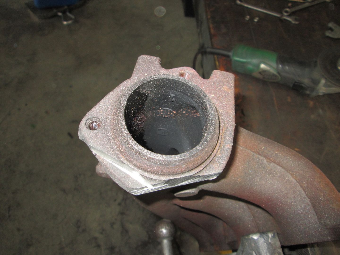
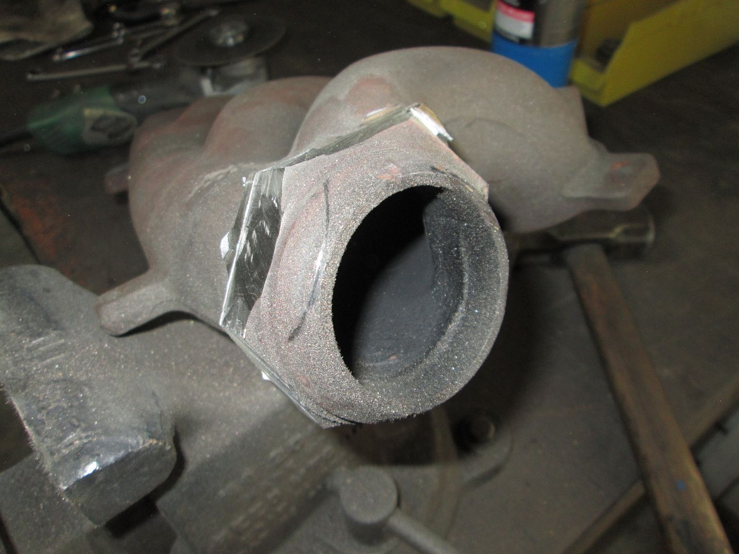
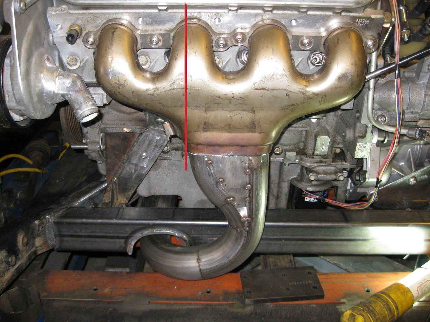
This week I took a little detour and played with some exhaust manifolds. The front one flows pretty good, but I wanted to convert it to a v-band setup vs. the factory 3 bolt. So I with a little cut off disk action and A LOT of grinder work I got it ready for the v-band:
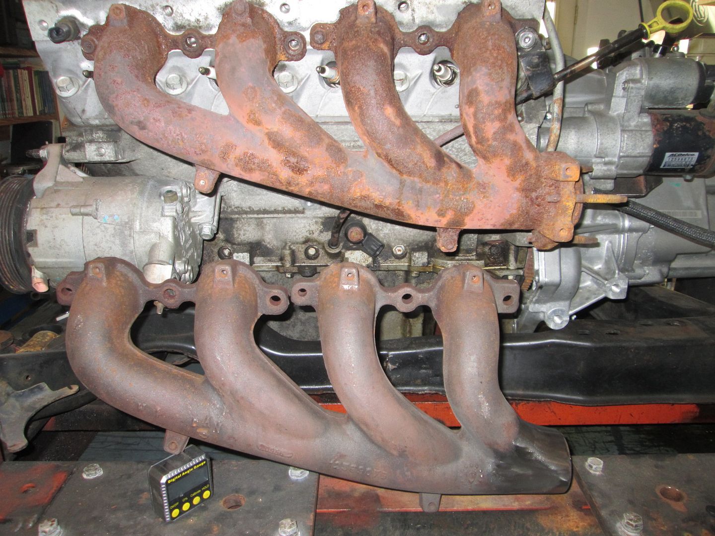
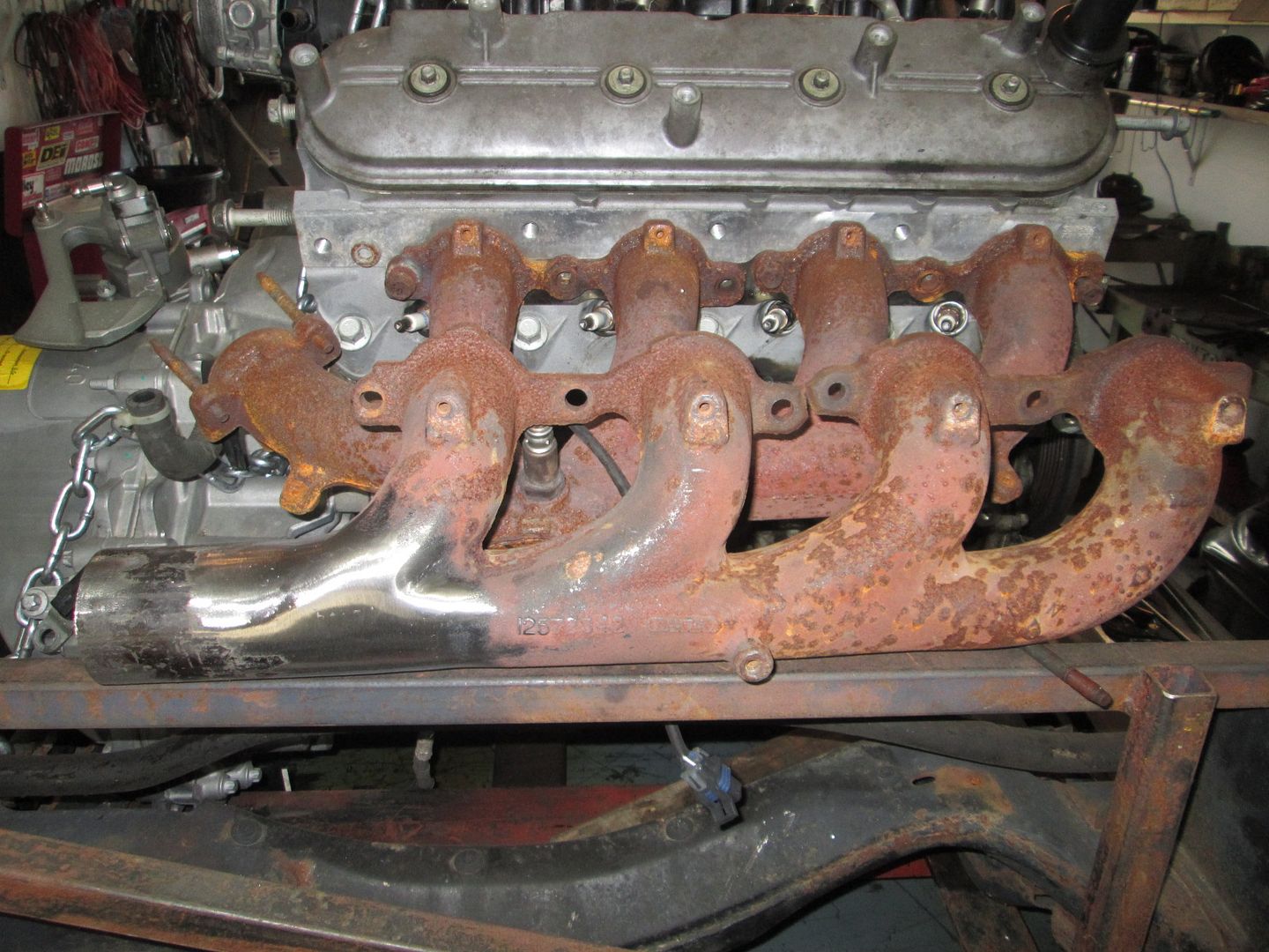
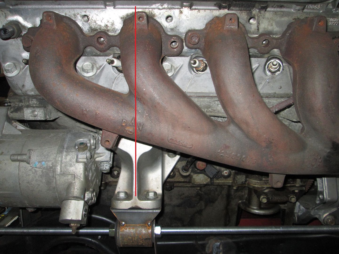
Now, if you wanted to run the exhaust in the original fiero route, you need a rear manifold that dumps to the rear (similar to the front LS4 manifold). A passenger side truck manifold is close, but it still needs some significant work to make it fit better. This is not my picture...
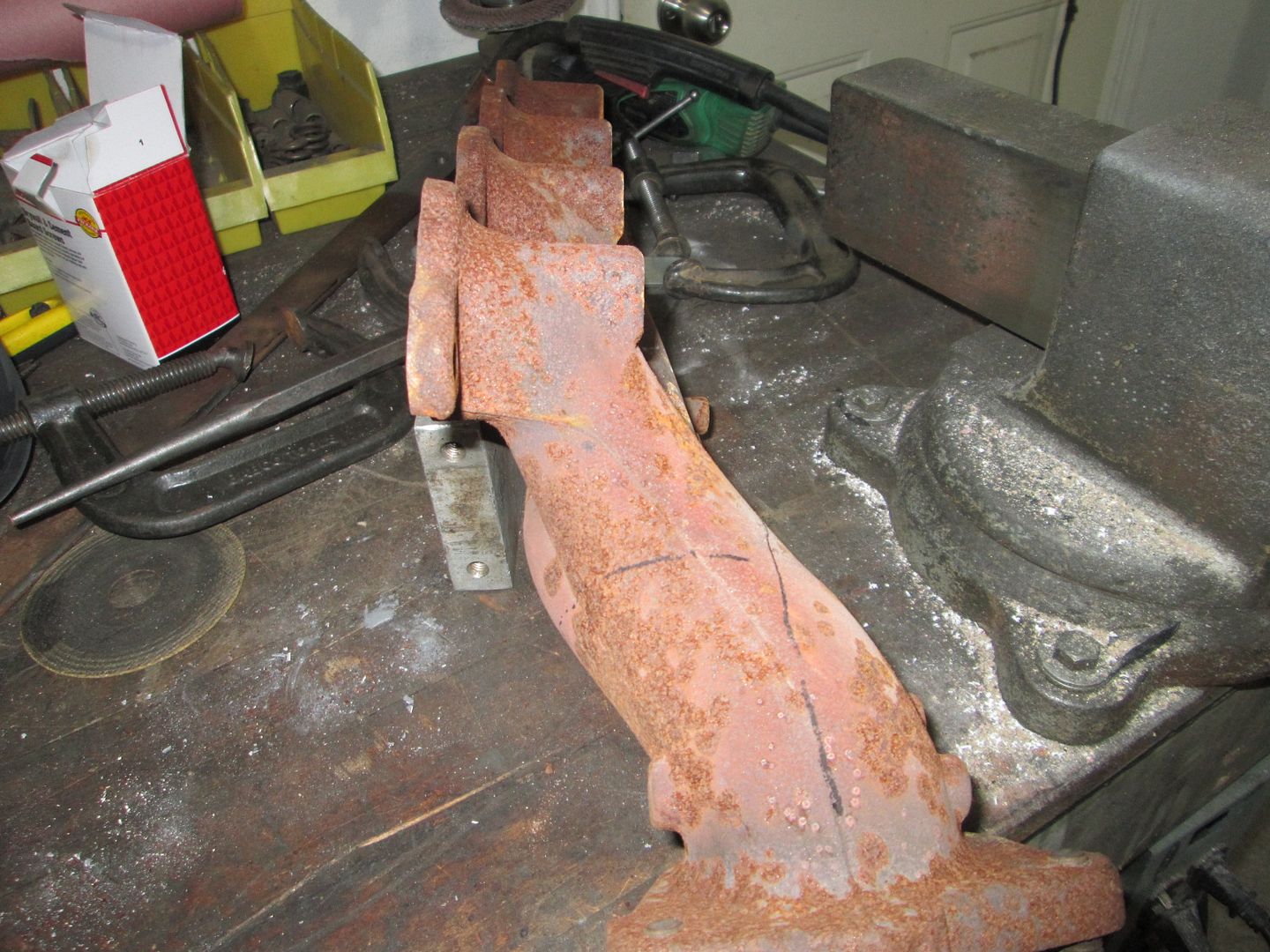
Here is one of my pics showing an end view with some rough marks in the areas to cut:
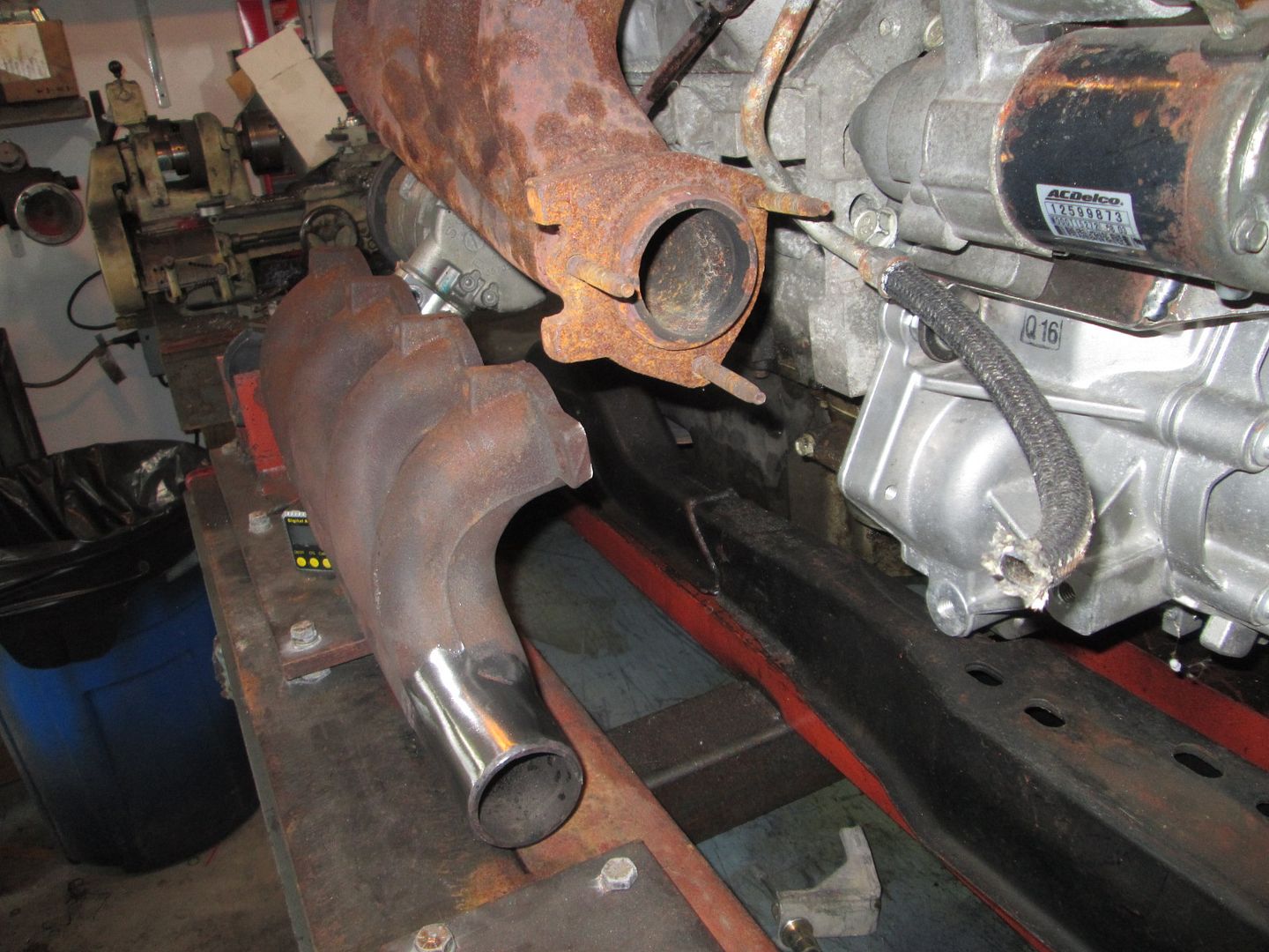
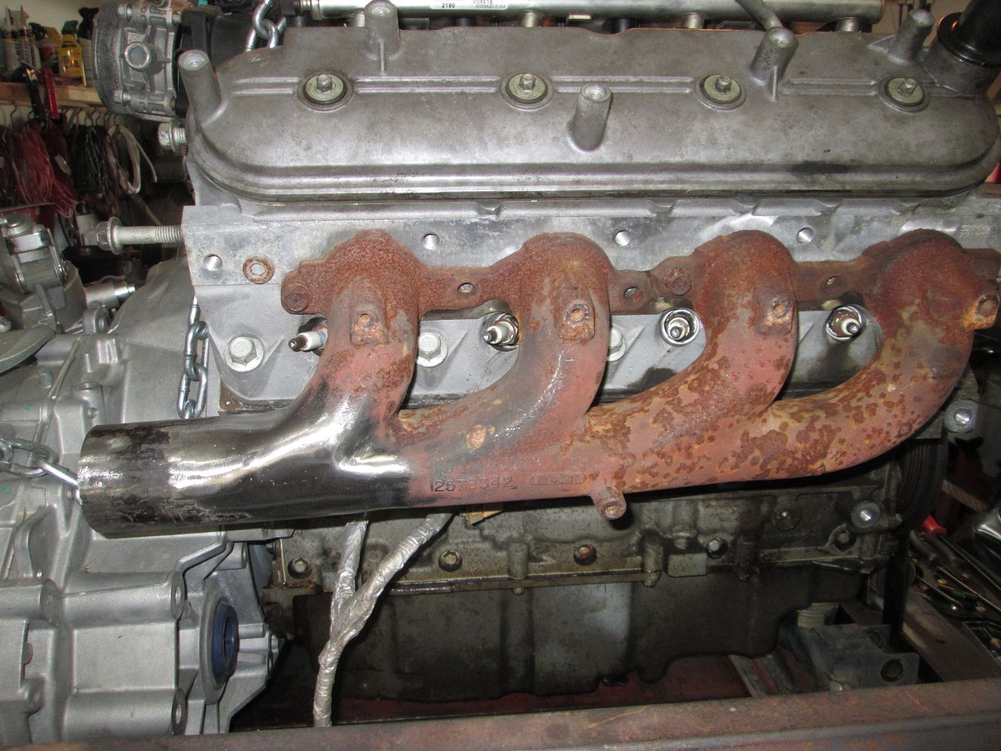
After some welding and grinding I ended with this. The added section of schedule 40 pipe is too long and will be trimmed back.
Now both exhaust manifolds dump to the rear so you can route the exhaust like a stock Fiero, or for some other purpose... The v-bands should be here in a few days along with the O2 sensor bungs.
[This message has been edited by fieroguru (edited 07-07-2016).]
Guru just curious why you want to use V-band clamps on your exhaust?
I've had headers on two different vehicles that both used V-band clamps and I hated them. Both systems had leaks at the joints that were mated with V-bands, and nothing I tried could solve the leaks (and incessant ticking noise). After the second experience I swore that I would never buy another exhaust system that used V-band clamps anywhere. The OE style that you have cut off of your manifolds would seal up much better and much easier. I see the major flaw of V-band joints in that you are attempting to seal two flat surfaces together without a gasket, and apparently not enough clamp load from the V-bands. V-band joints would probably work 100% better if there were some overlap between the two pipes being joined.
All kidding aside, I had a set of FOCOA headers that came with V-band clamps. Once I got the "too short" Y-pipe sorted out (had to add a half-inch section to one side of the Y) they sealed perfectly.
Originally posted by Raydar: "This one time, at band clamp..."
That was funny!
Now shifting back to actual work for this swap...
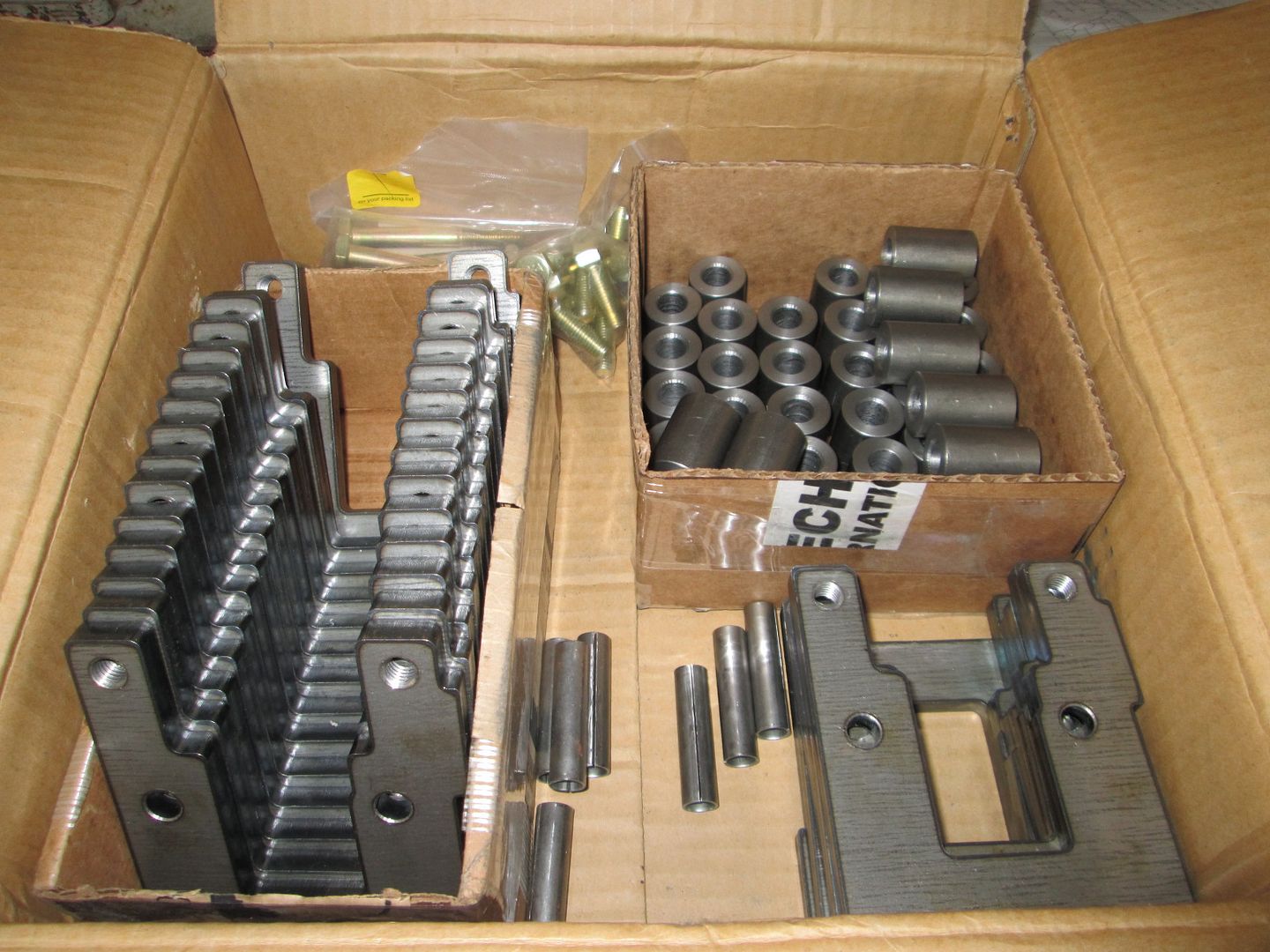
With the new placement of the engine/transmission finalized, I started work on the front mounts. Right now most of the brackets are merely templates made from 16ga to fine tune the bracket design. Eventually I will remake them in 1/8" steel, but for now you can get a general idea about what the mounts will look like.
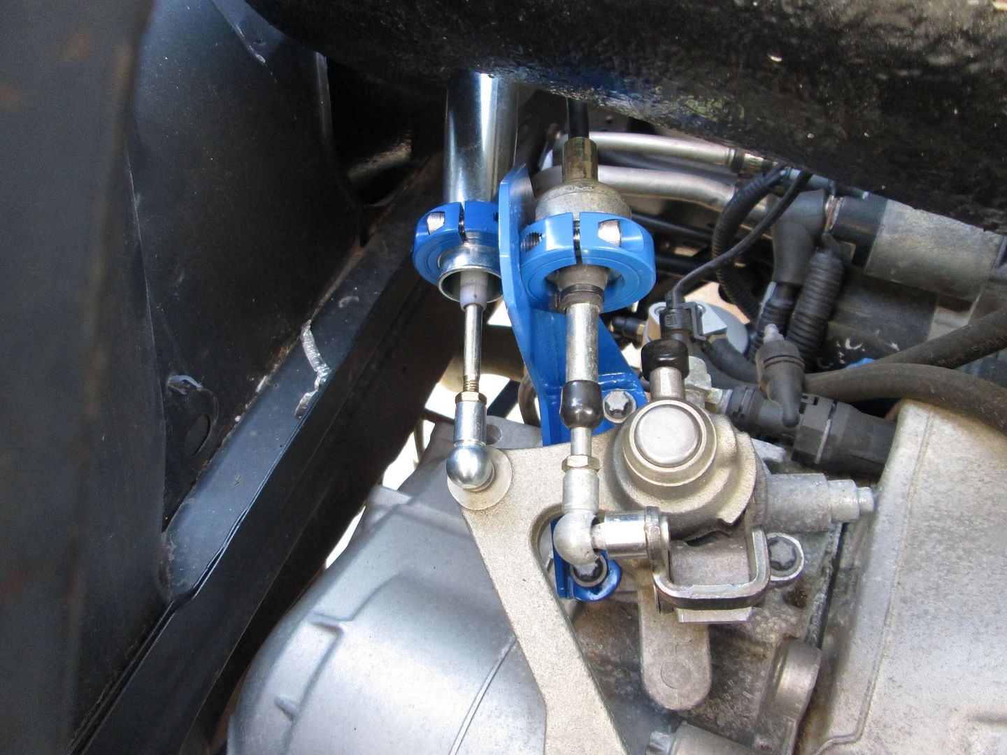
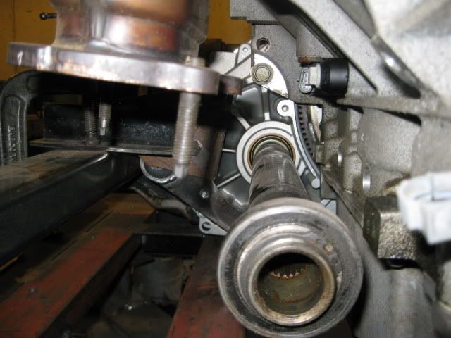
Front Engine Mount - The top section I made 2+ years ago for the LS4/4T65E-HD swap and it attaches to the stock LS4 engine mount bracket. The two bottom ears are pretty simple and fit along the front and top of the crossmember. They will be welded to the cradle.
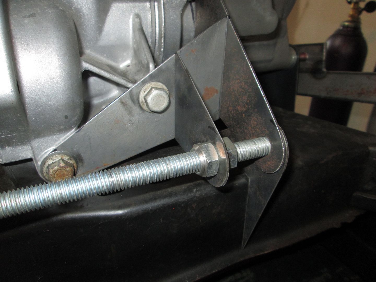
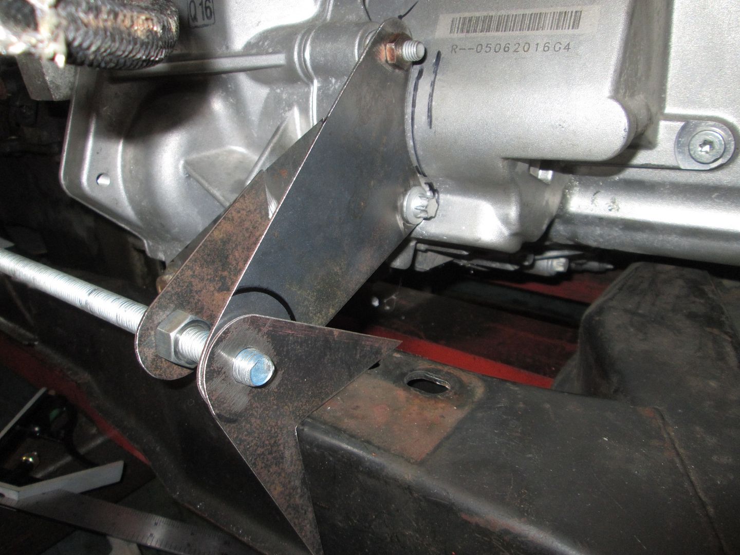
Front Transmission Mount - There are three pieces that come off the transmission. Not shown in the picture, but the transmission side brackets still need to be cut to accept the bushing sleeve (you can see the sharpie mark to make this cut in the 3rd picture). Like the front engine mount, there will be simple ears that will be welded to the cradle on the front and top side.
I will likely finish the templates for the front mounts, then move to templating the rear mounts. Then I can do all the 1/8" metal cutting at the same time. However, this upcoming week and weekend will be busy, so I probably won't have much garage time.
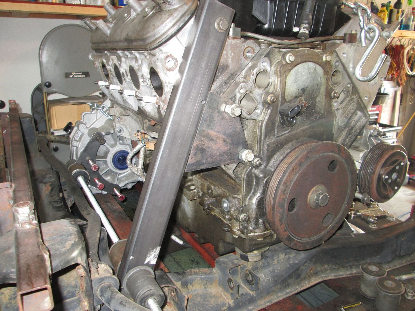
I worked on the rear mount templates a little this weekend. Just like the front, the rear mounts are co-linear and parallel to the front mounts, but their elevation is slightly different.
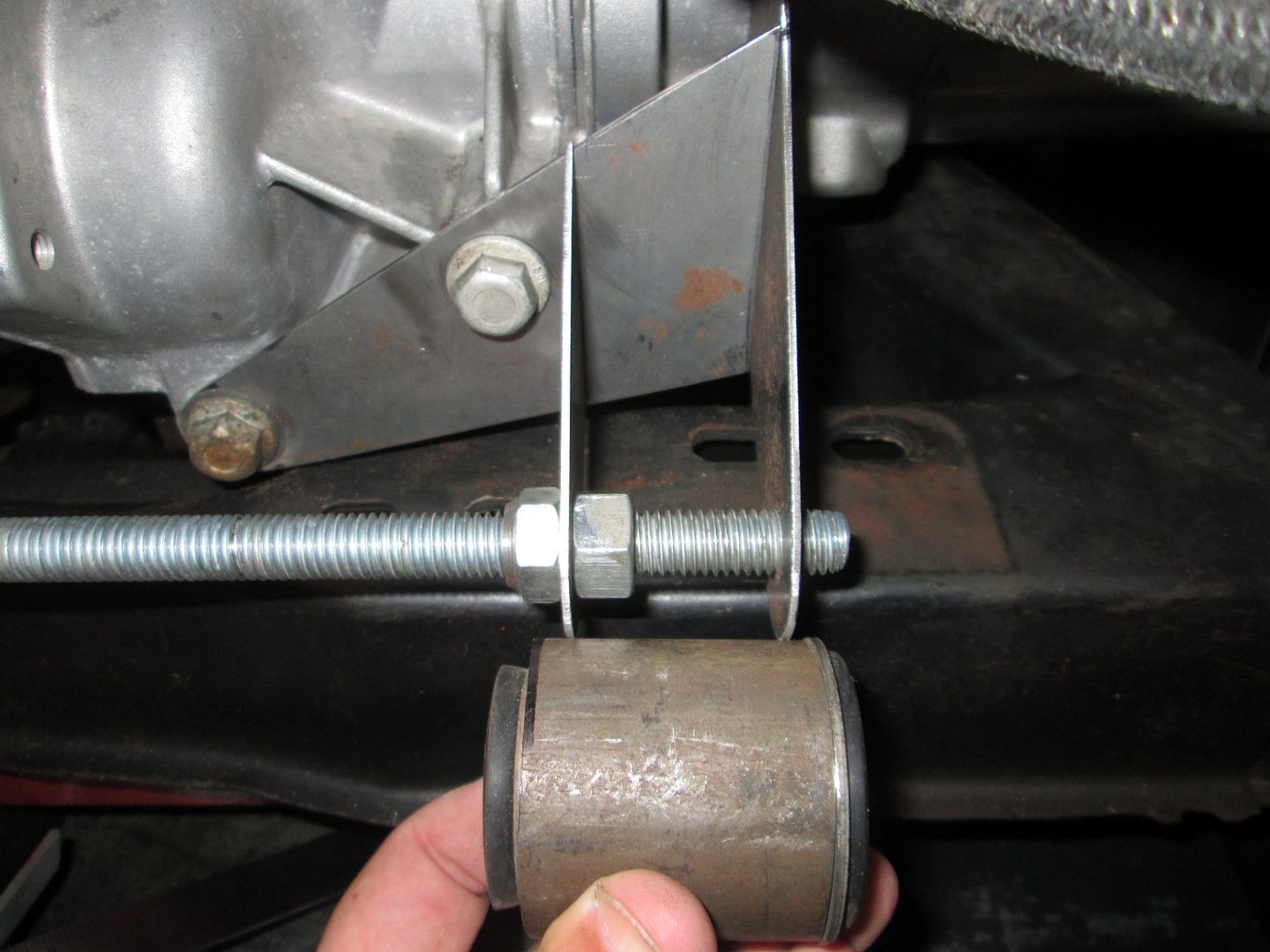
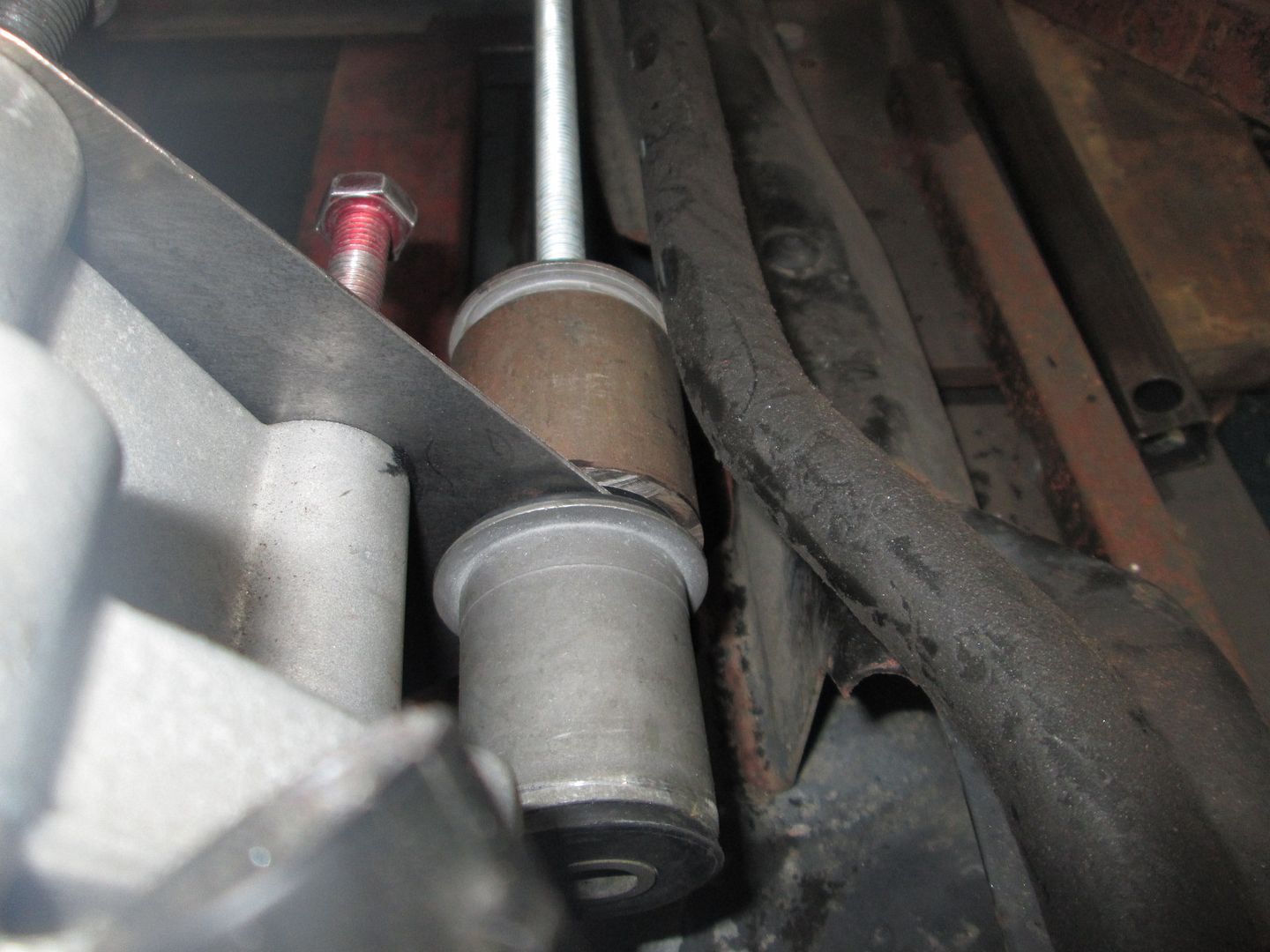
Here is the rear transmission bracket. Ignore the two bushings, only one will be used and it will be centered in the mount. Those are just there to ensure the mount clears the differential housing as well as the sway bar in the full droop position. I haven't started working on the tabs that will weld to the cradle yet.
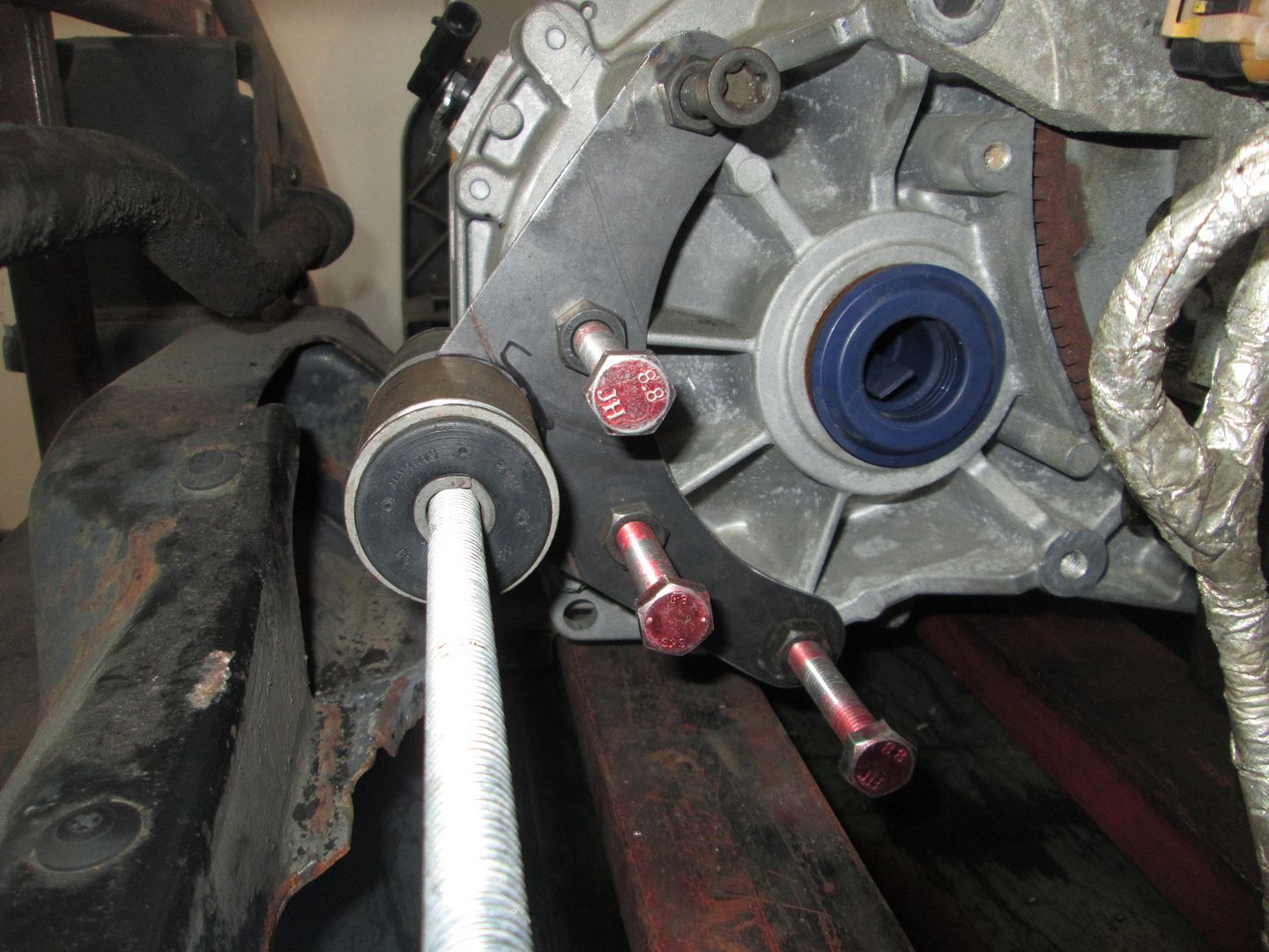
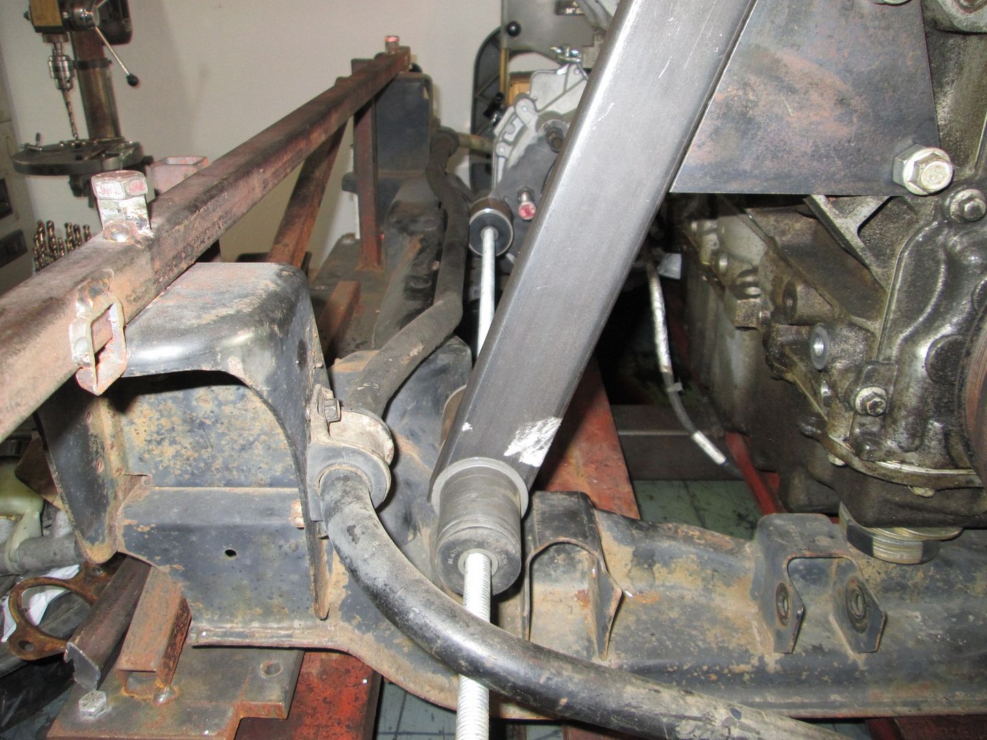
Here is the rear engine mount. The tube will be cut to accept the bushing and then there will be a couple of tabs to the cradle as well.
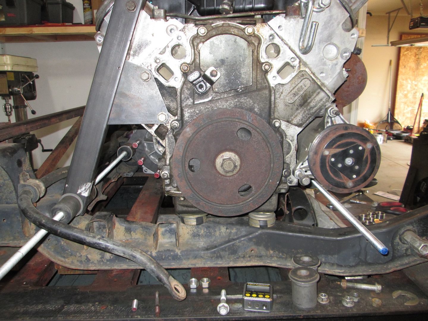
Here you can see the ends of the all thread that passes through all the mounts. They are over 21" apart, which will significantly reduce the load from drivetrain torque.
All the parts for 5 LS4/F40 starter brackets should be done at the laser cutter this week and 5 LS4/F40 flywheels have been ordered, but will take several weeks before the flywheels are done. So for those of you waiting on the LS4/F40 flywheel and starter bracket... we are getting close!
Last weekend I was playing with the starter mount parts and making a fabrication fixture and had an epiphany... As I was fabricating the fixture and assembled the first bracket, I thought of a better way to mount the starter that would help make the bracket simpler and "more universal".
The original design with the tabs required either the tabs to be spaced from the bellhousing or just welded on one side. So the side with the least overlap between the tab and the mount base was welded both sides and used a spacer while the other longer tab was welded on only one side. As people have been PMing me about applications beyond the F40, I knew the rear stabilizing tab would only work with the F40 and every other transmission would need something different.
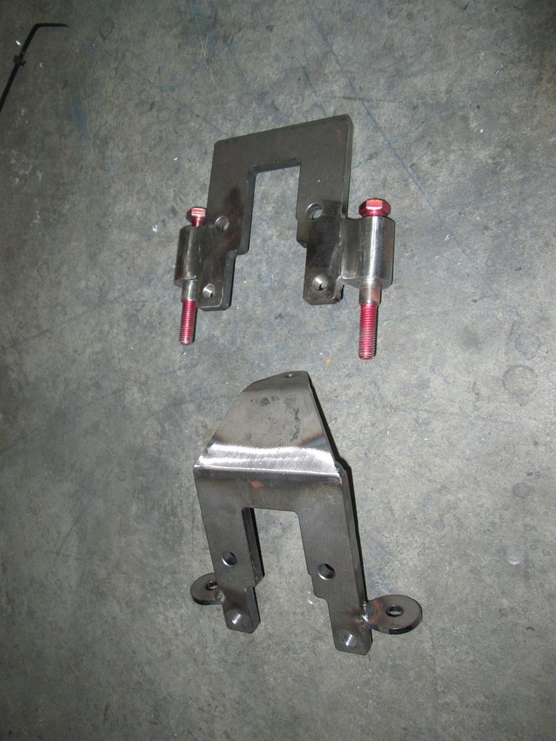
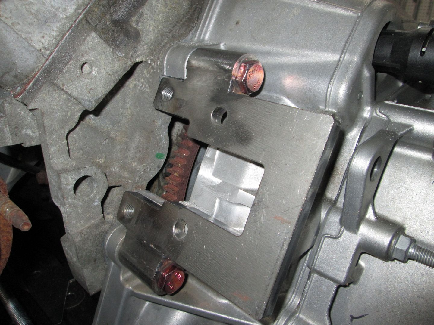
While messing around with the needed spacer on the first starter bracket, I thought about just using longer sections of thick wall tube that will run along side the base and could be welded top and bottom. Here is picture of both styles of the starter bracket. The one with the bolts is the new more universal style.
I say "more universal" instead of "universal" because this (and the previous design as well) attach to the bellhousing flange and I fully expect them to be slightly different thicknesses between the various transmissions. If I get time over the weekend I can run over to the storage unit and measure a Getrag and Isuzu for comparison.
So now 3 of the 4 parts I had made for each starter mount will not be used for this project at all and go in the scrap pile... all part of the R&D efforts.
So that 'tab' didn't bolt or connect to anything? I just assumed it was there for a third connection point. Is it safe to assume that two bolts are enough then? I suppose so, but just wondered.
The small tabs are only 3/16" thick and while they do a good job for maintaining the precise placement of the starter nose end of the bracket relative to the ring gear, they are too thin to properly stabilize the starter end of the bracket. Granted the load point that would cause deflection is the ring gear and that is very close to the small tabs. It is in front of the tabs which would provide a force to push the rear of the bracket closer to the transmission. In the initial mockup it was too easy to deflect the rear of the bracket by hand, so the large 3rd tab at the end was added.
When I made the original starter bracket 6 years ago, my primary goal was to simply get the starter mounted for my swap. I didn't care about making the bracket again or trying to make it work with other transmissions. As I now look to manufacture more brackets, the simplicity of design, speed of assembly, and potential application to other transmissions become new design criteria (as well as proper fit, function, and durability). The issue is the 3rd tab at the rear uses a bolt/stud that is only in that position on the F40. The Getrag and Isuzu have bolts in that general location, but they are not in the same position, so that part of the bracket would have to be different for those transmissions. Additionally, that bolt/stud for the rear tab doesn't even exist on the F23 as all the bolt heads are inside the bellhousing.
With the two large diameter shafts, the clamp load of the bolts, the extended weld connection between the bracket and the shafts, and the location of the load point that would cause any deflection (ring gear), there is sufficient strength to stabilize the bracket and starter in all directions. This new bracket is very strong/stiff and has been verified by using a jump box to crank the LS4/F40 over many times checking for any deflection or movement during engagement. This new design also becomes more adaptable by lessening the connection point variation.
[This message has been edited by fieroguru (edited 08-13-2016).]
That makes perfect sense, I hadn't thought about the fact that the longer sleeves for the bolts would stabilize the starter. Smaller and simpler designs are a good thing!
you just opened up your market alot with that design, not only transmissions, but engines too, as long as the right size ring gear is used, along with the same placement, this could be used on SBC(Non LS4) based swaps as well. or on any engine using a 60V6 bellhousing and wanting to move the starter.
As I wait for the starter mount and flywheel to become ready for sale, I wonder how this mounting system will work with the LS7 exhaust manifolds. Since I already have these and have made up my mind that they are must have for this build I wonder how they will work with the new front motor mount? Also would there be any issues using these with the stock cradle cross members? I have seen others having used them so think I should be OK. Any thoughts on the subject?
5 flywheels are currently being made... so the will be available shortly.
As for the LS7 manifolds... I believe they will clear the mounts for this setup, especially if you cut off the flange like I did. On my first swap, I moved the cross member about 2" further forward and the rubber bushing is between the oil pan and the cross member. So keeping the cross member in the stock location, there is plenty of room for the down pipe to pass by.
Here is a pic showing the edge of the body vs. the center of the exhaust port. Followed by the same pic showing the center of the mount body.
Then from an old pic you can get a general feel for how far the LS7 manifolds protrude from the block vs. the differential housing. This is also a good picture to show the outlet flange is about 2" above the oil pan.
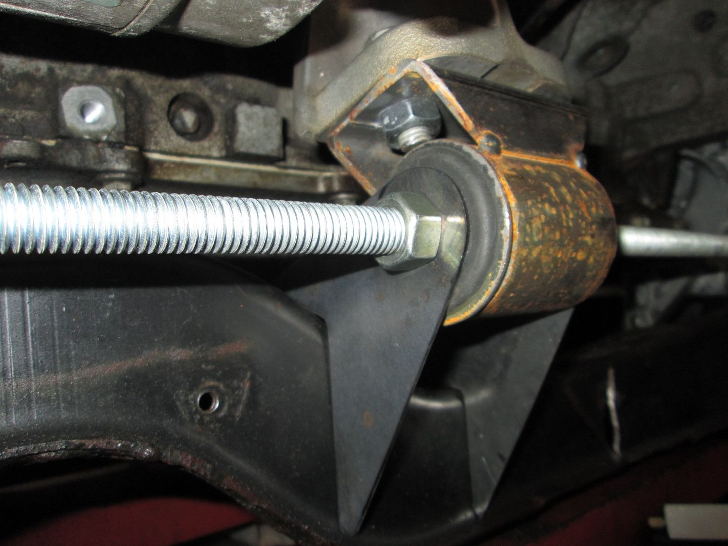
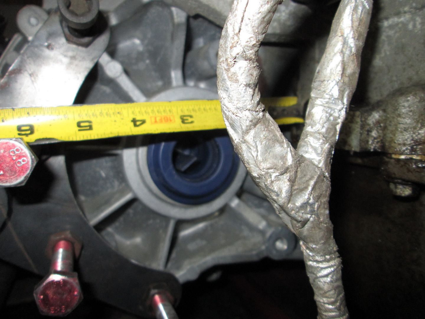
Then a little tape measure in the differential area:
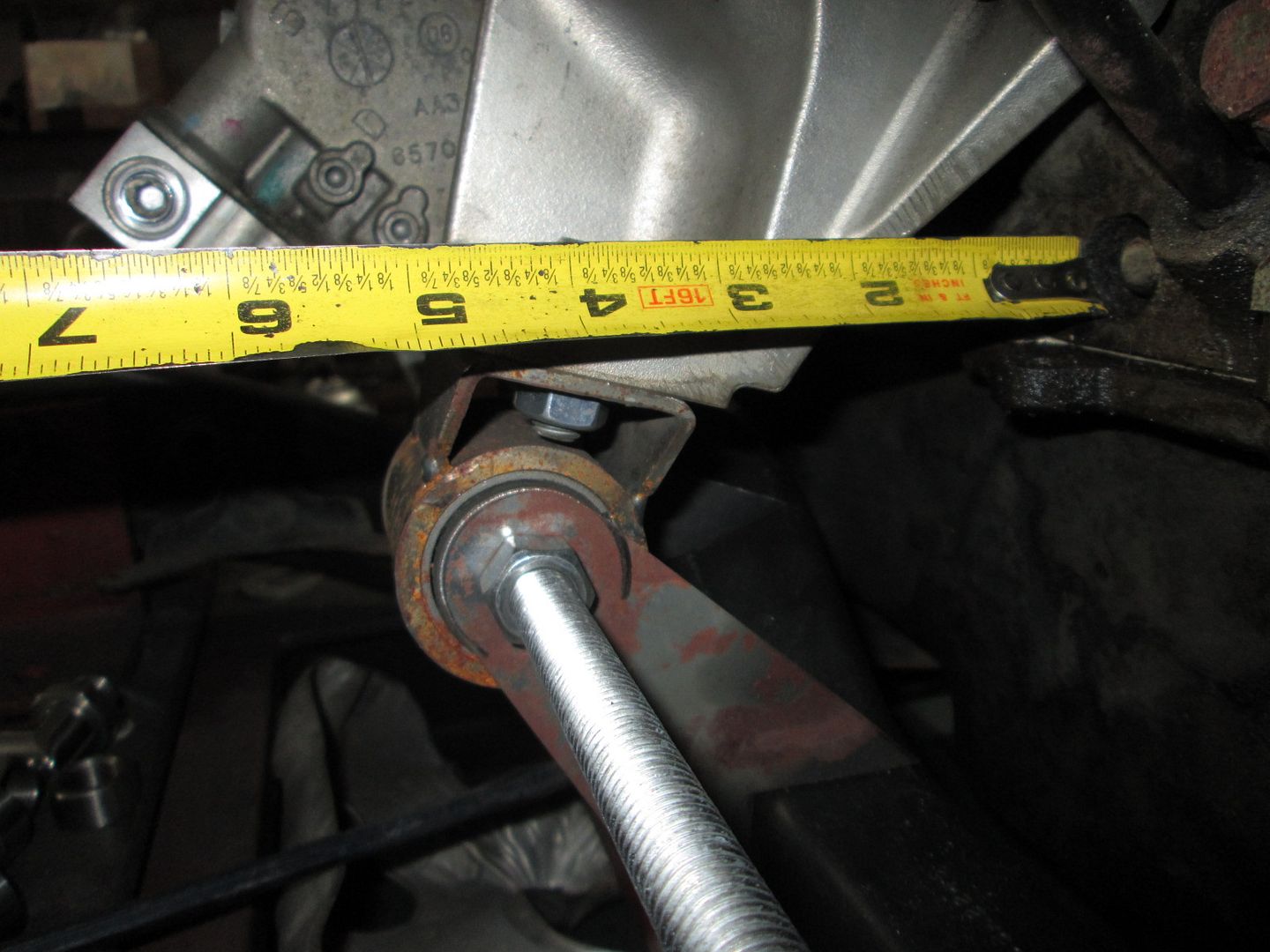
And the same on the mount - notice the tape is in line with the top of the oil pan. The LS4 flange is a couple of inches higher. :
One of these days I might pick up another set of LS7 manifolds for an official test fit.
[This message has been edited by fieroguru (edited 08-23-2016).]
I'm getting ahead of you, but you must have a plan in your head for the water pump and FEAD, right?
All that I "know" right now is that I will not be doing it the same way as I did my first one... way too much fab work. The fall back position is a front mounted electric water pump and a simple water manifold setup in the rear, but I haven't given up on creating a mechanical pump solution... The LS4 alternator also doesn't have real handy mounting tabs, but I would like to keep it as well to help keep overall costs down.
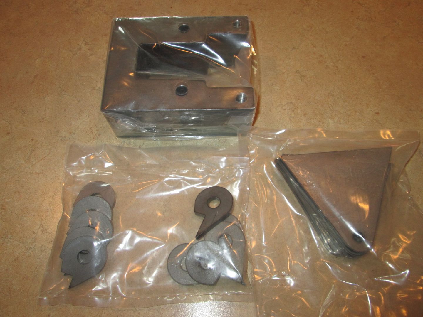
This is my super busy time at work, so I haven't done much with this project except unpack these (the last 2 wear strips should arrive this week, as well as full set of 2009 Cobalt SS Turbo axles).
[This message has been edited by fieroguru (edited 10-04-2016).]
Originally posted by ennored: The new LT stuff ends up too far from the block I assume? Never mind that it doesn't actually bolt on an LS without some work.
It doesn't bolt onto the Gen III/IV engines even with work. You'd need adapters, as the ports are different, which would only move the pump even further out. And yeah, the Gen V engines all have VVT which means the water pump is already too far out for the LS4 serpentine.
I already looked at that as a possibility for my build, as I'm retrofitting VVT, but the ports are rotated 90 degrees, and I think the bolt holes might be moved as well. I also wanted to use the Gen V oil pump, but it similarly has some incompatible changes to port alignment.
The new LT stuff ends up too far from the block I assume? Never mind that it doesn't actually bolt on an LS without some work.
(This being a truck V6 setup. The car stuff puts the waterpump on the other side, that'd never work.)
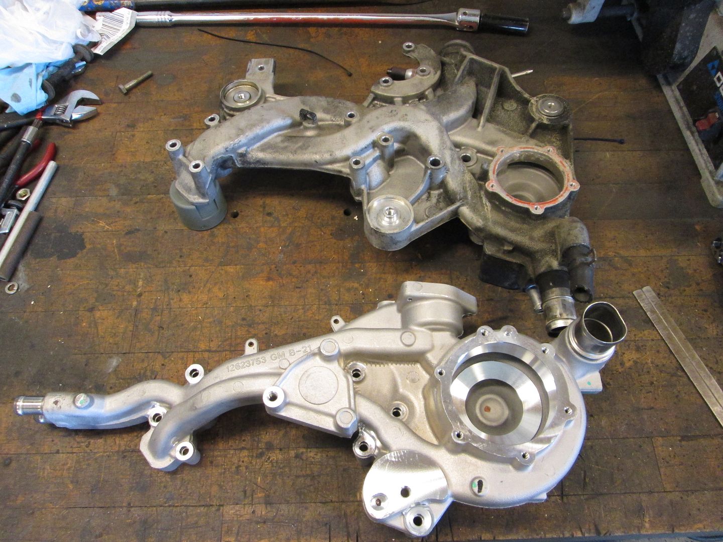
I have had one of those LT 4.3 pumps for over 2 years, which is when I took all of these pictures. The pump is still in a storage tub from moving:
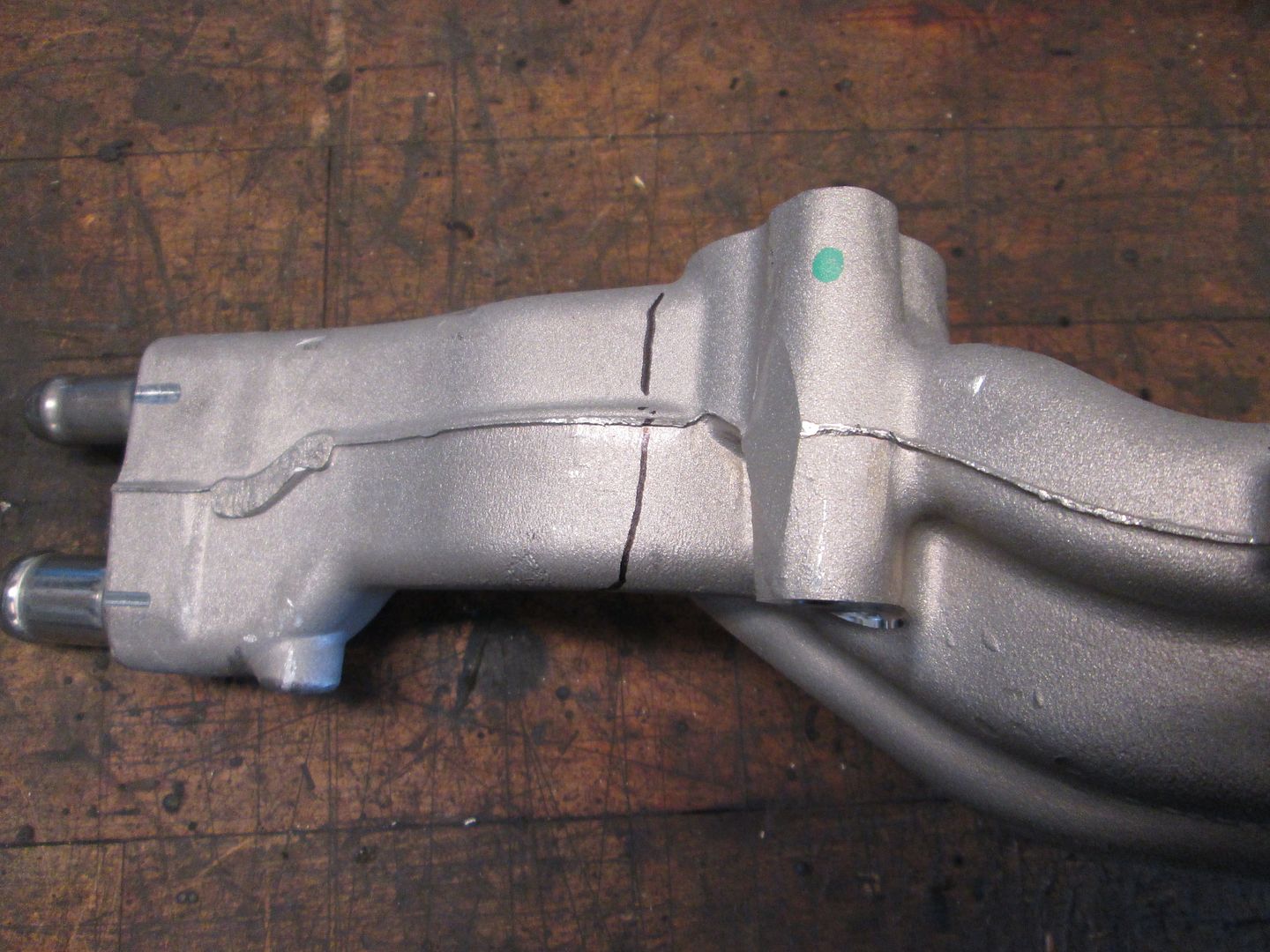
The heater ports would need to be cut off and pluged and at least 1 new port location identified:
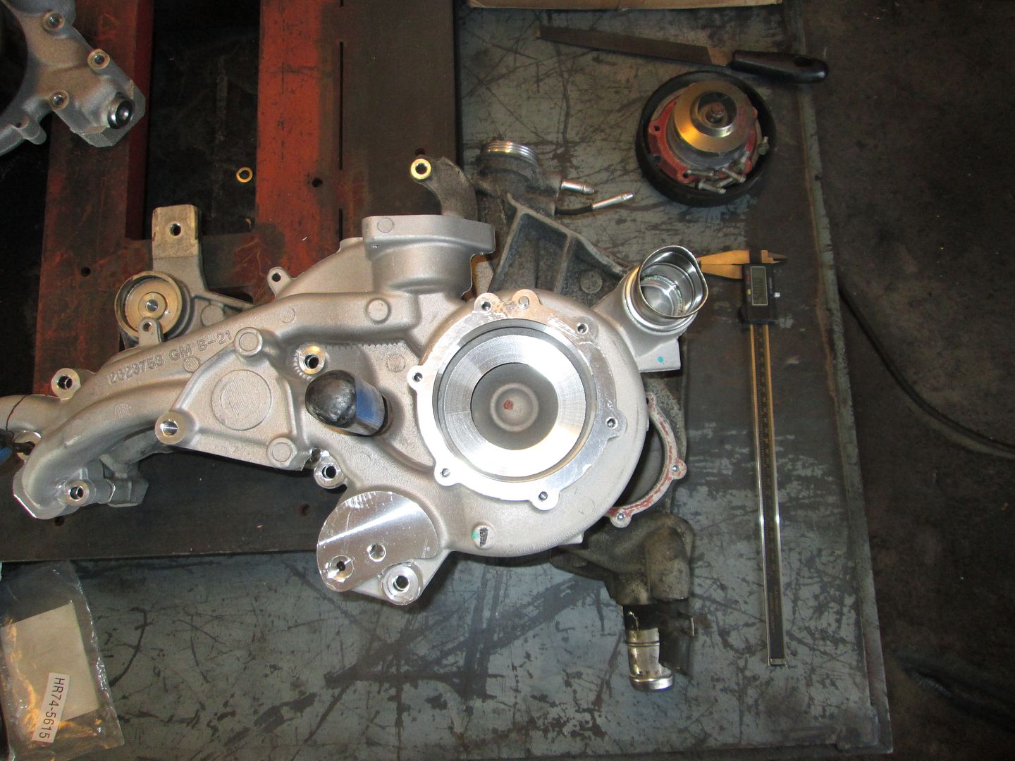
The bolt pattern is the same, the only difference is the ports, but either with a thin metal gasket or some aluminum welding to the housing you could seal up the ports.
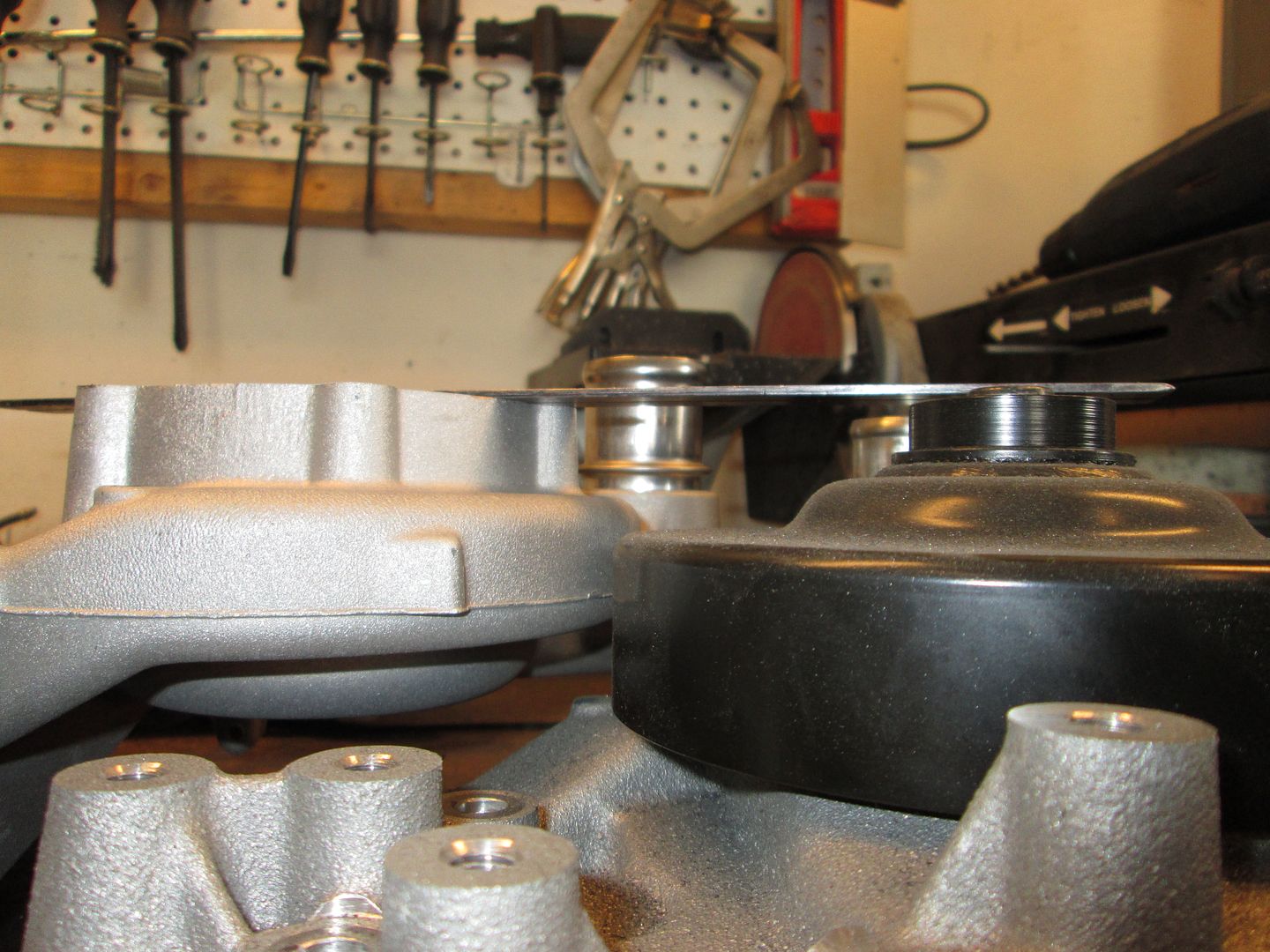
The real issue is the depth of the pulley and the available room. The black pulley in the picture is from an LS3 water pump and it is 4" from the outer belt edge, so this LT pump will have the outer belt about 6".
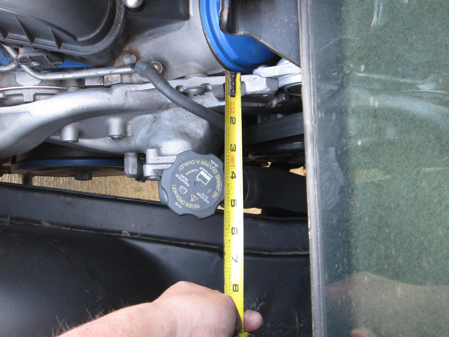
Here is the available room in the chassis...
There are a few other modifications to the pump that could likely get it to fit within the frame rail, but then how do you drive it? If the balancer stuck out that far it would require a large frame notch. Another option is to make a custom dual pulley setup for the alternator... either way it isn't a low modification solution, so it hasn't been given the green light.
[This message has been edited by fieroguru (edited 10-05-2016).]
I know its been said before, I think in your last build, but I like the way Archie does it for the LSX swaps. I like how simple his solution is and its easy to modify/change what he does if you want a clean(er) look. I cleaned mine up and I've seen a few others installs where the builder changed it around a little to fit their style. I've wanted to do a LS4/auto for a daily driver for years and I know if I ever do one, I'm going to go with the "Archie" style solution. I know you know this but for the benefit of others reading this if you look up "LS remote water pump adapters" you will see a few different parts to assist w/ this project.
BTW - Guru, I still may have a line on two sets of LS7 exhaust manifolds if you want. I work w/ a guy who has done a few LS7 swaps and does not use the manifolds.
Originally posted by qwikgta: I know its been said before, I think in your last build, but I like the way Archie does it for the LSX swaps. I like how simple his solution is...
I know that way works, but part of the fun/challenge in all my swaps is to find another creative solution. So I will only go electric if all of my other thoughts on a mechanical water pump fail...
[This message has been edited by fieroguru (edited 10-09-2016).]
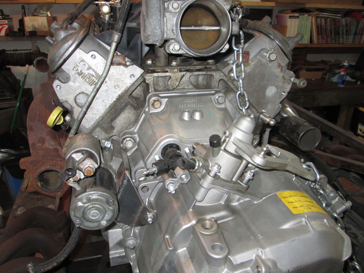
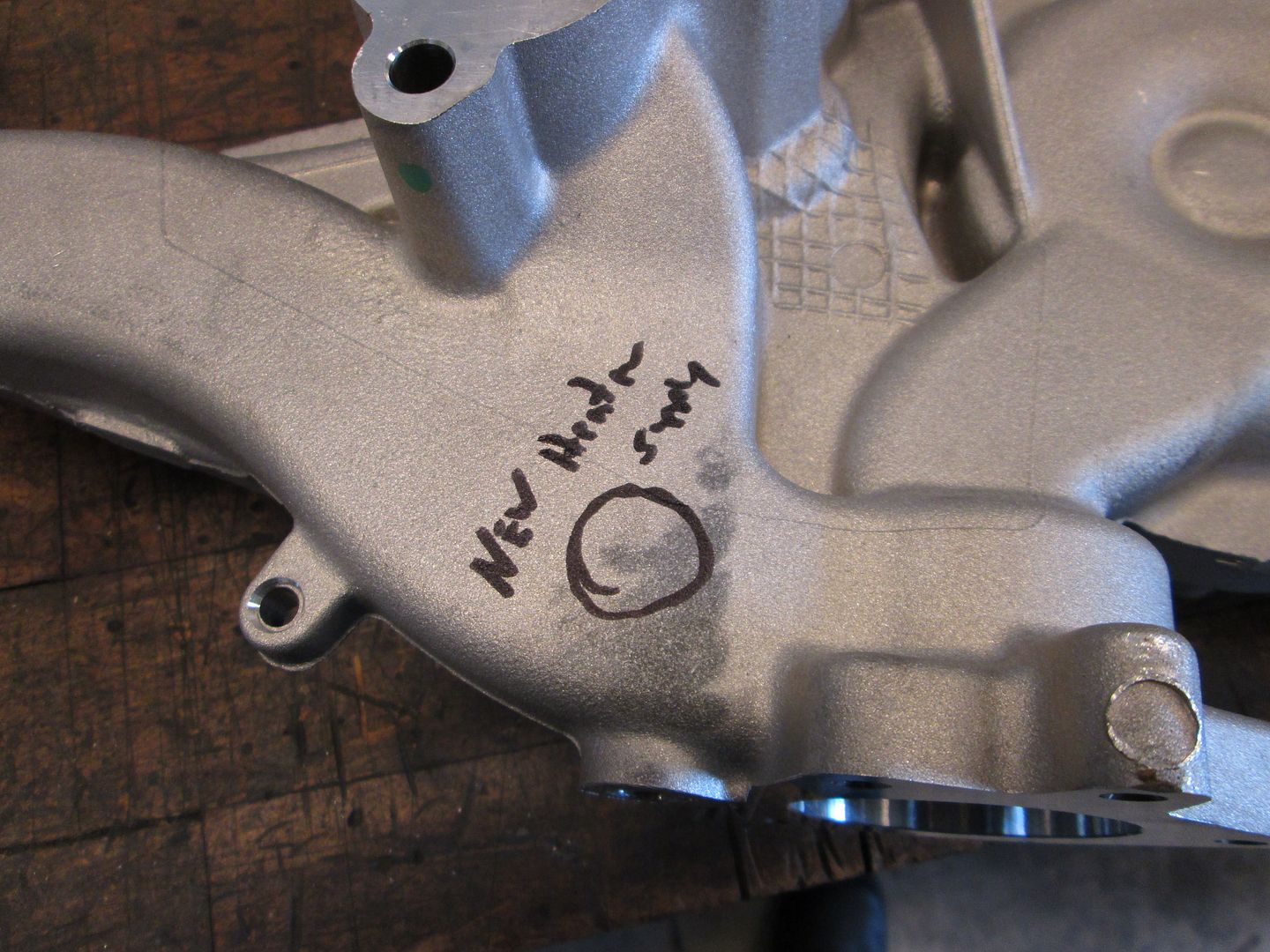
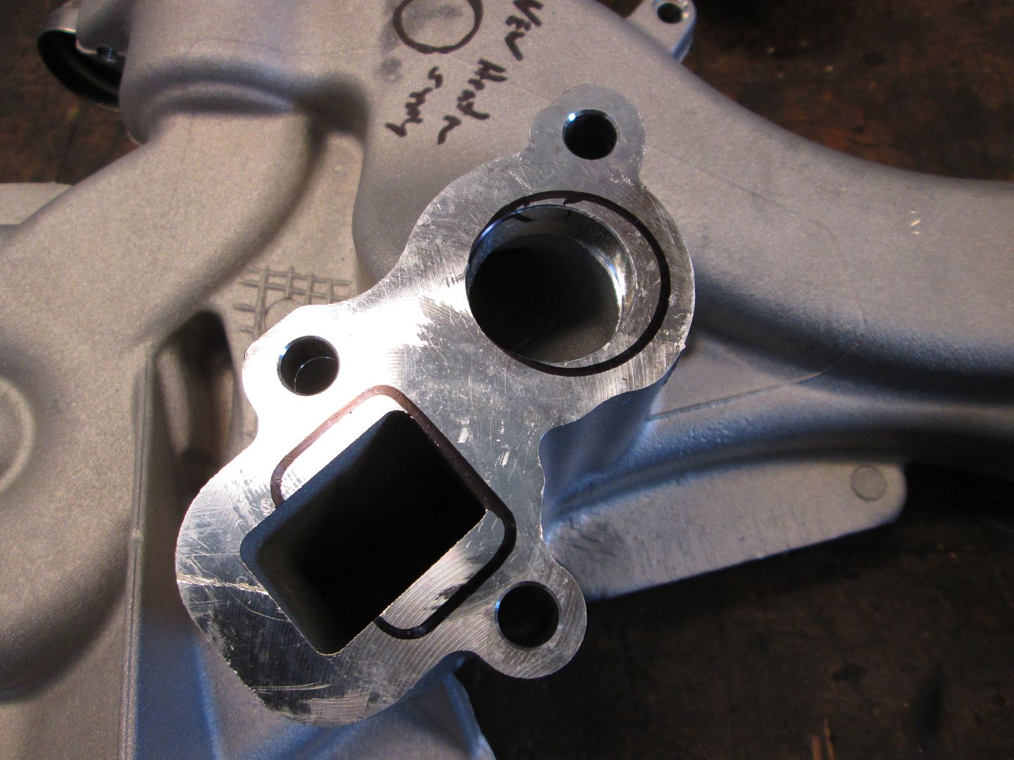
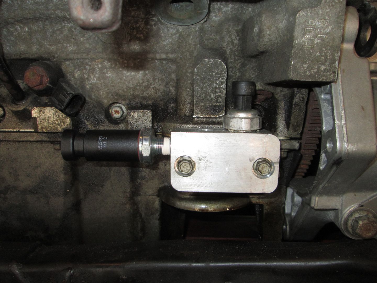
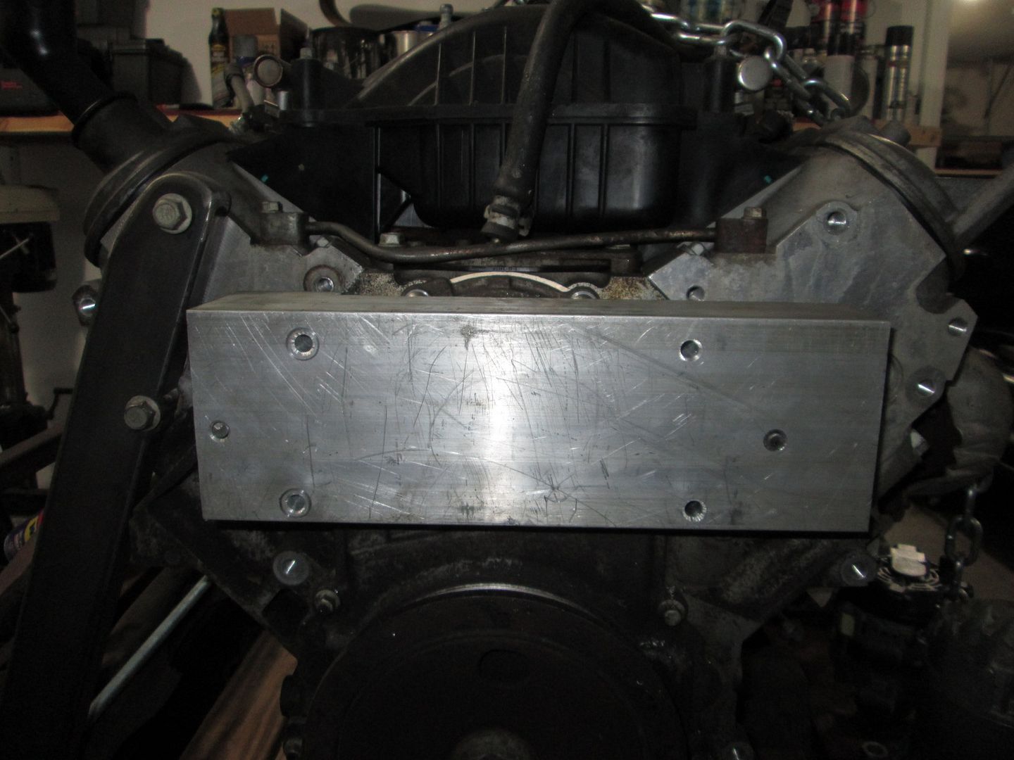
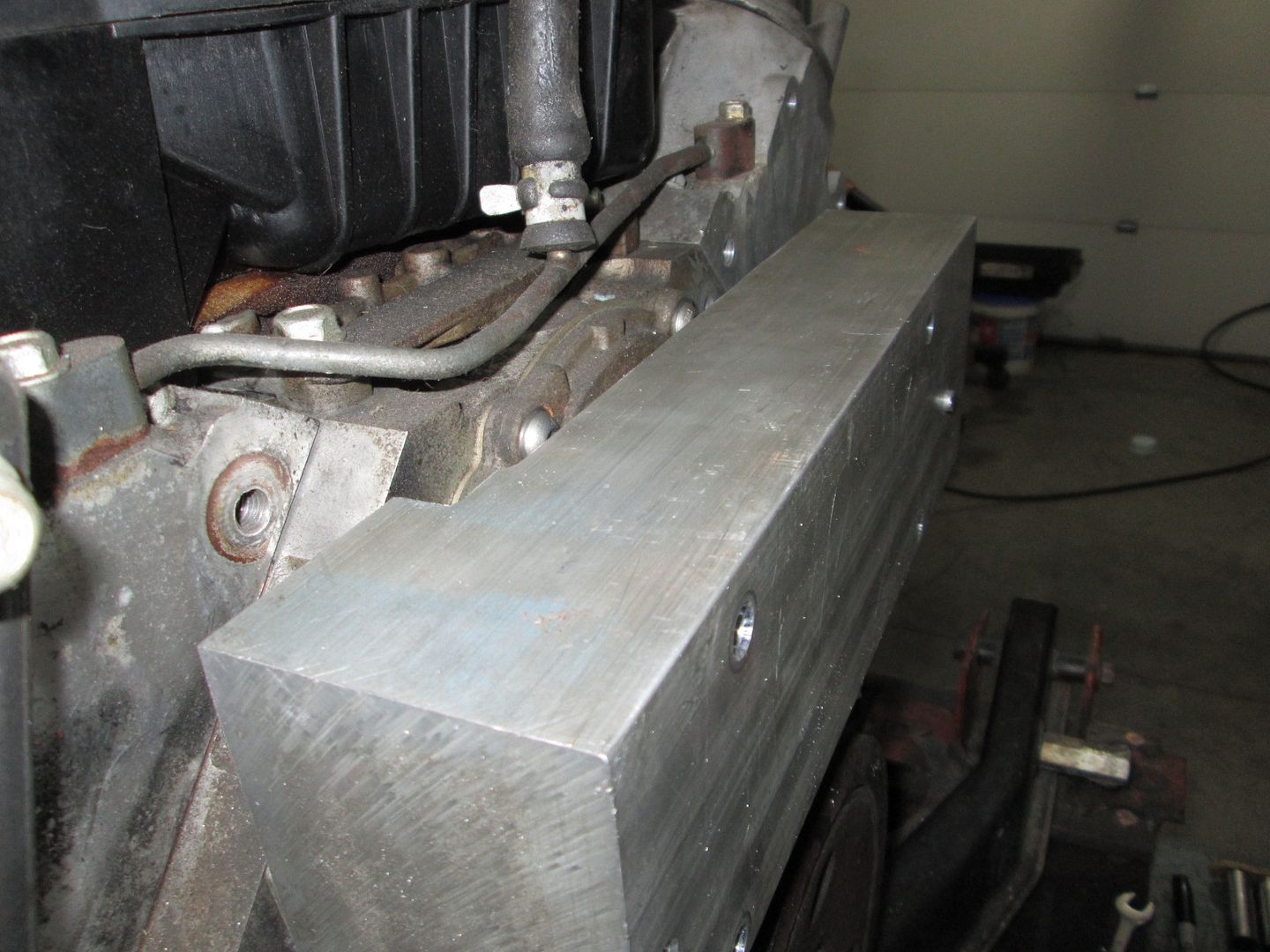
Today, I made a new oil bypass cover. This one has 3 tapped ports, 1 for the Fiero oil gauge sender, 1 for the LS4 oil pressure sender, and 1 additional tapped port (oil supply for a turbo?) There is plenty of material to add another port or two if needed.
Those that choose to keep the stock LS4 intake, won't need to relocate the LS4 OPSU, but if they do want to swap intakes, this will greatly simplify the process and it moves more stuff with wires to a non-visible location.
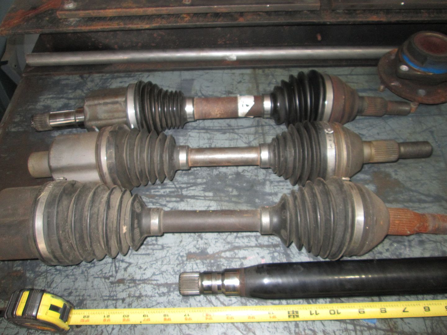
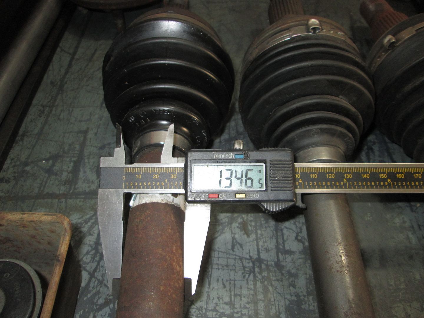
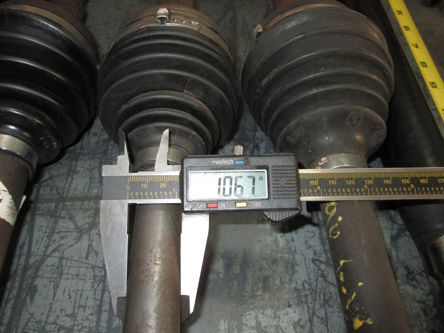
I also unwrapped the 2009 Cobalt SS Axles. The middle section is much larger than the G6 axle, curious if they stay that thick all the way into the tripod and CV sections: The cobalt axle is at the top, the F40 G6 one is in the middle:
I know that way works, but part of the fun/challenge in all my swaps is to find another creative solution. So I will only go electric if all of my other thoughts on a mechanical water pump fail...
Are you going to try to make the stock LS4 manifold fit, with minimal modification? I think the simplest I've seen is the one Rickady88GT did, where he only cut off part of the area that interferes with the firewall, moving one of the idler pulleys, and relocated the passenger side decklid hinge. It's too bad none of the aftermarket pumps have the inlet/outlet both on the #1 side. A simple bolt-on billet option would be nice. I've been thinking about how best to make something similar to the Gen V truck manifolds, but that snugs up closer to the block, and doesn't have the heater connections on the #3 side, for my swap, since I'll have VVT.
Originally posted by dobey: Are you going to try to make the stock LS4 manifold fit, with minimal modification?
Nope. Using the stock LS4 water pump setup is 2nd to last on the list with the electric water pump setup being last. It is just too much of a space hog and greatly complicates the placement and work associated to find the alternator a new home.
quote
Originally posted by dobey: A simple bolt-on billet option would be nice.
This is one of the paths being explored. I have the upmost confidence there is a solution here, the challenge will be to make it cost competitive vs. the other options.
any work on the 4T65E-HD swap? Still want to do an LS4 for my daily driver. I have the 3800-auto trans in my car now and I kind of like the auto. Still love the LS3/F40 for fun, but daily traffic sucks w/ that car.
any work on the 4T65E-HD swap? Still want to do an LS4 for my daily driver. I have the 3800-auto trans in my car now and I kind of like the auto. Still love the LS3/F40 for fun, but daily traffic sucks w/ that car.
Rob
Nope. It is sitting under the metal work table, but all my free time is being dedicated to the LS4/F40 development and the turbo upgrade. It will likely a year before I get back to it, however, many of the parts I am developing will carry over to the auto swap as well.
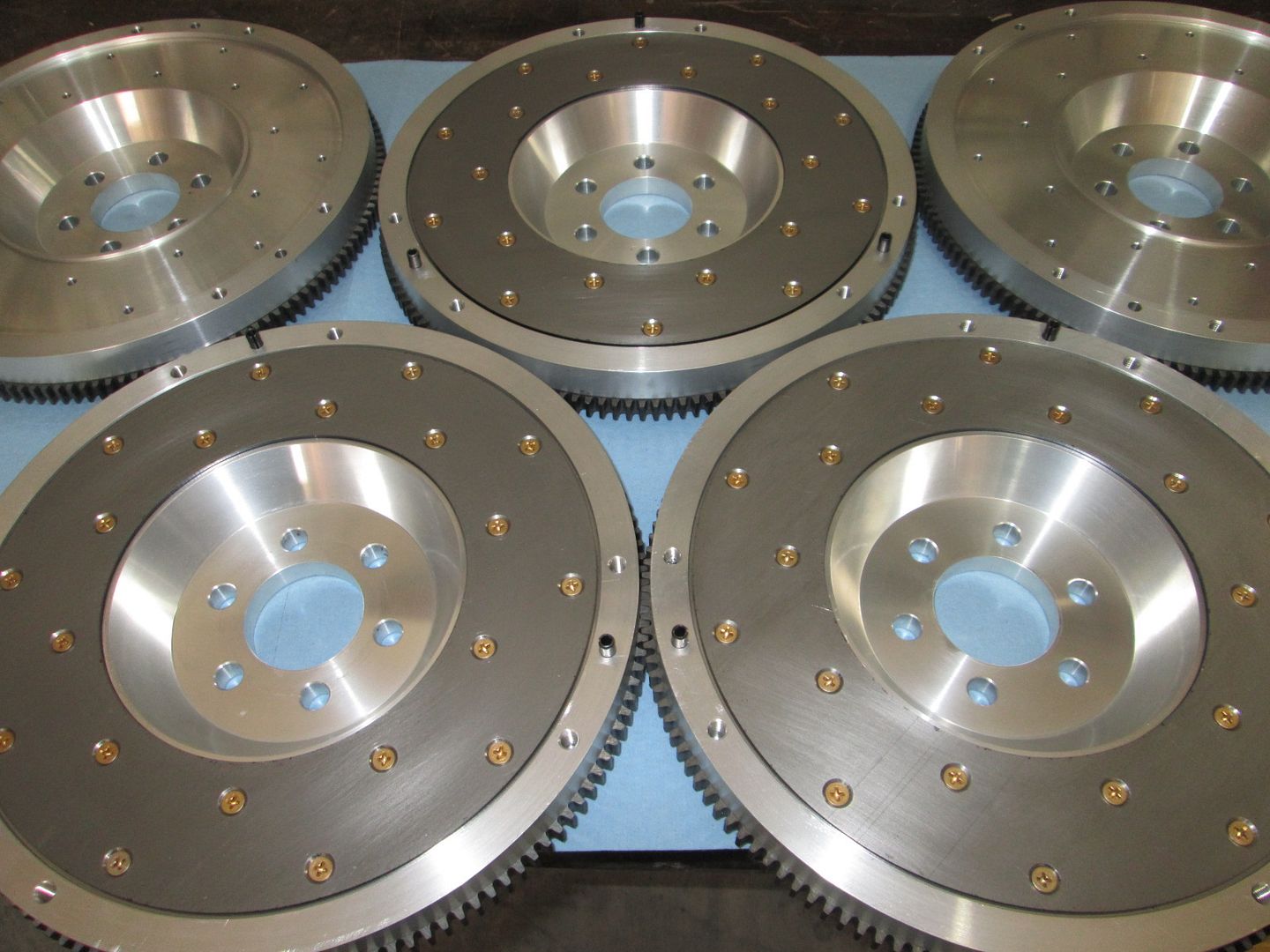
All 5 LS4/F40 flywheels and even more starter mounts sold during my week long sale! So the only flywheel I have left in stock is the one for this swap.
If anyone is still looking for a flywheel, let me know and if there is enough interest I will do another production run.
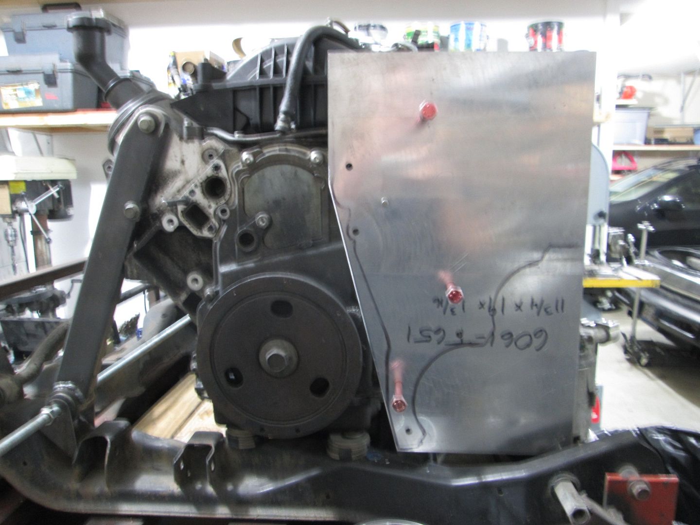
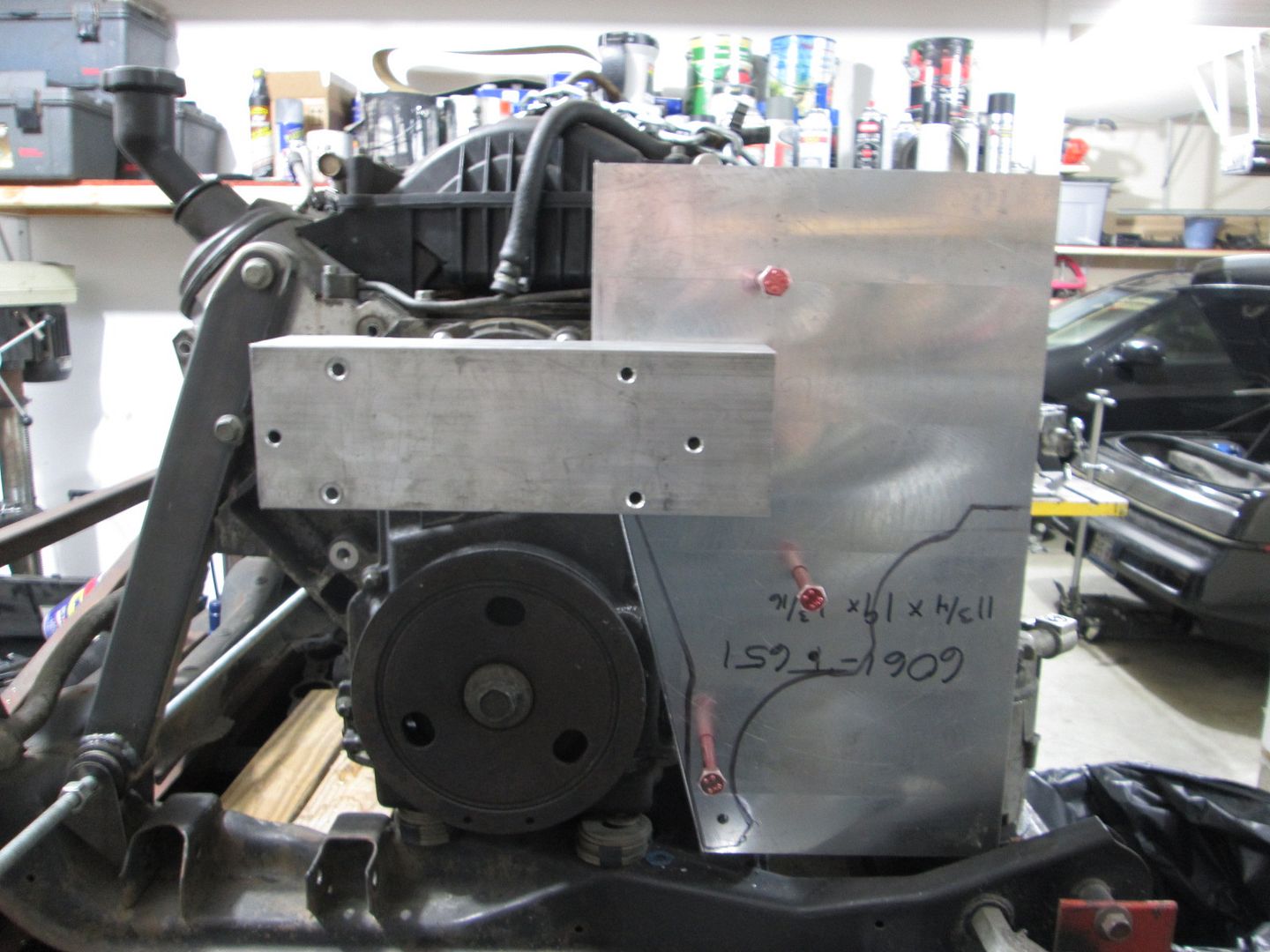
I have lost track how many times I have mocked up the AC, Alternator, Exhaust and tried to fit a stock water pump somewhere in the mix... All this effort lead me to find what I believe is the sweet spot for the AC and alternator positions, which leaves just enough room for a water pump insert in a custom water pump manifold setup.
I have started the process of making the main accessory bracket and water pump housing, but still have a lot of aluminum to remove... All this effort is mainly proof of concept and when the time comes to have the parts CNC machined I will likely tweak the design to make that process quicker/cheaper... no one wants a $600 water pump.
Glad your making some progress here. Is the cnc water manifold going to use a common off the shelf pump or ls4 pump just in a different area of the manifold you are designing? I was really biting my nails on black friday and almost pulled the trigger on one of those flywheels. After Christmas I' m game on one send me a pm if you need a deposit or something to get the ball rolling. I' m hoping you eventually offer a kit for the trans and engine mounts at some point. Keep up the good work!
are you building the new water pump and accessory setup for the turbo car?
The intent is to build something that will expand my LS4/F40 product line so they will eventually be available for purchase.
This new accessory bracket will likely not fit the current bracket/front engine mount setup in my current LS4/F40 swap, so its not like I can just swap it in for testing on the car that will eventually be turbo'd... but I do want to test and verify function of the water pump setup.
The turbo setup will require a new air intake, intake manifold, injectors, fuel rail/regulator, camshaft, exhaust manifolds, exhaust, etc... so instead of having all these parts left over, I could have 2 complete and running LS4/F40 swaps. I don't have a Fiero for the 2nd setup yet, but its not hard to pickup another 88...
All 5 LS4/F40 flywheels and even more starter mounts sold during my week long sale! So the only flywheel I have left in stock is the one for this swap.
Hi Guru,
This might be a dumb question, but who is buying the flywheels and starter brackets when you still haven't sorted out all the details of this swap? I'm waiting for the final kit, but parts are already sold out. I'm confused.