I take it completely out. just keep a list of all the systems you removed. ie. egr, and auto trans. and purge, and so forth. so when you send the guy the pcm to be tuned he will know what exactly to do. that's so you won't end up with a nonstarting motor or a forever ses light. just because the man was misinformed.
IP: Logged
10:57 PM
Mar 10th, 2012
FieroDev Member
Posts: 246 From: Regina, Sask, Canada Registered: Jan 2010
Thats a good idea, on the pin-out diagram i highlighted all the pins i deleted, i think i'll make the list and also send the pin-out sheet showing what i took out. Dev
IP: Logged
01:45 AM
Mike Gonzalez Member
Posts: 5093 From: Colorado Springs, CO. USA Registered: Jul 2001
I like to dissasemble the 3800 harness completely leaving full length wires on each connector all the way to the PCM pins if they have them. Cut out all the splice packs for power, ground, and 5v, then wrap all the connectors up so they are organized. The start assembling the new harness one connector at a time shorteniing or lengthening the wires as needed. Trying to work with the original harness stil partialy in tact makes for a lot of headaches in m opinion. PM me anytime if you need any help....I have been away from here for a while due to personal reasons, but im itching to get involved again ! Good Luck !!
IP: Logged
09:58 AM
Ryanstalin Member
Posts: 300 From: Phenix city, Al, usa Registered: Jan 2012
I wouldn't disassemble it entirely. you can still trace all your wires with the pins still in. just confirm the pin number, and the color of the wire. then follow the wire to wherever it ends up. the wires are stuck together even with the tape removed. so you will be doing a lot of pulling apart.
I wouldn't disassemble it entirely. you can still trace all your wires with the pins still in. just confirm the pin number, and the color of the wire. then follow the wire to wherever it ends up. the wires are stuck together even with the tape removed. so you will be doing a lot of pulling apart.
Ya, one does not "need" to remove all the individual wires, but it sure makes the install ALLOT cleaner! It gives you the option to run the wires/loom in a different direction/path than stock 3800; making it more sutable for a Fiero engine bay.
Also, when making up your harness, try to plan 3-4 steps ahead, don't tape anything up until everything it run to where you want it...
Im in the process of doing a 3800 swap myself. I have deleted the: Boost bypass EGR O2 sensor bank 2 Autotrans 180 thermostat As for the evap purge solenoid im going to run the unboosted vacuum off the top of the motor to the solenoid then run one line from solenoid to both connectors teed together on the canister. I dont know if the pcm will still be able to control the purge soldenoid without the fuel tank pressure sensor or if the evap solenoid is turned off and on periodically, maybe someone can chime in
IP: Logged
05:59 PM
phonedawgz Member
Posts: 17106 From: Green Bay, WI USA Registered: Dec 2009
Usually the vent of the EVAP canister is left to the open air.
The purge of the EVAP canister should run to the EVAP solenoid. The other port of the EVAP solenoid should run to a vacuum source between the SC and the throttle body.
The PCM should be programmed to not run the vent valve and fuel tank pressure test.
So what sensors do i need to replace? i know the oil pressure sender, (what do i do to wire it in?) and i remember hearing something about a coolant temp sensor, can anyone confirm? Dev
So what sensors do i need to replace? i know the oil pressure sender, (what do i do to wire it in?) and i remember hearing something about a coolant temp sensor, can anyone confirm? Dev
Dev, use the search function; these questions have been asked and answered many times in the past. There are threads started that have full wiring diagrams in them for every wire...
So what sensors do i need to replace? i know the oil pressure sender, (what do i do to wire it in?) and i remember hearing something about a coolant temp sensor, can anyone confirm? Dev
You need to use a 3 pin oil pressure sender, the same part number that is used for the 88 2.8 Fiero.
You also need to use a 3 pin CTS/Gauge Sender combo. Usually the 3800s come with the 3 pin CTS/Gauge Sender combo.
====
quote
Originally posted by ALJR:
And this is something that is programed into the PCM?
Yes
IP: Logged
08:19 PM
Mar 14th, 2012
Terry_w Member
Posts: 930 From: Fort Worth,TX Registered: Sep 2008
Another thing, how much of the GTP harness do I take? seeing as im not using the 4t60e do i just take the harness that goes with the motor? Dev
I know you don;t plan on using it so it doesn't matter to the swap but if the transmission is good and you sell it the GTP would have a 4t65HD not a 4T60E. I don't think those have been used since about '97
IP: Logged
12:15 AM
May 2nd, 2012
FieroDev Member
Posts: 246 From: Regina, Sask, Canada Registered: Jan 2010
Again on the EVAP solenoid, not to hijack the thread but what is defined as a cruise condition? Sustained throttle position and vss inputting constant speed? In a stick swap is the pcm still able to know when the car is cruising
IP: Logged
12:42 PM
FieroDev Member
Posts: 246 From: Regina, Sask, Canada Registered: Jan 2010
Now im just wating on getting a computer back from dan (mine got lost in the mail on the return trip). I have questions regarding vacuume lines and my fuel pump.
Where do i run these vacuume lines?
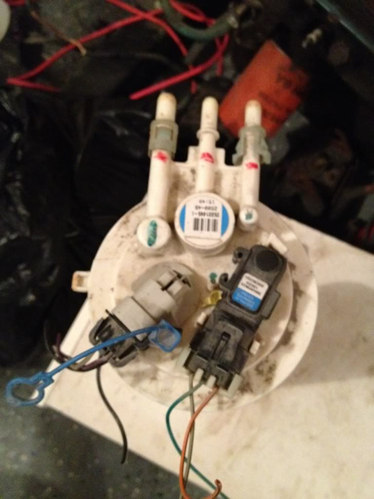
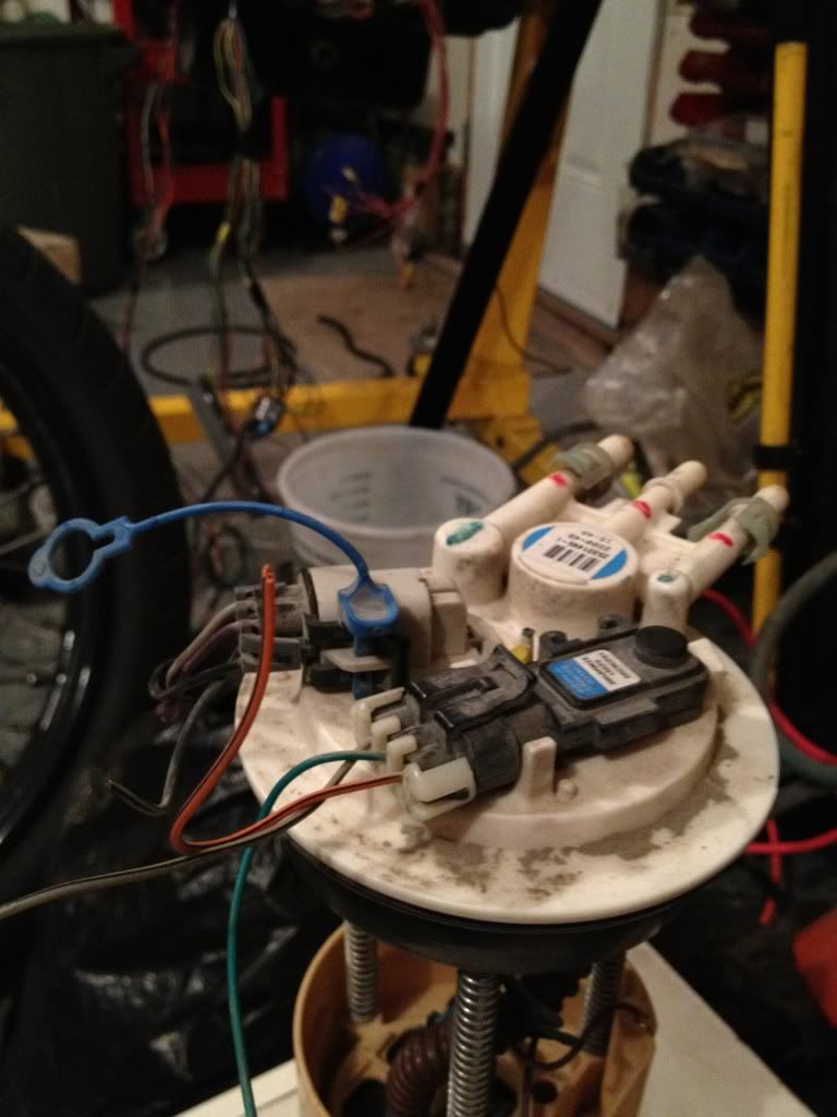
And then with the fuel pump, can anyone tell me what wire goes where? its the stock fuel pump out of the 2001 GTP
IP: Logged
01:14 AM
Mike Gonzalez Member
Posts: 5093 From: Colorado Springs, CO. USA Registered: Jul 2001
The one on the TB I run to the brake booster, I cap off the ones on top of the supercharger, and then run the MAP and FP regulator off the one under the SC snout. Cant help on that fuel pump, I always replace the Fiero one with a AC delco EP381.
[This message has been edited by Mike Gonzalez (edited 05-29-2012).]
IP: Logged
01:25 AM
phonedawgz Member
Posts: 17106 From: Green Bay, WI USA Registered: Dec 2009
+1 on using the stock Fiero fuel level sending unit / pump bracket.
On the thing you have in the pic - The sensor to the right is a pressure sensor - used to determine the integrity of the fuel tank. That is so it is known the tank is not leaking out fuel fumes and polluting. That sensor is not used on a Fiero 3800 conversion (If you try to use that pump assembly)
[This message has been edited by phonedawgz (edited 05-29-2012).]
IP: Logged
04:21 AM
May 30th, 2012
FieroDev Member
Posts: 246 From: Regina, Sask, Canada Registered: Jan 2010
Have used a threaded to 5/8" barbed fitting in brass from home depot, made by shark bite. then a 90° 5/8 barbed elbow also from shark bite. Run it straight to the firewall then down.
IP: Logged
02:24 PM
Jun 29th, 2012
FieroDev Member
Posts: 246 From: Regina, Sask, Canada Registered: Jan 2010
Got it running and driving today and I love it! Just one problem, the battery isn't charging properly, can anyone confirm my wiring? I have the thick wire from the alternator to the block under the c500, and then another wire going to 12 volt power from the block, is that correct?
IP: Logged
04:25 PM
ConvictedRedneck Member
Posts: 1034 From: Easton, PA - USA Registered: Nov 2005
Got it running and driving today and I love it! Just one problem, the battery isn't charging properly, can anyone confirm my wiring? I have the thick wire from the alternator to the block under the c500, and then another wire going to 12 volt power from the block, is that correct?
Wait, you have a positive going to the block??
IP: Logged
05:19 PM
phonedawgz Member
Posts: 17106 From: Green Bay, WI USA Registered: Dec 2009
Got it running and driving today and I love it! Just one problem, the battery isn't charging properly, can anyone confirm my wiring? I have the thick wire from the alternator to the block under the c500, and then another wire going to 12 volt power from the block, is that correct?
Yes that is correct, I assume the "block" you are talking about is the power distribution block near c500. On the alternator there is another connector that should have 1, 2, or 3 small wires. The red one should be going to your PCM, Then there is a pin from the PCM that should go to c500 for the alternator/charge light.
IP: Logged
08:26 PM
FieroDev Member
Posts: 246 From: Regina, Sask, Canada Registered: Jan 2010
Make sure the small red wire on the 4pin connector has 12v with the key on. If it does it should be working. Should have about 14v on the big red wire with the engine running.
IP: Logged
09:56 PM
Jul 1st, 2012
FieroDev Member
Posts: 246 From: Regina, Sask, Canada Registered: Jan 2010