I just got a 3800 (75k)and its mateing to a 92 FWD Getrag 5 spd.I have a couple of questions that I cant find the answers to on here.
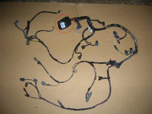
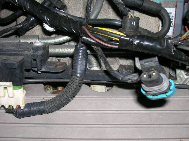
Heres a picture of the harness I have and was told that the plug in the red circle was for the automatic transmission and someone else said it sounded like it went to the fuse box. If it is for the tranny then I should be able to remove this plug and all its wires.
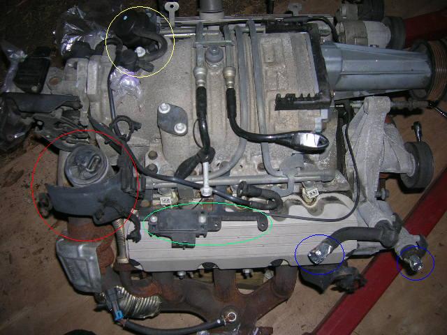
Also I see most builds remove alot of extra things that are not needed after swaped over. Most keep the vacume setup for the SC in the yellow circle but can I do away with the red and green circle? I would like to keep it as clean and easy as possible without causing problems down the road.
And I assume that the blue circles go to the heater core.
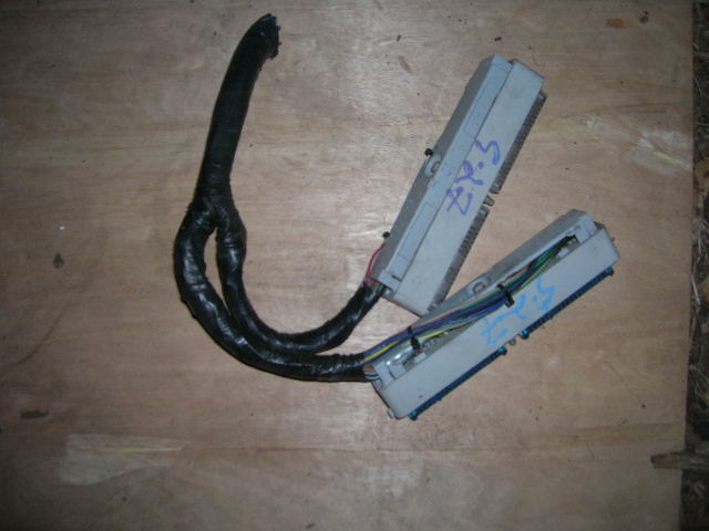
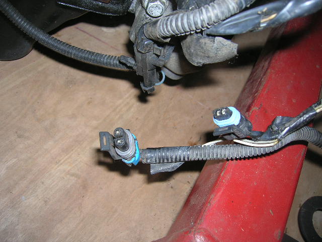
This is the rest of the harness I have with about 8 inches of wire on them.
I have the color coded pinout but to be sure, am I replacing the plug in the center console to the ecu with one of these or where do these get wired to? I dont have the OBD2 yet.
Once I get this straight, I hope to make a informitive thread with pics on this to make it easier to understand.
Also if I seem to be missing something or you have any suggestions, please let me know.
Thanks, Steve
IP: Logged
05:54 PM
PFF
System Bot
Riceburner98 Member
Posts: 2179 From: Natick, Ma, USA Registered: Apr 2002
I'm pretty sure the big connector in the red circle in the first picture is the firewall connector. That kind of connects the engine harness to the inside of the car / PCM.. The auto trans connector should be a 1-1.5" round plug with a bunch of pins. You can get rid of the EGR setup (other red circle, attached to the exhaust) if you program the error codes out of the computer, but you don't want to get rid of the MAP sensor (green circle next to the red one) as that's how the PCM knows the vacuum of the engine.. Blue circles go to heater core. Yellow circle is vaccum connections and boost bypass valve. Most people modify both those to their taste, some prefer ditching the bypass and blocking it "open", others keep it..
IP: Logged
06:45 PM
Dennis LaGrua Member
Posts: 16072 From: Hillsborough, NJ U.S.A. Registered: May 2000
I'm not sure that I understand all the questions. Red circle is EGR , green is MAP snsor ( must be retained). if you have an 87 the heater core support is supplied by the connection under the manifold while the other connection at the water pump is capped off. If you have an 85 or 86 Fiero then the return will use the connection to the water pump. Who supplied that harness and why did they cut the Blue and Clear PCM connectors from it? If you are starting a harness build from scratch then you need to figure out what you will keep and what you won't use. Automatic or Manual swap, BBV or delete, EGR or delete, AC PCM driven w sensor ( as in my approach) or basic Fiero A/C control, etc etc. The you wire up your fuel pump and A/C relays, connect power and ground, wire in the gauges and a few other items and it should work.
------------------ 87GT - 3800SC Series III engine, 3.4" Pulley, N* TB, LS1 MAF, Flotech Exhaust Autolite 104's Custom CAI 4T65eHD w. custom axles, HP Tuners VCM Suite. 87GT - 3.4L Turbocharged engine, modified TH125H " I'M ON THE LOOSE WITHOUT THE JUICE "
[This message has been edited by Dennis LaGrua (edited 12-07-2008).]
Dennis they didnt cut the blue and clear connectors off. That a buick harness where the plug in the 1st pic goes through the firewall an to the c1 and c2. You have to cut that plug off but it does not go to the transmission. It doesn't look like you got the automatic transmission plugs with that harness. Your going to have to lengthen all the wires to the pcm. You'll keep the clear plug (c203) in the bottom pic but you wont use the old ecm connectors. You can do away with the bbv (yellow circle), the egr (red circle), heater core(blue circles) but you have to keep the map (green circle). You will also reuse the connector you have marked #2 that is the c500.
IP: Logged
07:50 PM
Dec 8th, 2008
JumpStart Member
Posts: 1412 From: Central Florida Registered: Sep 2006
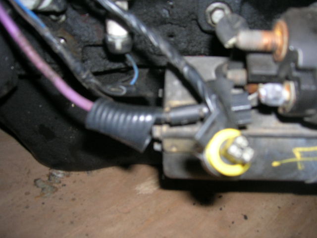
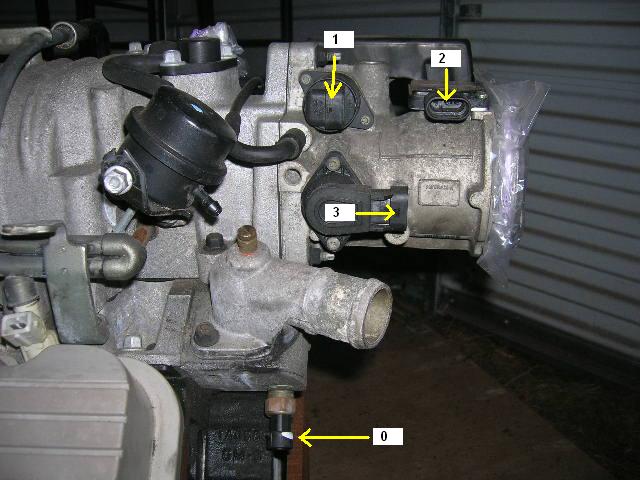
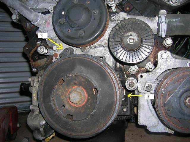
Ok, I removed the exhaust and doing away with the EGR. I noticed that to the right of the MAP sensor in pic 2 that it looks like something else was there with the same screw holes as the MAP.
What was there? And I guess I just plug the EGR hole in the intake, correct?
EDIT: I think im seeing what I need to do now. From what I can tell, the block in pic 1(red circle) contains all the wires for the 3800 engine harness. What I need to do is remove these wires from the block and these wires will be connected to the blue and clear connectors in the 3rd pic(replacing the ECM plug behind the console), the c500 (2.8 harness wires are removed from the c500 plug and replaced with wires on the 3800 harness) And a few left for the ALDL,AC,fuel pump ...ect...
So the only plug on the Fiero that is not used would be the ECM plug? Thanks, Steve
[This message has been edited by JumpStart (edited 12-08-2008).]
Completely remove The Fiero engine harness to make things easier then just wire up your harness so the wires with the C203 and C500 will reach back to their proper positions. The reason your PCM connectors are seperate is some of the earlier OBD II cars still kept the PCM mounted inside the car making these harnesses a little harder to work with then the ones that mounted the PCM in the engine compartment. The extra mounting point on the MAP sensor bracket is for mounting a second MAP sensor to run a boost gauge like the SSEi Bonnevilles had, the 96 and 97 models also had one of the EVAP solenoids on the bracket as well. You can remove the bracket and mount the MAP sensor else where if you like as long as it is still wired in and has the proper vacumm line connected to it. Just follow your diagrams for connecting the PCM connectors as well as the wiring to the C203 and C500 connectors. Dan
IP: Logged
11:16 AM
JumpStart Member
Posts: 1412 From: Central Florida Registered: Sep 2006
2 = ac pressure - basically dont need, could be used if your running a/c.
3 = magna-steer, and possibly oil switch or something. Shouldnt be a concern, assuming they are not the cam/crank sensor plugs.
You seem to be on the right track, keep plugging away. Stripping the harness down while its on the motor is a good idea, helps keep things from getting all hairy.
For BBV, to make things simple, eliminate the solenoid, and just run the top of the bbv, to the top of the blower, and disconnect everything from the bottom of the black BBV valve, leaving it open to air. This will retain full functionality, but prevent issues from the pcm wanting to pull boost for some reason (rare, and completely useless function that the pcm does, I have never ran a solenoid, but retained full valve functionality, on any of my manual cars in fear of the pcm getting confused and pulling boost.).
IP: Logged
01:12 PM
JumpStart Member
Posts: 1412 From: Central Florida Registered: Sep 2006
2 = ac pressure - basically dont need, could be used if your running a/c.
3 = magna-steer, and possibly oil switch or something. Shouldnt be a concern, assuming they are not the cam/crank sensor plugs.
You seem to be on the right track, keep plugging away. Stripping the harness down while its on the motor is a good idea, helps keep things from getting all hairy.
For BBV, to make things simple, eliminate the solenoid, and just run the top of the bbv, to the top of the blower, and disconnect everything from the bottom of the black BBV valve, leaving it open to air. This will retain full functionality, but prevent issues from the pcm wanting to pull boost for some reason (rare, and completely useless function that the pcm does, I have never ran a solenoid, but retained full valve functionality, on any of my manual cars in fear of the pcm getting confused and pulling boost.).
I will have AC...im in Florida. nuff said
As for the BBV, are you saying to just move the vacume line and eliminate the whole solenoid setup?
JumpStart, I remember when I was at this point in my swap and I had all of these exact same questions! Looks like your well on your way. I had a lot of help from this forum or I would not have known where to start. If you want send me a pm with your phone number and a good time to call. A bunch of questions can be cleared up in a quick phone conversation. (like for starters I would take both harnesses down to each individual sensor wire, move the MAP to the backside of the motor, delete all the excess wires you don't need and build a clean harness... Oh and who's re-flashing your PCM?) Good luck with it, Dwayne
[This message has been edited by Bubbajuju (edited 12-08-2008).]
The plug you are asking about could be for the high pressure cut out for the a/c. If you are going to use it that way then you'll need to read this thread dennis made about it. Otherwise do away with it and wire in the a/c like the stock fiero set up was. https://www.fiero.nl/forum/Forum2/HTML/091320.html
IP: Logged
08:59 PM
PFF
System Bot
Darth Fiero Member
Posts: 5922 From: Waterloo, Indiana Registered: Oct 2002
Also I see most builds remove alot of extra things that are not needed after swaped over. Most keep the vacume setup for the SC in the yellow circle but can I do away with the red and green circle? I would like to keep it as clean and easy as possible without causing problems down the road.
Thanks, Steve
Just my $0.02 here...
Honestly I wouldn't remove the EGR nor the BBV (boost bypass valve) setup unless you are opting for a clean look. Removing either or both of these systems WILL NOT INCREASE PERFORMANCE. Concerning the EGR system removal, the arguement can be made that one doesn't like how it looks nor wants to worry about it failing in the future. But just keep in mind if you remove this component, you will need to plug holes in the lower intake manifold and in the rear exhaust manifold if you are re-using the stocker in your swap. If this isn't done properly you can create a vacuum or exhaust leak which can cause problems.
Concerning the BBV actuator you have circled in yellow, again if you are concerned about looks and that is why want to remove it, that is a valid reason for doing so. But here again, if you remove it, you will need to come up with some way of keeping the bypass valve it actuates closed. And I have seen several methods people have come up with that didn't do the job correctly resulting in low boost levels -- so make sure you do this right or you will cost yourself power. Now just FYI: the job of the BBV and controlling actuator is to take the load off the supercharger when it isn't needed (ie: idle / low load conditions). From the factory there is a PCM-controlled component that operates with this (boost solenoid), but I usually remove that in all my swaps since it serves no usable purpose for what we are doing in the world of engine swaps -- and it can be removed without affecting the operation of the BBV and actuator. But there is no performance gain to be had by removing the BBV actuator and forcing the BBV closed. All you will be doing if you do this is just putting a load on the supercharger all the time. You don't need boost at idle nor during low load conditions so why load the supercharger (which puts wear and tear on it) when you don't need to???
-ryan
------------------ 5+ years on this same swap -- NO engine or transmission failures... Custom GM OBD1 & OBD2 Tuning | Engine Conversions & more | www.gmtuners.com
Let me tell you something about Darth Fiero, (AKA Ryan at Sinister Performance)
Darth Fiero re-flashed my PCM and I followed his wiring instructions exactly. The result of that is I have had zero problems with my swap. The check engine light only comes on when it's supposed to. (Which has only been twice, once for a bad MAP and once for a bad coil misfire) Darth Fiero replied to my countless emails about the same questions you are posting. I can't say enough good things about this guy. I should have payed him three times the nominal cost he charges to re-flash due to his support after the service.
[This message has been edited by Bubbajuju (edited 12-08-2008).]
IP: Logged
09:25 PM
darkhorizon Member
Posts: 12279 From: Flint Michigan Registered: Jan 2006
As for the BBV, are you saying to just move the vacume line and eliminate the whole solenoid setup?
Thanks, Steve
I suggest solenoid removal yes, it cleans up some, and decreases 1 more wiring issue, and doesnt hurt the performance of the BBV at all (for sure keep the BBV setup as ryan suggested also).
Your AC setup may get creative, most put that pressure sensor in that area, so faux plug it in to something there for now.
I would remove the EGR if you can get away with it in your state. For the reason why--pull off the TB and look at all the build up that is in the throat of the SC. You can clean it and in a week it will be back built up and all thru the SC. I only leave then on if it is needed for emmisions testing. I also pull the BBV to clean the swap up and I havent had any negative issues from doing so.
I would remove the EGR if you can get away with it in your state...
X2. No emissions laws in Oklahoma so it sure is nice not to have to replace one more part when it goes bad. (not to mention it's uggggly) (Remember though deleting it means you need changes made to your PCM- hence the re-flash soapbox I've been standing on all night)
I chopped the EGR feed part of my manifold off and welded a patch over it. Then welded up the intake side hold down until it was filled and made a gasket out of Felpro gasket material. No problems so far. (that I know of anyway)
[This message has been edited by Bubbajuju (edited 12-09-2008).]
I suggest solenoid removal yes, it cleans up some, and decreases 1 more wiring issue, and doesnt hurt the performance of the BBV at all (for sure keep the BBV setup as ryan suggested also).
X2. Remember, the BBV actuator is the top part and the solenoid is the bottom part that is wired. It's the solenoid you delete. Then you leave the bottom vacuum port open on the actuator and the top port (as darkhorizon mentioned) gets vacuum from the top of the supercharger (the big black multi port). That's if you want to keep the BBV system.
IP: Logged
01:20 AM
JumpStart Member
Posts: 1412 From: Central Florida Registered: Sep 2006
X2. Remember, the BBV actuator is the top part and the solenoid is the bottom part that is wired. It's the solenoid you delete. Then you leave the bottom vacuum port open on the actuator and the top port (as darkhorizon mentioned) gets vacuum from the top of the supercharger (the big black multi port). That's if you want to keep the BBV system.
One this picture, are you saying to remove the SC bypass solenoid and plug those 2 vacume lines together?
IP: Logged
06:34 AM
darkhorizon Member
Posts: 12279 From: Flint Michigan Registered: Jan 2006
Yep, just take out the vac lines, and cap whatever you have left over, leave the bottom port open on the black bbv can.
If I cap the bottom/right vac port on the SC Bypass Actuator (that runs to the right side of the bypass solenoid) then the actuator would be useless then wouldnt it?
I do want it to be cleaned up because it will look better but most of all it makes it easier to work on and easier to locate problems (not having a ton of vacume lines to fail and other small things in the way)but I DONT want to do anything that will cause problems in the future.
I know It will not improve preformance removing things, just trying to keep it as simple and dependable as possible.
Thanks, Steve
IP: Logged
11:14 AM
darkhorizon Member
Posts: 12279 From: Flint Michigan Registered: Jan 2006
if you cap it, it most likely wouldnt move. Vacuum pulls it open at idle, and >30% throttle a spring in side pushes it closed.
I think I see.... Remove the solenoid and both vacume tubes on either side. Cap off the now open manifold pressure port and leave the (now open) bottom actuator port open to fresh air.
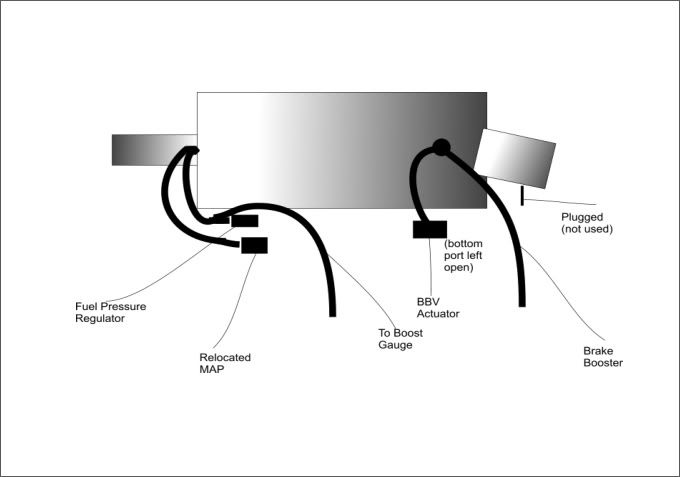
From under the supercharger nose I go into a Y that sends one half to the relocated MAP and the other gets another Y so my boost gauge up front and the fuel pressure regulator share that vacuum.
Then I rotated the large multi-plug fitting on top of the supercharger 180 degrees and off of it I run my brake booster and BBV. The top of the BBV actuator gets the vacuum line and the bottom port of the BBV gets nothing. It doesn't get capped off either. It's just wide open. The extra port on the large multi-port fitting that I rotated gets plugged off as well as the throttle body vacuum port.
The electronic BBV solenoid gets thrown in a box so I can send it to some poor guy over at ClubGP when his goes out.
IP: Logged
09:43 PM
JumpStart Member
Posts: 1412 From: Central Florida Registered: Sep 2006
I should be working on it some more in the morning getting this done and start sorting out the wiring.
More questions to come im sure.
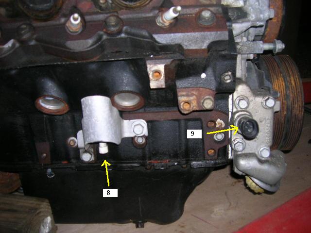
EDIT: This morning I moved the MAP sensor and removed the solenoid. Looks a little cleaner. I noticed that there is another plug(white with a yellow boot) that plugs in underneath the thermostat that is the same kind of plug as the one in the 7th picture(black with a yellow boot) just a different color. maybe that might help identify the black/yellow plug in the 7th pic. Again, Thanks for all the help everyone. Steve
[This message has been edited by JumpStart (edited 12-10-2008).]
IP: Logged
10:31 PM
Dec 10th, 2008
JumpStart Member
Posts: 1412 From: Central Florida Registered: Sep 2006
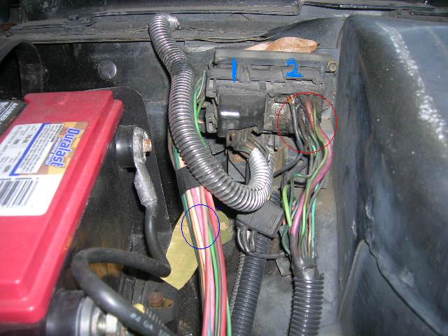
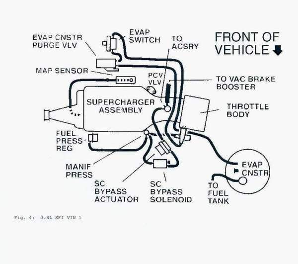
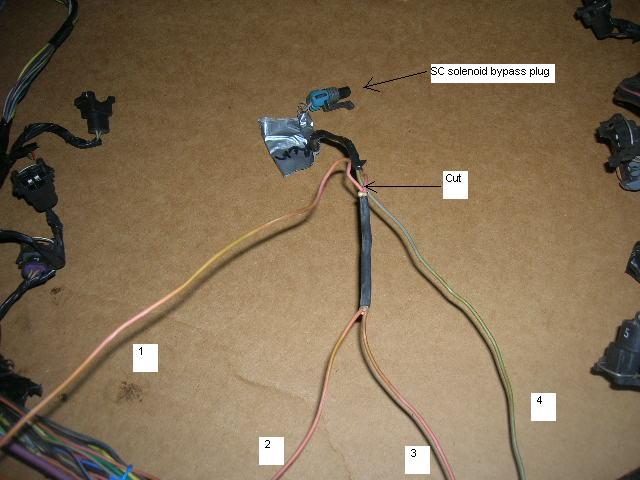
I am removing the SC solenoid bypass plug. This is what I noticed about the wiring. 1. seems to go to the injector plugs 2. runs to the O2 sensor 3. loose (back to the PCM) 4. loose (back to the PCM)
Im guessing that I only need to cut the peach colored wire where noted and remove the plug and the green wire (4) leaving (3) in the harness for the O2 and injectors?
Thanks , Steve
Steve I would tear that harness down until every piece of loom and tape is off of it. You want each individual wire separated. Those pink wires are 12 volts to the injectors and some other sensors need 12 volts as well. Then you start on the backside of that motor say at the knock sensor (or VSS actually) and run your single wire (start building your harness) until you get to the oil pressure sender (or switch whatever you use), then you cable tie your knock sensor wire to your oil pressure wire and then you start heading up the motor putting a cable tie (and clipping it clean) every couple inches or so. Then keep adding wires to your harness as you go along until you are at the back of your motor. Then you take off the whole new harness (it will hold it's new shape) and you tape it up solid and clean up all that old greasy loom in the kitchen sink and put it back on your new taped harness and tape it up as well. Of course on the loose end of your wires you have them marked what they are and what pin they go to on the PCM connectors. You also remove every pin from those connectors because you will be soldering and shrink-wrapping them back to the originals at their perfect length. You can mount your new PCM in the same location as your old one.
Here's the magic bullet right here. You send that PCM to Ryan (Darth Fiero) at www.gmtuners.com He will reflash it to a 99GTP PCM and get it back to you fast. You then wire it using the diagram you find here: Wiring instructions for 3800 Series 2 SC engine swaps into a Fiero using OBD-2 PCMs - Pennock's Fiero Forum: https://www.fiero.nl/forum/Forum2/HTML/093879.html (Download that PDF file at the top of the page)
IP: Logged
02:57 PM
Dec 12th, 2008
JumpStart Member
Posts: 1412 From: Central Florida Registered: Sep 2006
Ok, I have torn down the harness and separated it. I will also need to get an ECM so I thought while I was at it, I could just get that ,the clear and blue plugs and the wires from the plugs as long as I can get.
What year/make car would be my best bet to get this from so I have the best ECM and plenty of wire?
Thanks, Steve
ECM=PCM
I would email Darth Fiero at sp1@gmtuners.com and ask him if he already has a PCM sitting there that he could send to you. You then download a form and tell him if you want any modifications to the programming. Things like: What temp thermostat are you using. What transmission are you running. What temp do you want your fan to come on. Are you deleting the EGR, BBV, EVAP. What top speed do you want set for. Do you want any speedometer calibration. Where do you want your rev limiter set at. Etc... These are all flags and perimeters in the .bin file of the PCM that can be modified. Having Darth Fiero re-flash your PCM means you can wire it exactly like the PDF instructions show. It also insures you don't drive around with a check engine light on all time. There is also automatic transmission codes that need to be altered. Oh and don't forget the VATS security system that most likely needs disabled.
If Ryan (AKA Darth Fiero) doesn't have a PCM in stock then I would try and grab a PCM from a 99 L67.
It looked to me like your wires coming off C1 and C2 were long enough to work with. (since your going to pull them all out of the connectors anyway, right?)
IP: Logged
06:21 PM
JumpStart Member
Posts: 1412 From: Central Florida Registered: Sep 2006
I can use these connectors I have but I was under the assumption that I would need extra wire,other than what I have, to make some of the connections long enough to reach where they need to go. If some of the cars had longer wires running from the 2 connectors, I was going to try to get and use them instead. I hadnt intended to remove all the wires from the plugs unless I had to.
I can use these connectors I have but I was under the assumption that I would need extra wire,other than what I have, to make some of the connections long enough to reach where they need to go. If some of the cars had longer wires running from the 2 connectors, I was going to try to get and use them instead. I hadnt intended to remove all the wires from the plugs unless I had to.
Hope that made sense.
Steve
Well unless when they cut the harness they cut it in two different places (i.e. removed wire) I'm fairly certain you will have way plenty enough length to get to the console where your current Fiero ECM is mounted. Most wires I had 3 to 4 feet extra and that was using a '99 Regal harness. It seems like a lot of work to re-pin those connectors but it's not. You just clip the cable ties and then use some sidecutters/needlenose to cut/pry the retainers off of the screws. Then take off the covers and use a pick to gently remove the plastic clear and blue covers. Then use your pick or jewelers screwdriver to press the release on each wire. On the back of the connectors each pin slot is labeled clearly with it's pin number. Then you can build your harness and just run the wires wild where they go into the firewall. Say your harness is taped and loomed and complete from the firewall to the motor, then when you install the motor you shove that mess of wires through the firewall and cut each one to length to solder it to your same color pin wire (of course all those wires are tagged where they go, I found blue painters tape folded over was the easiest). Sounds like alot of work but it's not. Your going to have a bunch of pins in those connectors you aren't going to use like tranny wires and such. And then there are a few wire pin locations you will need to change from a Regal harness to a '99 GTP harness.
But you know what? Unless you are wiring exactly to the PDF Wiring Diagram that Darth Fiero wrote that I linked to earlier and if you aren't re-flashing your PCM to a code that can use that wiring diagram... I need to stop giving you wiring advice until you decide if you are going that route. Otherwise I'm just going to mess you up.
Take a measurement of how far the wires need to go to reach the PCM connectors and assemble the harness on the engine including the PCM connector to save a lot of time and trouble assembling the connector inside the car where you have less room and can not see the rest of the harness. Also use a good multi meter to check each wire when assembling the PCM connector to make sure there is no breaks in the wires. The list being refered to is just the pin out for one year of GTP PCM but the 98 to 2000 GTP PCM's will interchange so there is no problem following it if you can not easily read the wiring diagrams. Dan
Take a measurement of how far the wires need to go to reach the PCM connectors and assemble the harness on the engine including the PCM connector to save a lot of time and trouble assembling the connector inside the car where you have less room and can not see the rest of the harness. Also use a good multi meter to check each wire when assembling the PCM connector to make sure there is no breaks in the wires. The list being refered to is just the pin out for one year of GTP PCM but the 98 to 2000 GTP PCM's will interchange so there is no problem following it if you can not easily read the wiring diagrams. Dan
This is the way I am doing it right now. as I get more of it done, I will have a better idea if they are going to reach. Right now they just look a tad short.
quote
Originally posted by Bubbajuju:
FYI.
FIEROFLYER makes and sells some of the cleanest complete wiring harnesses in the 3800 Fiero swap world.
I have no doubt of that but right now I am doing good to just afford the parts otherwise I would because I have to have this car running and dependable by Feb because my daughter will need the car I am using now.
Originally posted by JumpStart: I have no doubt of that but right now I am doing good to just afford the parts otherwise I would because I have to have this car running and dependable by Feb because my daughter will need the car I am using now.
Right on, It wasn't so much of a plug for FIEROFLYER but more of a pointer that he's been doing these swaps for a long time and won't steer you wrong. Godspeed with it, Steve. It looks like it's going well.
What I do is get badly damaged harnesses off 3100 or 3400 engines from the wreckers usually for free or real cheap and use the wires from that harness to lengthen the ones needed on the harness you are building. That way you have the same colours and gauge of wire as the 3800 harness you are building. Just take your time and go one wire at a time and make sure your connections are soldered nicely and use heat shrink on every soldered connection and you will be fine. Dan
IP: Logged
12:33 PM
darkhorizon Member
Posts: 12279 From: Flint Michigan Registered: Jan 2006
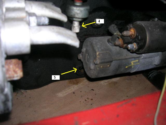
I have figured out that 4 and 8 are knock sensors.
Im guessing that 5 is the "engine oil level switch input" (brown and black wires) which is deleted. There are two of these exact same plugs in the harness. The other has grey and yellow wires (from what I can tell) Most of my wires are faded and are hard to tell the colors.
The only thing I can think this extra plug would be is the "change oil lamp control" but I dont see a reason for a plug-in for this unless it plugs into the tranny because it goes by mileage. If that is what it is then it is also deleted.