One of the plugs could be for the power steering rack pressure sensor that the Fiero also does not need. The easiest way to sort things out is measure with a meter from the connector back to the PCM and find the right pin then check with your wiring diagrams to see what it is for. Dan
IP: Logged
02:25 PM
Dec 18th, 2008
JumpStart Member
Posts: 1412 From: Central Florida Registered: Sep 2006
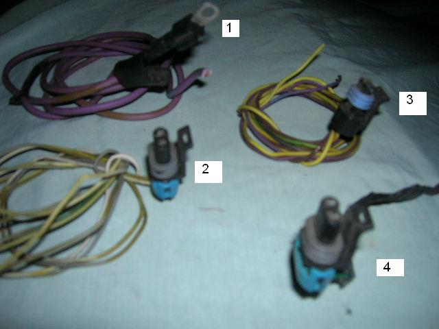
Ok...its been a while but I had to put this on the back burner for a bit but have made alot of needed progress on the engine and transmission. I am about to finish up the harness but still have 3 plugs Im not sure about and when I got the harness, it was cut loose from the plugs and with duplicate color wires, Im not sure which was which.
1. ? no idea but im sure its something stupidly simple.
2. and 3. I believe are for the Auto tranny that I am not using. They both have 2 wires each but some are faded or maybe from another year than Ryans pin-out so the colors dont match up.
4. Maybe the Auto tranny also and with only 2 wires,a green w/black and a (pinkish) one that runs to the O2 sensor in the exhaust manifold.
Now that I think about it, one of these might go to the evap canister on the donor?
EDIT sorry for the blurry pic I forgot to add lol Thanks for any help...again.
Steve
[This message has been edited by JumpStart (edited 03-12-2009).]
IP: Logged
07:51 PM
Mar 13th, 2009
JumpStart Member
Posts: 1412 From: Central Florida Registered: Sep 2006
if you cant find something to plug those random plugs into, then you dont need them obviously enough....
The purple wire should run to your starter in some fashion. I imagine you should run it to the range selector on the transmission, which is a purple wire that same size on the "big" connector. The starter "command" wire runs from the c500 to the range switch via the yellow wire.
IP: Logged
02:01 AM
Mar 21st, 2009
JumpStart Member
Posts: 1412 From: Central Florida Registered: Sep 2006
I have yet to remove the harness from the Fiero ( too dang old to be pushing the car around unneccarily )so some of this may be self explainatory after I do, but on Ryans pin-out, some of the wires from the Blue and Clear plugs run to either the C500,C203 or the ICM. Are they "spliced in" (leaving the wires already there) or do they "replace" wires that are removed?
Thanks, Steve
IP: Logged
04:33 PM
JumpStart Member
Posts: 1412 From: Central Florida Registered: Sep 2006
ok...I have the ICM figured out except for 1 wire. It is (A) on the ICM plug and becomes (E) at a junction plug. The wire is white (ish) and the only white wire listed is pin 54 (blue) ignition control to pin (A) of the ICM.
Any ideas on this white wire from the ICM pin (A) ?
Edit: I found where it goes. Forgot to look at the last page with the wiring to the 203 and 500. I did find the last wire (hopefully) that I am not sure of. The water tempature sending unit under the Thermostat housing has 3 wires. Yellow , Black and dark Green. I see no place to use the Green wire on the pin-outs.
Thanks, Steve
[This message has been edited by JumpStart (edited 03-21-2009).]
I did find the last wire (hopefully) that I am not sure of. The water tempature sending unit under the Thermostat housing has 3 wires. Yellow , Black and dark Green. I see no place to use the Green wire on the pin-outs.
Steve the green wire should run to C500 C2 (Dark Green/White). This is the feed to your temp gauge. (the pcm just fires the temp warning light)
The 3 wire plug to the thermostat housing should be connected to another 3 wire flat plug that runs to your wiring harness. There will either be a green wire that goes nowhere or be 2 wires instead of three. The 2 wires that should remain regaurdless are yellow and black, both going to your PCM. The green wire is spliced in the C500 for your temperature gauge feed. I forget exactly which wire on the C500 it is but if you have the pinout, you should be able to find it.
IP: Logged
03:19 AM
JumpStart Member
Posts: 1412 From: Central Florida Registered: Sep 2006
Ok...the only dark green wire I can find on the pin-out is #75 Blue which is the "Engine Hot Warning Lamp control" that runs to the D3 pin of the C500.
Does this mean that I need to splice these 3 locations together?
1. Blue connector pin #75 (ECM) 2. Pin D3 of the C500 (Fiero) 3. The green wire from the Coolant Tempature sending unit (3800 under the thermostat housing)
Part of the confusion on this is that the harness was cut up a bit due to removing it from the donor car I believe. Would have been alot easier if it were all in one piece.
Does this mean that I need to splice these 3 locations together?
No.
Blue 75 connects to C500 pin D3. This is the PCM telling the idiot light (temperature) on your dash to come on if your coolant is too hot.
The green wire on your coolant temp sensor (below your thermostat housing) gets wired to C500 pin C2. This is the CTS telling the temp gauge needle on your dash to move hotter or cooler.
[This message has been edited by Bubbajuju (edited 03-22-2009).]
IP: Logged
01:07 PM
PFF
System Bot
JumpStart Member
Posts: 1412 From: Central Florida Registered: Sep 2006
Originally posted by JumpStart: Thanks, I will wire the green up this way but I dont understand why I cant see it on Ryans pin-out?
It's not there. I emailed him when I was wiring my temp sensor and he helped me get it right. (I was confused because my harness dead-ended the green wire an inch after the connector, so I had to add wire to run it to C500)
quote
Originally posted by JumpStart: One other thing...What is "HO2S Sensor 1 heater" on the pin-out? One is a ground and the other goes to pin K of the C203.
Steve I'm not sure but I think the "H" stands for "Heated" hence Heated Oxygen Sensor 1 (pre-cat) The 02 Sensor should have four wires: Signal Low, Signal High, Ground and 12volts (which is the wire going to pin K, this allows it to pre-heat)
[This message has been edited by Bubbajuju (edited 03-22-2009).]
IP: Logged
03:48 PM
JumpStart Member
Posts: 1412 From: Central Florida Registered: Sep 2006
Thanks once again and just gave you a Big plus. I now seem to have all the wires from the ECM to the engine wired up,and to the C500 and the C203 sorted out.
I now have a few wires from the ECM (about 9) left. Im thinking that I cant use some of them anyway but best to be sure.
They refer to... High speed fan control [blue 5] Intake air temp sensor (in the boot just before the TB?) [blue 17] Vehicle Speed sensor (transmission?) [blue 64 and 65] Trans gear selector position switch [blue 68 / clear 18 and 56] OBD2 datalink conector (no idea unless its the ALDL from the donor which I dont have) [blue 15 and 59]
After this I should be able to wrap up the harness.
They refer to... High speed fan control [blue 5] Intake air temp sensor (in the boot just before the TB?) [blue 17] Vehicle Speed sensor (transmission?) [blue 64 and 65] Trans gear selector position switch [blue 68 / clear 18 and 56] OBD2 datalink conector (no idea unless its the ALDL from the donor which I dont have) [blue 15 and 59]
High speed fan control just gets deleted. Intake air temp sensor needs to be connected. Also wire it's ground which goes to PCM Blue 17. Trans gear selector and all tranny wires (except vehicle speed sensor) get deleted
Then head to the junkyard and grab a OBD2 datalink connector off of any say 1998-2002 GM car. (its the blue computer interface connector usually found under the dash on the drivers side) Wire the two PCM wires to it and then it needs grounds wired at pin 4 and 5 (of the connector) and constant 12 volts at pin 16 (of the connector) I think I grabbed the power off of my cig lighter. And then I just have my OBD2 connector stored behind the cig lighter plate on the center console.
Now on the Vehicle Speed Sensor I can't help you much. I don't have any experience with a 92 transmission so I don't know how it is wired. Also I don't know the pulse width it is going to put out. All I can tell you is that your PCM needs to be connected to it (high and low signal). What I did with my wiring was just splice my PCM wires into my Transmission VSS. That way the PCM got it's feed and my speedometer got its feed.
Well this has given me a headstart and 4 more wires to lose. I will check on this Mon afternoon and I am assuming that the OBD2 data link is the same thing as what is in the Fiero console to check for codes? (jumper A and B) ?
Originally posted by JumpStart: ...I am assuming that the OBD2 data link is the same thing as what is in the Fiero console to check for codes? (jumper A and B) ?
It is. It's just a different connector with a different pinout. You need it to run cool scan gauges and diagnostic software. Also if you have a check engine light you can take it up to autozone (or whatever parts chain is near you) and get it scanned for trouble codes for free.
IP: Logged
07:51 PM
Apr 5th, 2009
JumpStart Member
Posts: 1412 From: Central Florida Registered: Sep 2006
Ok...I now have the exhaust manifold to replace the cracked one and the rubber tubing with the intake air tempature that fits on the throttle body. Its getting closer.
I remember seeing in a thread that someone had found radiator hoses and had posted the part number that would fit in place with some shortening of one or both of the hoses but I cant find it. Anyone know the make/model or part # of the radiator hoses that would fit?
I remember seeing in a thread that someone had found radiator hoses and had posted the part number that would fit in place with some shortening of one or both of the hoses but I cant find it. Anyone know the make/model or part # of the radiator hoses that would fit?
Thanks, Steve
I can't find that thread off hand but I went with Autozone L-251 and XL-1023. The passenger side I trimmed an inch off at the motor but shouldn't have. It was better left alone. The driver's side is a little fat so I used multiple clamps to attach it top and bottom. The setup has worked great and the hoses fit like they belong as far as the length and bends.
IP: Logged
01:49 PM
JumpStart Member
Posts: 1412 From: Central Florida Registered: Sep 2006
I have now found that the only wire on the pin-out for the Alternator is 61 clear that goes to B or L of the Alternator. 61 Clear is a red wire and im sure it goes to the red wire on the Alt. but what about the other two wires ( blueish/greenish) comming from the Alt.? Where do they go?
Also I noticed that my 2 oil sending unit wires (tan/black and black/white) have nowhere to go. Help??? I must be missing something here. Thanks, Steve
[This message has been edited by JumpStart (edited 04-13-2009).]
IP: Logged
07:04 PM
PFF
System Bot
darkhorizon Member
Posts: 12279 From: Flint Michigan Registered: Jan 2006
Also I noticed that my 2 oil sending unit wires (tan/black and black/white) have nowhere to go. Help??? I must be missing something here. Thanks, Steve
Tan/Blk goes to the fuel pump relay, Blk/Wht is Chassis ground
IP: Logged
07:36 PM
Mike Gonzalez Member
Posts: 5093 From: Colorado Springs, CO. USA Registered: Jul 2001
I have now found that the only wire on the pin-out for the Alternator is 61 clear that goes to B or L of the Alternator. 61 Clear is a red wire and im sure it goes to the red wire on the Alt. but what about the other two wires ( blueish/greenish) comming from the Alt.? Where do they go?
Off the top of my head, one goes to your Batt light on the dash (alt wont work without it) and one gets +12V, been a while, but I can go get my notes later if you dont get it figured out. PM me if I can be more help.
IP: Logged
07:40 PM
Apr 14th, 2009
JumpStart Member
Posts: 1412 From: Central Florida Registered: Sep 2006
Why would you wire the oil sending unit directly to the fuel pump relay? lol
Steve
The oil sender work as a backup to your FP relay. If the fuel pump relay goes bad it will still run the fuel pump when there is oil pressure. You dont need to run it, but it is the way the Fiero is originally wired.
I have now found that the only wire on the pin-out for the Alternator is 61 clear that goes to B or L of the Alternator. 61 Clear is a red wire and im sure it goes to the red wire on the Alt. but what about the other two wires ( blueish/greenish) coming from the Alt.? Where do they go?
Also I noticed that my 2 oil sending unit wires (tan/black and black/white) have nowhere to go. Help??? I must be missing something here. Thanks, Steve
Steve did you figure it out? On the alt you only need the large red wire and the small red wire. The other two you can dead end somewhere because you don't need them in this application. Then the PCM lights up the alt light by connecting C203 (B3-should be a brown wire) to PCM Blue 36. The gauge just reads off the 12 volts it gets from anywhere.
As far as the oil pressure... I gutted out my gt gauges (center console) and turned that area into a three gauge system. I made it- oil pressure, boost psi and voltage. (all cheap Sun aftermarket gauges) Off of my oil pressure nipple on the block I added a tee. I then used the stock 3800 oil pressure sensor to ground an idiot light (which I don't have connected but could use the "shift light" or whatever for this app. Then on the other side of the tee I used a cheap Sun pressure sender that wires to my cheap Sun oil pressure gauge. It is my understanding that if you use an '88 Fiero oil pressure gauge then it grounds your idiot light and also sends a resistance signal to your gauge. I think the '88 is recommended only because of it's better design. Anyhow if you want to go with the '88 Fiero sending unit to use the stock oil pressure gauge and idiot light then the wiring should be in your service manual. By now you probably have it figured out, but hey...
(P.S. I only went with the Cheap Sun unit because the sender and gauge was half the price of a replacement Fiero sender and my old Fiero sender and gauge always gave me trouble.)
[This message has been edited by Bubbajuju (edited 04-18-2009).]