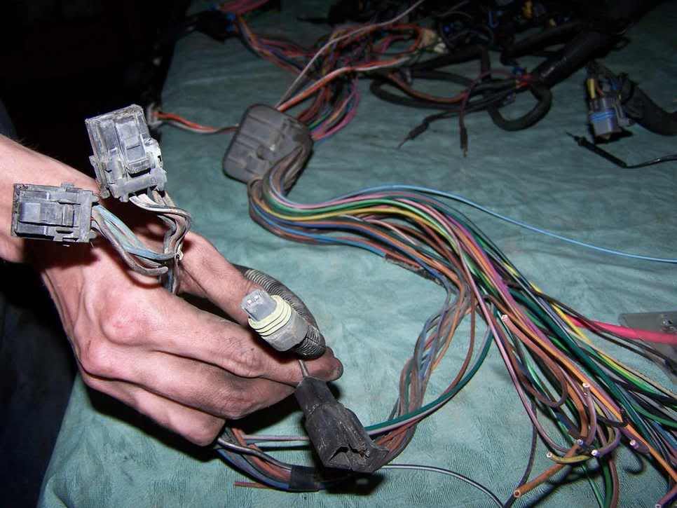
I am pretty sure that I will just run all the wires I need straight from the connector, but I figured that before I cut all these nice connectors off, I would see if anyone knew where I could extract some usefull stuff, as I hate to cut out nice connectors such as these. I also dont want to have globs of wires just laying around, but I think i will either way. Basicly this is just a picture tour of a harness, and a converfermation on my wiring project.
This is the connector for the stock relays, the other 2 connectors here that are meaningless I suppose.
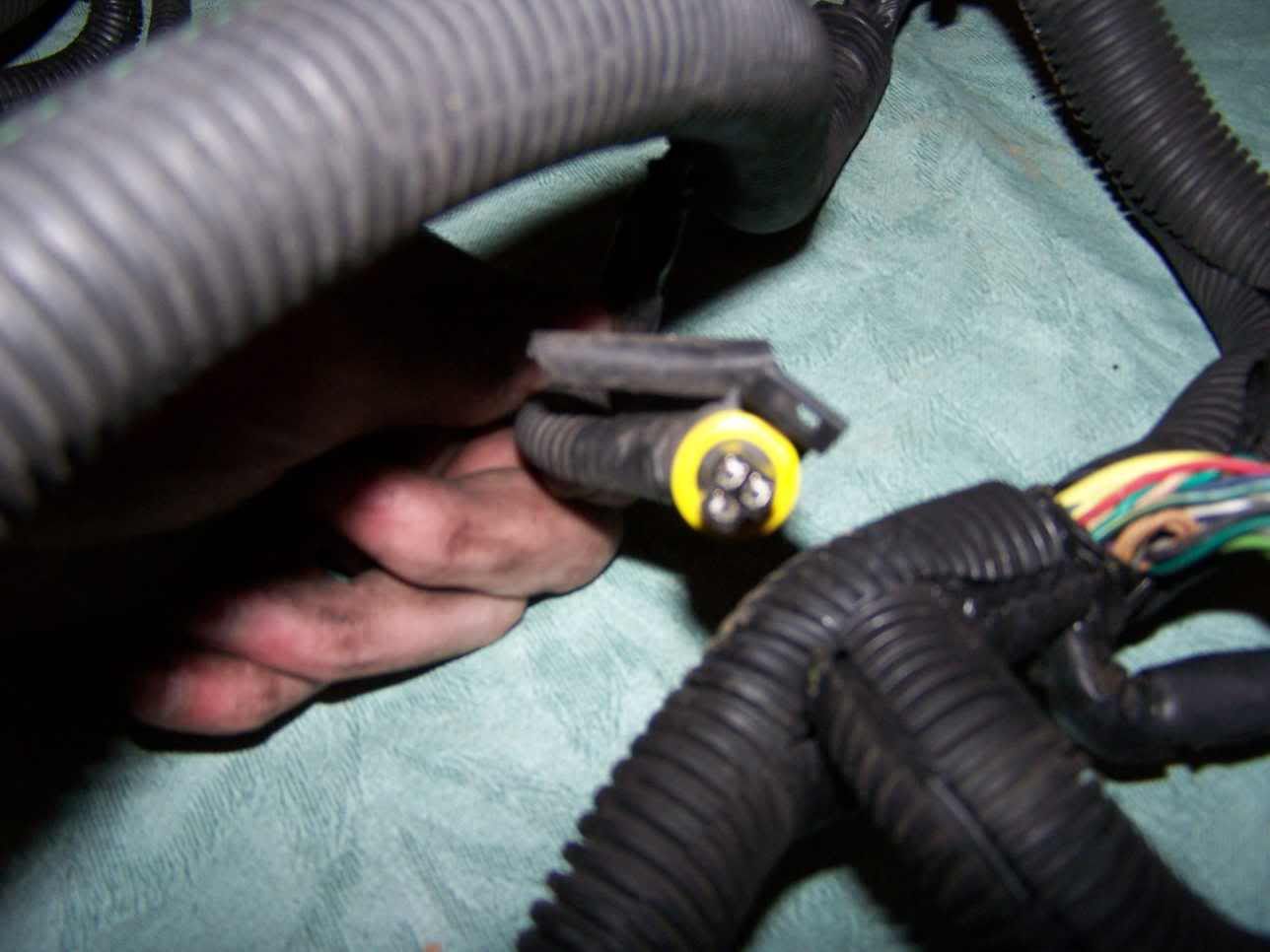
some yellow colored plug hanging out of one of the hareness looms, cant seem to find a home for it.
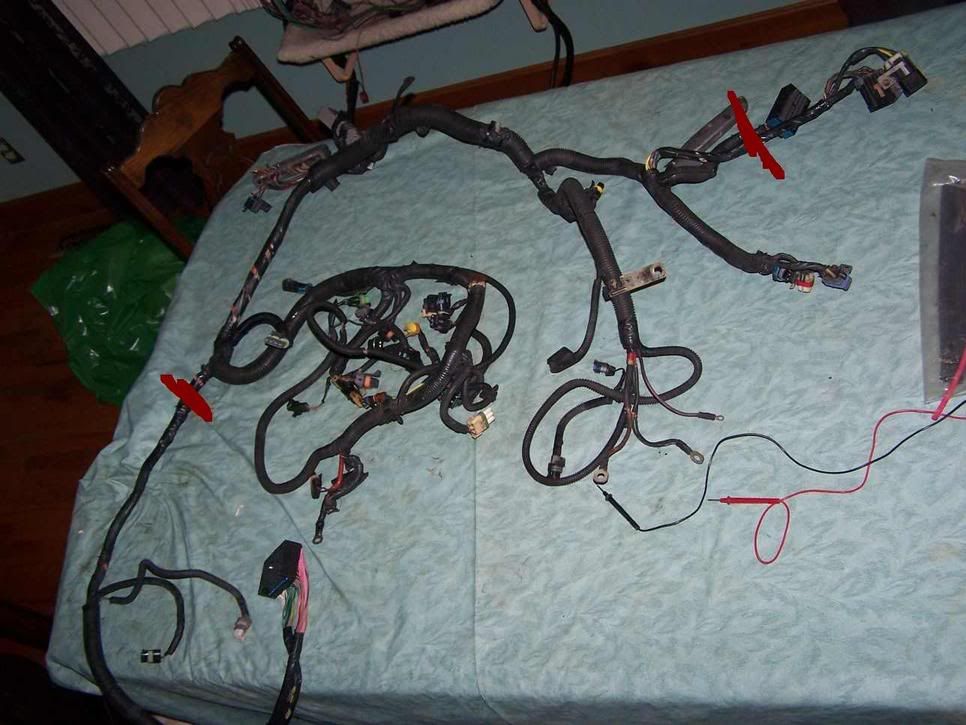
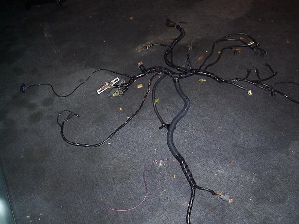
Picture showing where I want to cut the harness, asuming I cant use it otherwise.
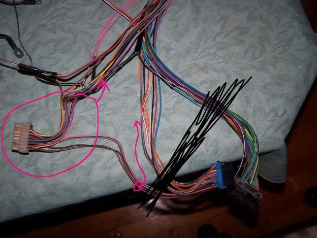
These are the connectors I had in question, seems to be alot of familiar colors in these.
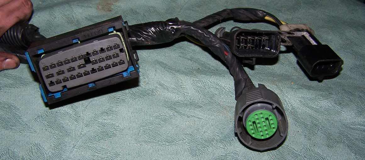
Here is the c203 connector off the donor harness, black lines show where I want to cut, and the red area is the usefull stuff I guess.
Just looking for comments or anyone that has done this before for now, I will add in my stuff as I do this little project tommorow.
------------------ Check out my 3800 swap thread and lend your advice!
The one your holding looks like the MAT , the one right below that looks like the fuel tank line connector, allthough its missing 2 of the 3 wires. The ones in question pics: the green 1/2 ballish looking dealie won`t be used, but sometimes left in the harness. I`m not sure of what years you took them from, so I don`t want to confuse you more --or me for that matter ..or have you make a mistake on my part--I have a pretty good idea what they are--at the minute have no way to look for you. I will try to see what I can come up with---did you keep the fuse block (under hood)--not box from 3800? Hopefully one of the gurus that do this on a daily basis will chime in...
IP: Logged
10:19 AM
86GT3.4DOHC Member
Posts: 10007 From: Marion Ohio Registered: Apr 2004
I am pretty sure that I will just run all the wires I need straight from the connector, but I figured that before I cut all these nice connectors off, I would see if anyone knew where I could extract some usefull stuff, as I hate to cut out nice connectors such as these. I also dont want to have globs of wires just laying around, but I think i will either way. Basicly this is just a picture tour of a harness, and a converfermation on my wiring project.
This is the connector for the stock relays, the other 2 connectors here that are meaningless I suppose.
Those are the fuel pump and AC relays, the 2 wire connector is the IAT sensor, the one wire is a fuel pump bypass input, if you were to apply 12v to it in the car it would turn on the fuel pump.
quote
some yellow colored plug hanging out of one of the hareness looms, cant seem to find a home for it.
No idea, the only thing that Ive seen remotely simular to it is the CTS by the throttle body, if you've got that I would loose this one.
quote
Picture showing where I want to cut the harness, asuming I cant use it otherwise.
I would not cut ANYTHING, that was how I did it, fully dissassemble the harness and then when you can see everything, most of it will just pull out, and anything that does need cut you can cut with the most possible wire to use. Otherwise later you are going to get into the harness and get confused by all those wires that go nowhere.
quote
These are the connectors I had in question, seems to be alot of familiar colors in these.
Well, the 3 prong im assuming is just a ground connection, and the middle yellow wire feeds to the starter solenoid circut, it goes to the tranny switch The 10 prong rectangle I think has something to do with the fuel tank, I havent gotten into it yet The big square I have no idea, but Id guess maybe ABS?? The round green one is keyed the same as the tranny connector and will actualy plug into the tranny even though it doesnt belong there, again I have no idea. I removed all those connectors
quote
Here is the c203 connector off the donor harness, black lines show where I want to cut, and the red area is the usefull stuff I guess.
Just looking for comments or anyone that has done this before for now, I will add in my stuff as I do this little project tommorow.
All you really need from the Fiero harness is the C203 and C500 connectors, I would cut them with as long of wires on them as possible, the less splicing the better. I am actualy eliminating the C500 from the new harness, I will put all the connections under the glove box, it will clean things up and make for fewer splices
------------------ If its not broke, you're not driving it hard enough. GO OR BLOW.
My car seems to prefer the latter, 6 engines, 2 trannys, 1 driveshaft and a whole lotta fun :D
IP: Logged
11:36 AM
darkhorizon Member
Posts: 12279 From: Flint Michigan Registered: Jan 2006
well, I have been stripping the harness down today, I found alot of useless wires I guess, but I really need to get them tracked down on the diagrams
Some mystery wires have been found running from the starter area to the big square connector, along with a few random plugs that go to nothing, so I am mostlikely going to pull that plug out. I figured if I hook everything I can up, I will just cut anything else, and pull it out . There are alot of wires running to my old fuse holder.
I also asume that the alternator charge wire hooks to the starter?
IP: Logged
05:58 PM
Jun 29th, 2006
86GT3.4DOHC Member
Posts: 10007 From: Marion Ohio Registered: Apr 2004
Step1: Remove ALL of the tape, loom, and attatchments
Step2: Dissasemble the back of the junction/fuse block and remove the plugs, toss the block aside. Now there should be some blue plastic strips on the sides of the plugs, you will want to slide those out, as they secure the wires into the plugs. Then pull all the wires out, pay no attention to where they go. Do not cut anything yet. You will notice that many of the individual plugs have 2 wires going into them, you do not want to cut those yet unless you have to. What you will run into if you do is you will be wiring the harness, and come to this cut wire and ask yourself "was this supposed to plug into the ECM or the block?" because you never know what might have been cut improperly in the past. You will have to cut some of the pairs to untangle them though.'
Step3: Remove all the crap that pluged into the block that does not go anywhere now. Dont cut stuff, you might need long lengths of whatever color wire in the future, so save it.
Step4: Remove all the wires from the PCM connectors. Now I did not label these in any way, its pretty easy to get them back in right. You will want to start by removing the plasctic covers from the back of the plugs so you can see where the wires go in. then you will need to cut or remove the washer from the front of the through bolt, it holds the halves together. Then, slip the clips in the back of the metal that hold the plastic front on and remove it. You will then need to poke in the cracks on the sides of each nose cover (the blue and clear pieces) and pop them off, DO NOT loose or damage them, they actualy hold the wires in place. Then start pulling wires out, you will need a knife to slightly pull the little plastic fingers back while pushing the metal plug away from the center and down. Pull all the wires out.
Step5: Go to the store and buy 3 rolls of electrical tape and 200 small wire ties (I bought 100 and ran out) as well as some tags, I had some from building the house with little strings and tag faces for construction wire labeling. You could use tape if you had to. You will also need about 5' of heat shrink tubing about 3/32nd ID, a soildering iron or gun, and soilder, a little soilder assistant with two alligator clips on a mount to hold the wires helps, also some masking tape and a sharpie.
Step6: remove each sensor/etc plug from the giant mess one at a time. Coil its wire and wire tie it into a bundle, label it using the PCM pinouts, matching the wire colors to the use. Many wire colors are repeated, so be carful in the future. You will run into some 2 to 1 plugs from the junction block, you will need to cut these now, you might want to label some of them, but all pinks are 12v, and thats what most of them are so you should be okay.
Step7: Sort through the plugs you dont know what they are. Most of them just fall out of the harness, I think I had one light green wire go from the tranny gear selector switch to that wierd 2x3 grey square block. After exausting options, I just cut it and worked it into the harness in case it was important later. Most of the others you will find go to cut off wires that someone sliced in engine removal, Im assuming we wont be needing any of those. Set those plugs aside, but dont loose them in case we need them later. You will have at least one 2x3 grey plug, a round plug all but identical to the tranny's connector, a black rectangle I think 8 or 10 pin plug. All those aernt used.
Step8: Once you have all the important plugs and unused plugs removed you will find several wires that dont go to plugs, but instead ran from the PCM to the jucntion block, those are mostly sensor outputs or PCM feeds, coil them all together and set them aside. You will also have a couple of odd balls like the alternator wire, I suggest bundling and labeling it too, as well as the rest. If you keep everything bundled it will be much neater and easier to work with. Labeling everything helps because even if you know what something is now, day after tomorrow you dont want to have to look it back up after staring at miles of wires for hours on end.
Step9: Now I guess unless I forgot something this is where we start building the harness. I picked the easy stuff first, the rear injectors. Start by plugging them in, then cut the first wire tie, then run it to the next injector, wire tie the wires together to hold shape, then cut the second injectors tie and run both to the next and tie, then cut the last injectors wires loose, and run them to the front of the engine tying every 6 or 12". The firewall passthrough is very near the front engine lift point, so I tied all wires to this. Then add another section of plugs, EGR, Evap, MAP etc and repeat. Always tie to the closest wires, and tie a lot. tie as you run allong other tied wires, you will end up with 5 or 6 layers of tied wires tied to other tied wires, this is okay, keeps everything tight and neat. When you are done you can remove the harness from the engine and it will hold its shape if you tied enough. Then start at one end and wrap it tightly with tape, only cutting the ties as you come to them.
Step10: I reccomend running the 3 tranny connectors, and 02 on the left of the engine, then run all the others around the front of the engine, seemed to fit best this way. I wrapped the alternator wire right into the harness, and the main ground harness. I ran those two down over the AC compressor and ran them with the main battery wires to the battery area. I would not splice them in as redundancy is very good.
Step11: once you have a nice neat harness leading to a giant ball of mess where the PCM would be, you are in good shape. I would test fit the engine and make sure you're shortest wires are going to reach the PCM where you want it. Then take it all back off the engine, and take it inside.
Step12: From here I made 4 distint paths coming off the harness 1:wires not yet sorted 2:wires that dont go to the ECM 3:wires to clear plug 4:wires to blue plug I use twist ties to hold them as far up the harness as I could to keep them clean. you dont have to make them at first, just remember to sort as you come to them
Step 13: Begin sorting. Pick your shortest wires and do them first, you will need a continuty tester and a jumper wire with alligator clips. Clip to the first wire and look up its color in the PCM output. When you find what its supposed to be, test continuty to this plug. Remeber many wire colors are repeated. Once you figure it out see what connector and pin it goes to
Step 14: prepping the PCM connectors for use. The black holey pieces need to be inserted from the front of the PCM connectors, inside the shell. Then take your white pieces and put the gubber gaskets back in, make sure you put the right one in the right connector, as you can use them for error checking later, obviously you shouldnt put a wire in a hole that wasnt used before. Do not put the clear or blue caps on yet, the wires wont go in with them on. Also dont clip the white piece into the metal shell, you cant force the wires in like that, leave a couple of inches space. As you are inserting the wires make sure you do not cross other inserted wires, you dont want a tangle in the connector. The backs of the metal shells are numbered so it should be easy.
Repeat step 13, sorting out wires that dont go to the PCM as you go. I reccomend not tying the engine and tranny harnesses together at first, as that will make determining which pin it goes in much easier, then once you do all the engine ones, put the tranny side on.
Step15: after you have ALL of the wires in place and the 2 connectors seperated clear back the the harness split. Go through one by one cutting out the longest, slip on some heat shrink tubing, soilder the ends back to gether and heat shirnk. I did not cut down every single wire, just the really long ones.
Notes: There are 4 odd,really long, wires on the tranny connector, white, yellow, black/wht, grey. They have both PCM pins and jucntion block plugs, Id just cut them down and soilder on the PCM connectors. These are not shown in the 01 schematics, only the PCM pinout, I believe they are refered to as transmission range switch (a,b,c,p).
Also the 00 GTP L67 seemed to have more informative schematics in it.
IP: Logged
10:48 AM
darkhorizon Member
Posts: 12279 From: Flint Michigan Registered: Jan 2006
I really want to break down those PCM connectors? wouldnt it be easier to just remove the ones I dont need, then strip the rest of the harness out? I dont really need to lengthen much for anything, I sorta was planning on not even unwraping most of the engien side stuff it it was possible.
I suppose I should just do it this way, as it is the right way of doing it, because I can set all my lengths right, right to where I want the pcm. I will be working on the car all day today, and I am running out of things to do untill this is the only thing left to do.
IP: Logged
12:38 PM
86GT3.4DOHC Member
Posts: 10007 From: Marion Ohio Registered: Apr 2004
Its really easy, I didnt do it on my 3.4DOHC because I thought it would be too complicated, and now I wish I had. I guess if the stock PCM connections will reach where you want them, and you're okay with how the harness looks, you dont have to, but this car is going to be my reliable daily driver, so I didnt want an overlooked wire coming back to bite me later. I think with as many wires as you have to remove it would be worth your while. One thing though, keep all your cuts and splices in one place, all mine are within 8" of the ECM, that way they are shielded from the weather (going under console) and most importantly, if something goes wrong I dont have to go searching through the harness for a bad splice.
(plus im trying to slow you down so I can be done first )
j/k
What did you do for the coolant feed? im working with an 87 so I dont have a return, just a feed. If you can wait until later today, im working on a pin by pin diagram for the C203, C500, and FP/AC relays. Should be done pretty soon, im sorting out the reverse lights and that should be about it.
------------------ If its not broke, you're not driving it hard enough. GO OR BLOW.
My car seems to prefer the latter, 6 engines, 2 trannys, 1 driveshaft and a whole lotta fun :D
IP: Logged
01:55 PM
86GT3.4DOHC Member
Posts: 10007 From: Marion Ohio Registered: Apr 2004
OO my coolant is totally figured out, just not done as I have to bite the bulllet and drill and tap.
Anyway, its really simple, the driver hose goes onto the big thermostat housing, and the bigger pass side hose goes onto the big inlet to the water pump. Then the little hose that reaches up front (at least thats where it is on my 88 4cyl), goes into the little hole coming out the side of the intake manifiold. The smaller inlet on the water pump gets pluged, I think they make a freeze plug that works well for this?
IP: Logged
08:20 PM
darkhorizon Member
Posts: 12279 From: Flint Michigan Registered: Jan 2006
BTW I sotra like the idea of putting the pcm in the intake area, and the wires seem to line up really nice. I would be way intimidated to unpin those 80 wire connectors, as i feel that would be suicidal to my project. I know it could be done, and I am capable of it, just not right now. As much as everyone regets hacking together the first time, I want to not devote alot of time to an area that I am totally not familiar with like this, as I think I will just redo it later when I do somthing interesting with the car.
IP: Logged
08:27 PM
86GT3.4DOHC Member
Posts: 10007 From: Marion Ohio Registered: Apr 2004
Uh, im pretty sure the hole on the WP is an OUTPUT, and the intake is the return, so you would not get flow through the heater core if you hooked into the intake one.
I took the elbow out of the tensioner/alternator bracket that was taken off the engine, and fabricated a little fork dealy to hold it from poping out, then a heater hose can just clamp right on it.
Do you have any part numbers on those radiator hoses?
IP: Logged
10:25 PM
PFF
System Bot
2002z28ssconv Member
Posts: 1436 From: Orlando, FL Registered: Jun 2005
Does anyone know of any sources to purchase the metal pins than terminate the wires inside of the connector? It seems like it would be better if we just put new ends on the wires instead of splicing them in the middle.
IP: Logged
08:51 AM
86fieroEarl Member
Posts: 2203 From: Orlando, FL Registered: Jun 2002
BTW I sotra like the idea of putting the pcm in the intake area, and the wires seem to line up really nice. I would be way intimidated to unpin those 80 wire connectors, as i feel that would be suicidal to my project. I know it could be done, and I am capable of it, just not right now. As much as everyone regets hacking together the first time, I want to not devote alot of time to an area that I am totally not familiar with like this, as I think I will just redo it later when I do somthing interesting with the car.
Like what 86GT3.4DOHC says, Your going to have to unwrap the wireharness to start out with, I cut the 3800 ECM connectors off and the sensors and started from scratch (Took forever that way and I will never do that again) I did it this way for a cleaner looking install. If you keep the harness as is some wires you might have to lengthen or shorten.
The wireharness has to be the most boring part of this swap yet, I had to pull my harness and redo it, My swap ran nice but soon as I hooked my obd 2 code reader to it, It had like 4 sensors miswired. Plus after all the times of ripping a certain area of loom out to fix a problem here or there the harness started looking bad and messy, So I pulled it and took it home.
Here is a pic of the finished harness, Im still going to use a themal wrap for the body of this harness The IMC harness can be left the way it is.
If I had to start over, I would buy a already built harness LOL, The 700bucks for done harnesses are well worth it.
When I get home tonight I will post some wireing info for the pinouts and what connectors go to the fiero connectors ect.
[This message has been edited by 86fieroEarl (edited 06-30-2006).]
IP: Logged
10:30 AM
Mickey_Moose Member
Posts: 7594 From: Edmonton, AB, Canada Registered: May 2001
Originally posted by 86fieroEarl: Your going to have to convert the speed to work with a 4ppm, Your going to need a 1k ohm resister and a 22k one.
...beat me to it, you only need the 1 wire to drive the Fiero speedo - the purple wire is actually connected to ground on the speedo PCB (hence it is not needed).
Tim
IP: Logged
10:53 AM
86GT3.4DOHC Member
Posts: 10007 From: Marion Ohio Registered: Apr 2004
Well here is what Ive come up with for the wiring, please dont yell at me if something is wrong, I have not tried it yet, but from cross refrencing probably 20 diffrent schematics, Ive come up with this. I spent a lot of time on it, and am not getting anything out of distributing it, so gimme a plus if its helpful.
I still have not figured out the trunk release saftey yet, as I cannot figure out how its wired in the Fiero, there only appears to be one wire going to the tranny, and its not like ground=enable, at least as far as I can tell. I will look into it later, and if nothing else I will just have to disable the saftey lockout on it. I also am not sure about the tempature sender for the guage. There is a dark green wire from the CTS that runs straight to the "instrument cluster", and there is already a wire for the temp warning light, so Im assuming it will feed a guage, though I have never seen it said specificaly in a diagram.
Also note I have decided to use the original upshift indicator for the change oil light (though I may go with the low oil indicator, dunno yet). I am also not sure about the AC yet, I think the Fiero sends 12v to signal on, and the L67 sends ground to the PCM to turn it on. I'll update when I figure this out.
Anything other than wire color thats highlighted is something im unsure of
****NOTE: I forgot the 12v feed for the tranny, itsa pink at location 5 of the round tranny connector, you will have to select a feed for it****
AND you may want to evaluate my distrubution of 12v(pink) feeds, to make sure im not over powerering one wire, but I think I distributed them evenly C203 Pin - Wire Color - Original use - New Use - Pin on conversion harness
C500 Pin - Wire Color - Original use - New Use - Pin on conversion harness
ALDL link, Fuel Pump Relay, and AC relay
L67 Tranny connector (not shown in any diagrams, only pieceing things together here - use at your own risk)
I am fairly positive Pin D must be grounded for the ECM to see the gear posistion, as the other four wire connector (the one that runs to the ECM) terminates to ground in the tranny, which is this black wire
[This message has been edited by 86GT3.4DOHC (edited 07-01-2006).]
IP: Logged
12:44 PM
2002z28ssconv Member
Posts: 1436 From: Orlando, FL Registered: Jun 2005
I checked with the dealership today. They do have the right wire terminations but they wanted to charge me $2.50 a piece for them. Sorry! :O They told me they were made by Packard. So I'll try to skip the middle man and let you know what I come up with.
IP: Logged
03:51 PM
Jul 1st, 2006
darkhorizon Member
Posts: 12279 From: Flint Michigan Registered: Jan 2006
Well, I think I am going to try the easy way out first. I will just pull all the wires from the harness I can without messing around with unpinning the pcm at all, then run my own wires from the pcm to my connections I need to make. I might be going a bit out of the way by adding wires to run to the connectors, but it will work, just might have some useless wires running around.
I am really just trying to figure out where I need to run constant power, and how to wire the alternator. I have it so it jumped so it will be constantly charging, do I just hook the power outlet straight to the battery? I asume that the big wire in the harness runs down from the stock alt location to the starter, where it piggy backs the starter feed from the battery? I know that there is the dual post distro block by the battery for my constant power connections there, but I sorta dont even know what to hook up to it other than 1 pcm wire?
I really want to emphisise that I dont care how things look under the hood, I just want things to work when I do it the first time. I would rather put a mostly stock harness in there and add some wires if I have to to get things hooked up, rather than build one from scratch right now. I dont plan on being ever done with this project, I really just want to take things slowly and make sure I have a good understanding of how it all works, then I can do more complicated things in the summers to come. My current plan is just to get all the needed connections to everything outlined in the fancy colored excel sheet, then clean the harness up a bit when I have it on my motor. I figure that if I just run the harness a fancy way, I can lengthen or shorten the length of most things I have to, but it should work as the PCM is going to virtualy be run in the identical place that it has allways been in when it was in the 98 gtp. I might even work it into the airbox for some high tech cooling action.
So I have one last question that I have been thinking about. I basicly want to know if I can pull EVERY wire that doesnt directly go to a internal splice or directly to the PCM out of the harness. The fusebox connector and the body connectors have alot of stuff that just runs to eachother, and a few that run to the tranny.
Also, the gtp's ran fuel pump resistors, that slowed the fuel pump down when cruiseing and stuff. Do people still use them in swaps? I have mine all ready here with the connectors, I suppose I will just wire them in.
And another thing, are any of these sensors stolen off of the motor that came out of the fiero, like the oil pressure, temp sensor. whatever I forgot sensor?
[This message has been edited by darkhorizon (edited 07-01-2006).]
IP: Logged
01:51 PM
darkhorizon Member
Posts: 12279 From: Flint Michigan Registered: Jan 2006
Just did some more research on the alternator. Can I wire the charge wire on my 2 wire alternator to the charge output of the PCM?
Kelly/Springfield: XL-1004
Goodyear: 62053
Napa: NBH 7620
Dayco: 71696
AC Delco: 26030X
Metric Interchange: 0096931
Those are for the pass side coolant hose. And I am positive that all we need is to tie into the intake manifold for our heatercore. The waterpump is basicly 2 inlets, one big and one small. It may apear at first to have an input and an output, but it isnt.
[This message has been edited by darkhorizon (edited 07-01-2006).]
IP: Logged
02:30 PM
Jul 3rd, 2006
86fieroEarl Member
Posts: 2203 From: Orlando, FL Registered: Jun 2002
If your fiero has a temp light then that connects from the D3 c 500 To the Temp lamp indicator on the EMC.
This is using the GTP 3 wire sendor, If your going to use the fiero you will have to do something about the temp pinout on the emc or else you will have a p0118 code.
Using the fuel pump I used the fieros Relays and used a fuel pump from a 89 3.8 turbo transam.
[This message has been edited by 86fieroEarl (edited 07-03-2006).]
IP: Logged
06:46 PM
PFF
System Bot
Jul 11th, 2006
darkhorizon Member
Posts: 12279 From: Flint Michigan Registered: Jan 2006
Well, I hacked off my body connectors today, and sorted all the wires coming out of the pcm into to 2 main bundles. One bundle went to the transmission side 4 body connectors, then the other bundle was the ones coming from the fuse box. I was left with 15+ pink wires coming out of the engine harness (which is still fully wrapped and untouched as I know that I wont be removing anything specific from this). What should I do with those pink wires? can I just juntion them and run them all to switched/constant 12v+? There seem to be alot more wires that went to the pcm than I thought there would be, about 25 or so, I am getting the pinouts now to go check on what these will do.
Then I pulled all the wires that had no homes on connectors I am using all the way back to the pcm, and have the sectioned off.
[This message has been edited by darkhorizon (edited 07-11-2006).]
IP: Logged
05:27 PM
Jul 12th, 2006
tampalinc Member
Posts: 776 From: Waukesha, WI Registered: May 2001
Huge thanks to everyone in this thread. I sent my harness to Loyde in Feb 2005 and am still waiting to get it back. I finally decided to purchase a spare harness and computer from Ed Morad on ClubGP. Tonight I stripped the wrap from the GP harness, pulled the pins from one of the PCM plugs, and coiled up the wires. Keep the details coming. At this rate my car will be running by this weekend and driving sometime next week.
[This message has been edited by tampalinc (edited 07-12-2006).]
IP: Logged
12:18 AM
darkhorizon Member
Posts: 12279 From: Flint Michigan Registered: Jan 2006
Well, I soldered together all the pink wires into 2 bundles, one bundle with the maf and 3 injectors (2,4,6), and another bundle with 9 unidentified engine harness wires, and the other 3 injectors. I asume most of these are useless so do avoid screwups later I just put them all in now. I can allways remove them later. I made a fancy soldering connection to get all 12 wires together.
I ran all the c203 wires I had to, ended up repinning it slightly using the brown wire that goes nowhere. Quite confused on what to do with the oil sending wire and the "loose tan wire" part, and I just ignored anything to do with ac for right now unfortunatly.
I will just do the c500 while its in the car, as I have to run wire to it and stuff, shouldnt be a big deal.
Should have it under the car tommorow, no exhaust and doubt it will have an accessory belt due to welding difficuties.
IP: Logged
03:11 AM
Jul 17th, 2006
darkhorizon Member
Posts: 12279 From: Flint Michigan Registered: Jan 2006
curious why we dont use the pink wire on the c500 connector for anything? I would think it would be nice to power somthing with that huge wire?
I ended up using that wire as well. It powers my ignition to my ignition modual and my transmission, All my injectors uses the 12volt from the j connector on the 203 plug, My 12volt for the o2 sensor uses it's own 12volt and is tapped into the backup lights, The computer and maf sensor share the 12volt from the k connector on the c 203 connector, The last 12volt supply from the 203 connector I use for the aftermarket tach and temp guage and the lights for the guages, My car uses the fiero temp guage and I have a aftermarket guage tapped into the thermastat housing, So my car uses 2 temp guages for security
I also had to use the GTP 3 wire temp sendor to avoid a p0118 code from setting. The only code I get now is the stupid p1651(low speed fan control) But that's because My fiero does not have a 2 speed radiator fan, Im saving the low speed fan for a future use. You have like 6 12volt supplies to make use of with the obd 2 computer 3 from the c203 connector, 2 from the c500 connector and theres another one built into the computer harness ( I forgot what pinout it is) For short, You will probally not use all 12volt referances
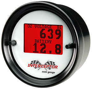
I might end up using this baby for a add on to replace my aftermarket temp guage
This thing scans and tells you everything, It hooks up to your obd 2 port,
[This message has been edited by 86fieroEarl (edited 07-17-2006).]
IP: Logged
04:47 PM
Riceburner98 Member
Posts: 2179 From: Natick, Ma, USA Registered: Apr 2002
just got more info on that scan gauge, It doesn't scan for KR (witch is a shame) I was going to order this on friday because it was cheaper then me buying a laptop and the software But now im going to have to go with the laptop and im going to be using the Alex peper software and cables, The alex peper software scans for KR.
I totally wish this thing scanned for KR as well.
IP: Logged
08:00 PM
Riceburner98 Member
Posts: 2179 From: Natick, Ma, USA Registered: Apr 2002
Well now, that's false advertising for ya... Their website says it scans for Knock Retard, and even shows an installed picture with the display showing a KR reading... Why would they show that and not actually have it available? That's mighty odd... (edit for post below - let's hope it does! I'll order one as soon as we know for sure! Likely get one anyway, as one of the vendors has them through the end of the month for $209 shipped.) BTW - keep it up with the wiring!! People are always afraid to dive into the wiring.. Just takes time. Wish the previous owner had taken the time to do it right in the first place on mine..
[This message has been edited by Riceburner98 (edited 07-17-2006).]
IP: Logged
08:16 PM
PFF
System Bot
86fieroEarl Member
Posts: 2203 From: Orlando, FL Registered: Jun 2002
Well now, that's false advertising for ya... Their website says it scans for Knock Retard, and even shows an installed picture with the display showing a KR reading... Why would they show that and not actually have it available? That's mighty odd... BTW - keep it up with the wiring!! People are always afraid to dive into the wiring.. Just takesk time. Wish the previous owner had taken the time to do it right in the first place on mine..
On the 3800 forum someone stated it did not read for KR, Im going to give intense racing a call and ask them if this scans for KR
IP: Logged
08:34 PM
Jul 18th, 2006
86fieroEarl Member
Posts: 2203 From: Orlando, FL Registered: Jun 2002
Sweet! Can't wait to see / hear it run.. Looks like I get to finish my wiring up inside a leaky tent with the effects of a tropical storm blowing around outside this weekend! Woo! If anyone does want one of those gauges mentioned above, I ordered one from http://www.advancedprod.com/ (email the guy for payment details, he does take paypal) for $209 shipped, instead of $229+shipping. Should be an awesome way to monitor KR when bumping up the boost as we all love to do! It even has 2 extra analog inputs if you want to attach some other sensors to it, and has a record mode so you can record KR or anything else while you're going WOT then check it later. Pretty cool! No, I don't have any relation to them, just really excited about it. LOL Blows my electronics skills out of the water.
IP: Logged
07:35 PM
darkhorizon Member
Posts: 12279 From: Flint Michigan Registered: Jan 2006
I am in burning a cd right now, but when I get back outside, I will have the fuel lines on, and I know it turns over with nice spark and good timing right now.
IP: Logged
08:35 PM
Jul 20th, 2006
Riceburner98 Member
Posts: 2179 From: Natick, Ma, USA Registered: Apr 2002
Saw the video, good job!! Any thought of cutting down the trans. dipstick? I took about 6-7" off the tube, same amount off the flexible stick - it pops out of the handle with a roll pin, just cut from the top and re-drill the hole for the pin. It looks like it blocks the view of your purdy S/C. LOL
IP: Logged
08:29 PM
darkhorizon Member
Posts: 12279 From: Flint Michigan Registered: Jan 2006
lol, and the view of my ign coils sitting on the top of the SC :\ heading out to fix that now.
well, Adam, might want to look over your charts again, and notice that you have pin blue 5 in there twice........ so my check engine light doesnt work, and I seem to have a highspeed fan turning on all the time (J/K).
IP: Logged
08:58 PM
Jul 21st, 2006
darkhorizon Member
Posts: 12279 From: Flint Michigan Registered: Jan 2006


 )
) 


 The IMC harness can be left the way it is.
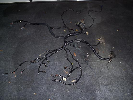


 But now im going to have to go with the laptop and im going to be using the Alex peper software and cables, The alex peper software scans for KR.
