
 
     |
| The White Bug (Page 3/42) |

|
pmbrunelle
|
JAN 08, 12:35 PM
|
|
I'll keep the Bully in mind. When I bought the RAM, I didn't do much research, I just picked an obvious choice.
Auto modification is a pretty expensive (at least the way I do it) hobby to have, and as most parts vendors are in the USA, I'm sending a lot of money outside of our country.
I kind of feel some remorse over what I'm doing, but not enough to stop auto modification.
For my next Fiero part, I have a quotation from an online Netherlands-based CNC machining service https://www.3dhubs.com ready to go.
However, I did send an RFQ to a local Grand-Mère machine shop, so if they want the job, I'll probably order from them.
|
|

|
hercimer01
|
JAN 12, 12:06 AM
|
|
|
|
|
pmbrunelle
|
FEB 09, 03:53 AM
|
|
I (nearly) finished the distributor!
Since I want to run sequential fuel injection, just the crank sensor alone is not enough.
When the computer reads the double-notch on the crankshaft, that corresponds with TDC compression #1 AND TDC compression #4.
How to tell the two TDCs apart?
Following the double-notch, the computer will poll (read) the value from the distributor sensor, which shall be different for TDC #1 vs TDC #4.
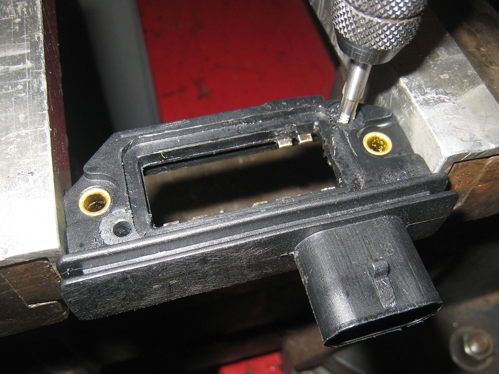
For the electronics, I started by gutting some el-cheapo ignition modules. I just wanted them for their cases.
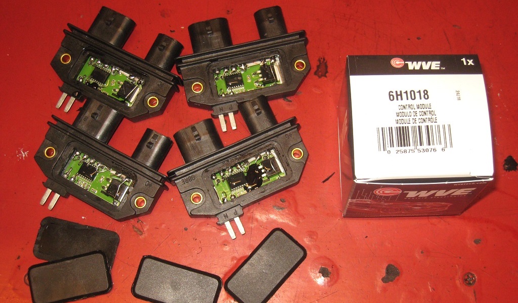
Modding the cases slightly so they can accept a PCB on top.
Someone who knows Fieros might notice that something's not stock when they see the coil connector on the left is missing.
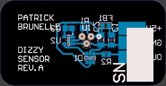
Drawing the PCB on the computer:
A view of the module's interior, before closing it up:
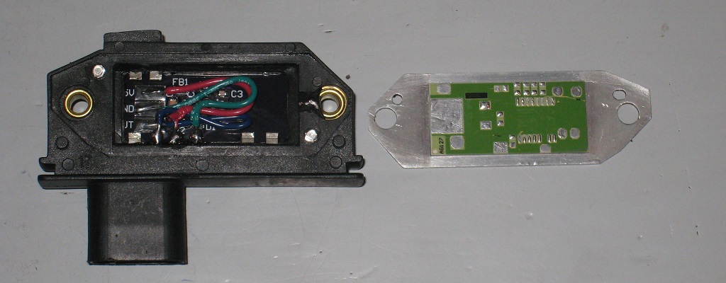
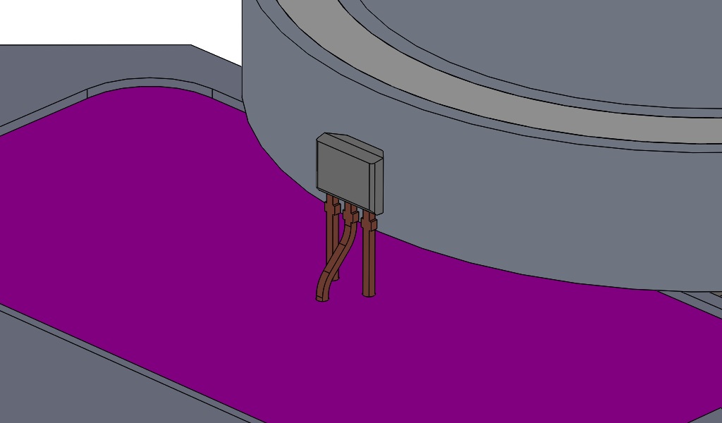
Mounted on top of the PCB in through-hole fashion is the Allegro A1250 Hall-effect bipolar latch.
The legs are splayed to improve vibration resistance, and to make soldering easier.
Depending on the polarity (North or South) of the magnetic field going through the sensor, it will output zero or 5 volts.
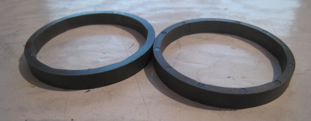
These magnets are leftovers from work. They are isotropic injection-molded NdFeB with a PPS binder.
These particular examples have been diametrically magnetized.
One side of the magnet has a North pole; the other side a South pole.
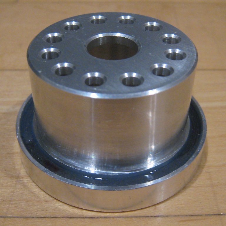
The magnet is located in a groove in an aluminium hat (made by 3dhubs).
Silicone potting compound encapsulates the magnet to keep it in place and to protect it from the ozone.
The 12 mounting holes allow me to time the hat such that the North pole is centered around TDC #1, and the South pole around TDC #4.
Or vice versa; the polarity requirement can be switched in software.
The distributor was gutted and modified to accept the aluminium hat:
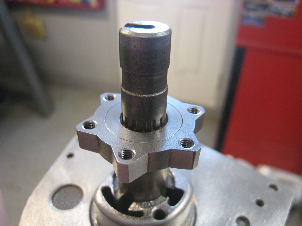
Here is the assembly:
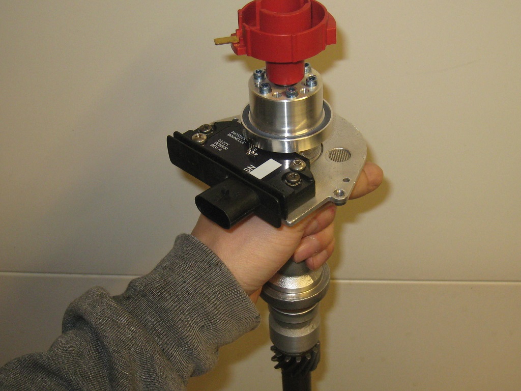
All it needs now is some conformal coating to protect the Hall sensor, and some RTV to seal it up. Maybe a dab of RTV behind the Hall sensor too. Last, but not least, these modules need serial numbers.
|
|
|
|
Spadesluck
|
FEB 09, 11:04 PM
|
|
|
|
|
pmbrunelle
|
MAR 23, 01:11 AM
|
|
I figured that an air-to-air intercooler would be tricky to package (at a minimum involving bodywork + sanding), so I felt like trying a water injection system instead. NACA Report No. 756 describes the increase in boost pressure made possible (due to knock suppression) by water injection on a test engine... so why not try to duplicate those results?
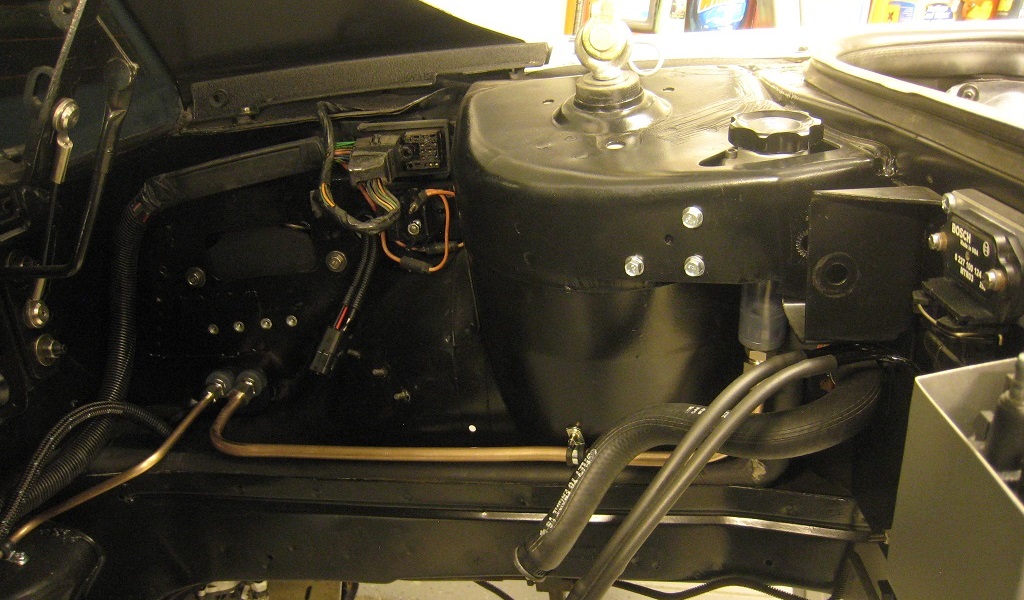
This is the water tank I made. It is made of CNC-cut rigid PVC plastic panels glued together (with plumber's cement). The Holley water/meth pump (a re-labeled Shurflo diaphragm pump that I paid too much $$$ for) sucks water from the bottom of the tank.
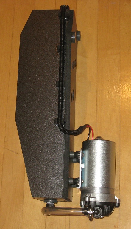
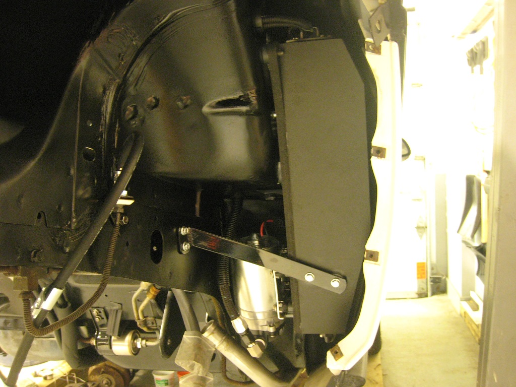
The tank fits behind the RH quarter panel. No modification to the wheelwell liner is necessary. The top of the water level sending unit is visible; it drops into a hole at the top of the tank. This will allow me to install a water level gauge in the cabin, at a later date.
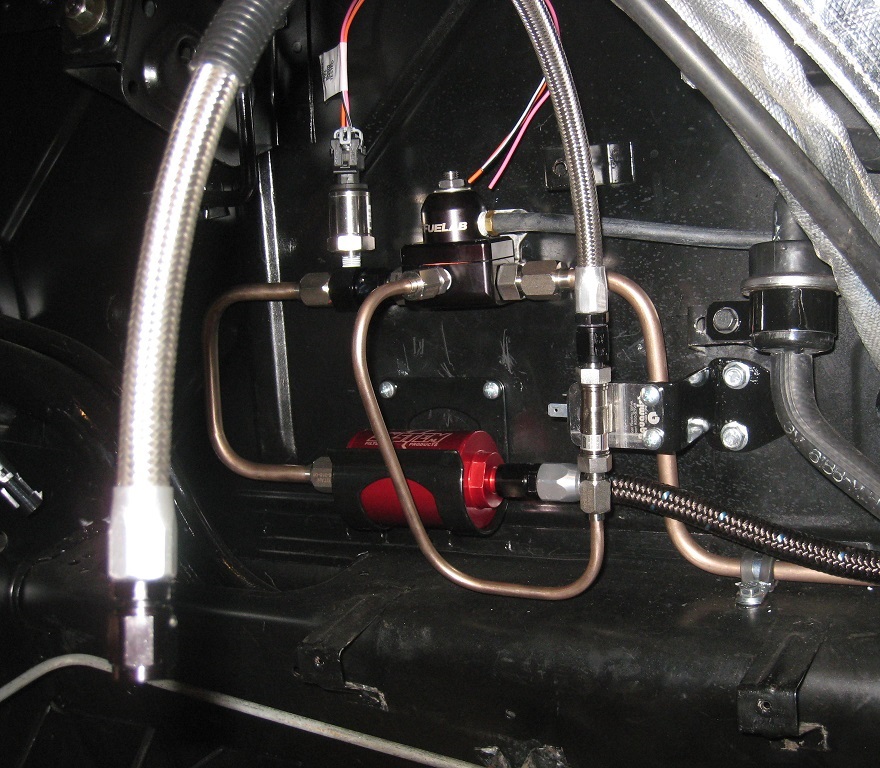
The first stop after the pump is the filter. From there, the water continues towards the pressure regulator, which is referenced to manifold pressure. A 0 - 5 V pressure transducer will allow the ECU to monitor the water pressure. Pressurized water is supplied to an Aquamist solenoid valve. A stainless braided hose carries the water from the solenoid valve to the engine. Since I'm using a return-type regulator, excess water is sent back to the water tank via the return line.
The connections to the water tank are below the battery tray (hence the battery tray is screwed in place, not welded). On the left is the return from the regulator. On the right, the fill line.
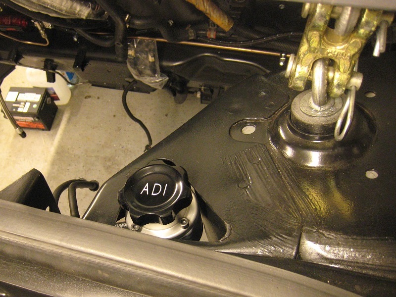
This is what the fill cap looks like from up above. I decided to engrave "ADI", which stands for Anti-Detonant Injection.
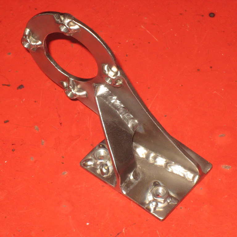
Here is a steel mount i made for the filler tube. Like most steel parts I make for this car, I sandblasted and POR-15ed it.
Another post detailing the intake tract mods for the water injection will follow!
|
|
|
|
tshark
|
MAR 23, 07:21 AM
|
|
|
Just asking, but does the high-volume oil pump give you high oil pressure?
|
|
|
|
pmbrunelle
|
MAR 23, 10:10 AM
|
|
There's a rudimentary "pressure regulator" in the oil pump cover (a flat disc and a spring, IIRC), so no, you don't get more maximum oil pressure due to the pump being high-volume.
However, at low RPM, when the oil pump isn't spinning fast, you'll have more oil pressure from the high-volume unit.
I'm using the Fiero 2.8 oil pan, so I decided that I wanted to use an oil pump sold for the Fiero 2.8, so that its pickup tube would be suited for my pan.
When researching whether I should use the standard-volume 2.8 pump or high-volume 2.8 pump, I found out that the high-volume 2.8 pump is the same pump as the standard pump sold for later-model 60° V6 engines, except for the Fiero-style pickup tube.
I figured that I couldn't go wrong with the standard pump for later generations of this engine family. I'm assuming that GM changed the volume to address some sort of reliability problem with the early incarnations of the 60° V6 (I might be wrong, but that's my guess).
|
|
|
|
pmbrunelle
|
MAR 23, 05:59 PM
|
|
I re-purposed the IAC passage in the Fiero intake manifold for the water injection system.
After the machine work, I had the intake plated with electroless nickel (thanks olejoedad for advice) to protect it from corrosion due to the boost juice. Unfortunately, it doesn't seem to hold up to the methanol in windshield washer fluid, so I'll most likely be using distilled water from the pharmacy. I'll have to take some special precautions for winter storage of the car (maybe a purge with 50/50 antifreeze).
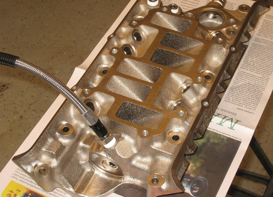
Water enters the main gallery, where it then goes out to the six ports.
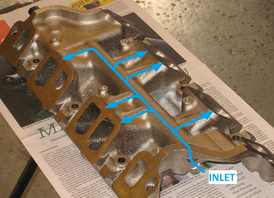
The IAC passage outlets were drilled and tapped to 1/8" NPT. Just enough material was removed to clear the socket I intend to use for nozzle installation.
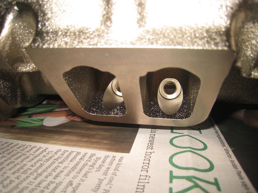
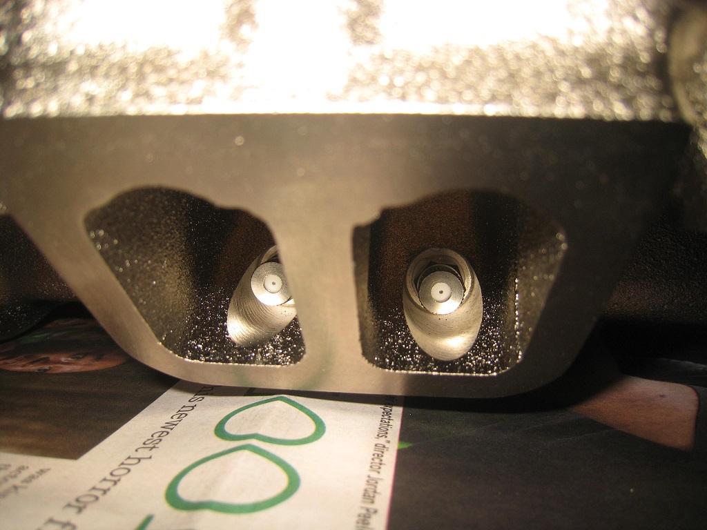
Here, the nozzles are installed. Since I used a gel-like thread sealant, I'll wait until next weekend before starting spray tests with water; I want to be sure that the sealant has cured.
The nozzles look like this (stock photo):
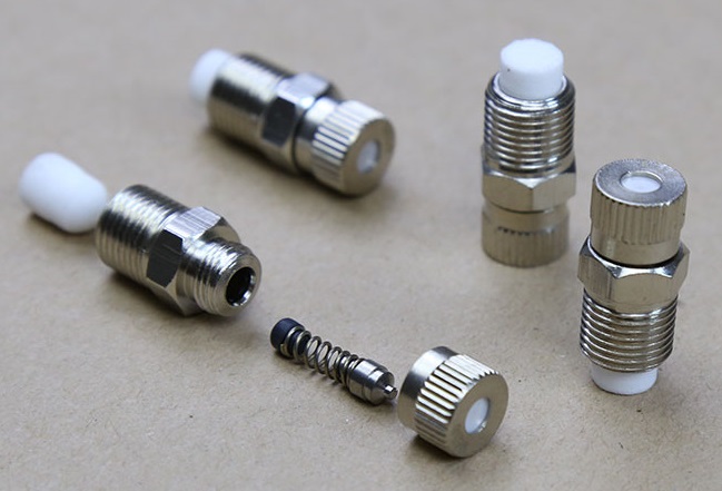
The nozzles use stainless steel construction, and include both a filter and check valve. The check valve will keep the IAC gallery full and primed after injection, ready to spray for the next shot.
Following advice from Blacktree, I selected check valve springs that are stiff enough to maintain a pressure of 35 psid when closed, to prevent the water from boiling off. Unsurprisingly (when you buy things from alibaba), the non-specified stock springs were no good for my application; I ordered three kinds of springs from Century Spring and I picked the ones that worked best.
****************************************
Since I repurposed the IAC passage in the intake manifold for water injection, what to do with the IAC airflow?
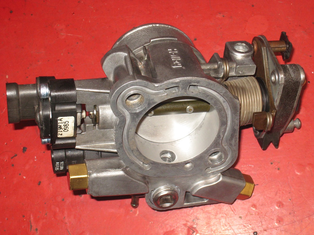
I plugged the stock IAC outlet, and by drilling an angled hole, the IAC airflow is re-introduced immediately after the throttle plate. Since the angled hole intersects the throttle body's coolant passage, I also blocked off the coolant ports (my Fiero won't have the throttle body heat feature anymore).
|
|
|
|
Spadesluck
|
MAR 23, 07:43 PM
|
|
I like the way you blocked of the ports on the TB. Never thought about using brass plugs to clean that up. Do you remember the pitch of those plugs by chance because I would like to steal your idea! 
|
|
|
|
pmbrunelle
|
MAR 23, 11:26 PM
|
|
Those are actually the stock brass tube nuts (with their O-ring seals) that come with the factory coolant lines. In my setup, these plugs have to seal well, or else I'll have a boost/vacuum leak.
Since the tube nuts have holes in them, I soldered in a piece of scrap steel rod with plumber's solder and flux. I then faced the ends square and smooth on the lathe. Someone without a lathe could use a hacksaw and file to achieve an equivalent result.
When you look at the modified piece from the end, there's brass on the outside, and steel on the inside. So, I painted the end black to hide the inconsistent materials, and since unpainted steel would rust anyway.
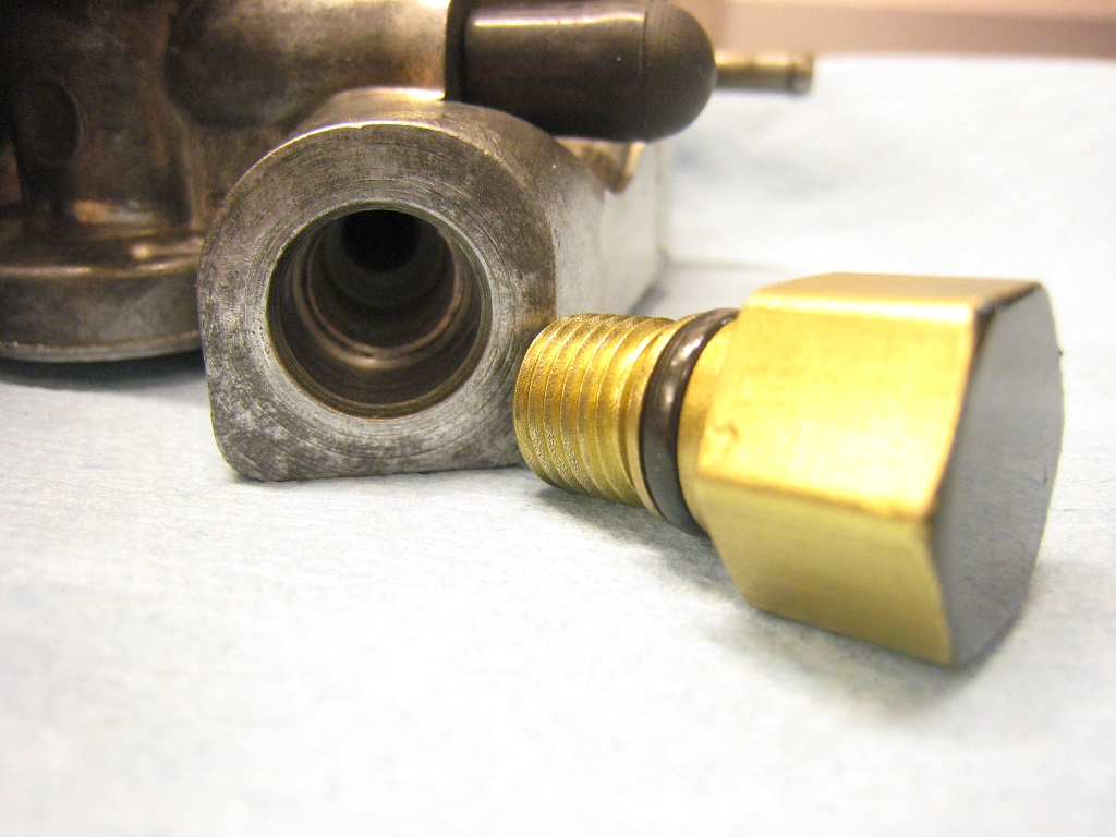
In your case, if you don't have the stock tube nuts anymore, I can think of two alternatives:
1. Try something threaded, such as a bolt. The measurements of the factory tube nut are consistent with that of a 7/16"-20 UNF thread.
The under-head length of the factory tube nut is 5/8".
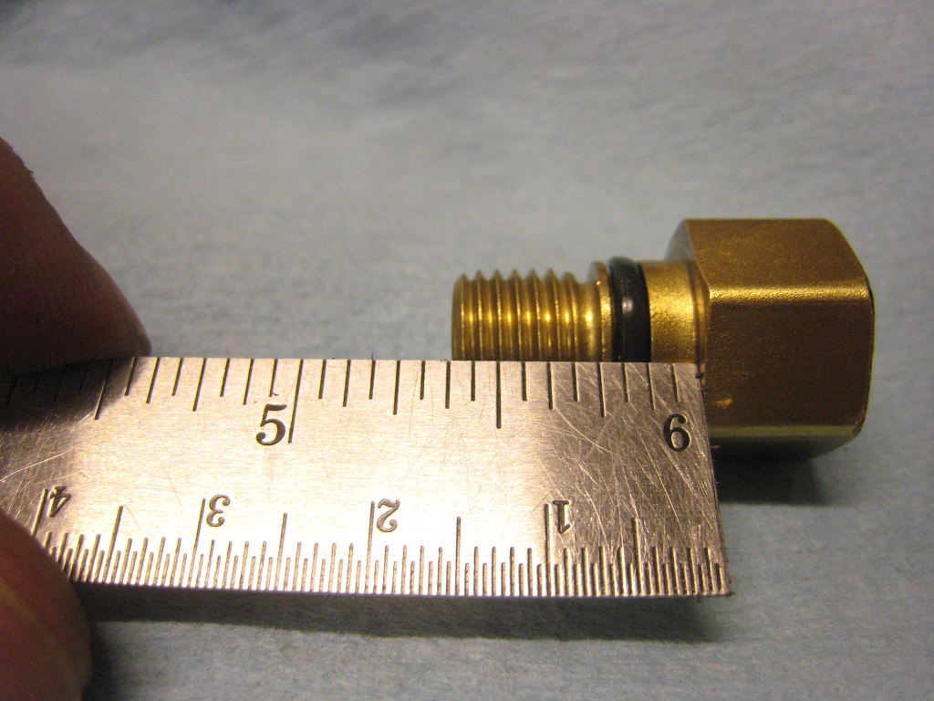
2. Tap a freeze plug into the counterbore, which measures 12 mm in diameter.
After a quick search I found these which would probably work:
Melling MPC-108 (normal freeze plug)
Melling MPC-108V (with small venting hole in the middle)
|
|
|
|

