|
| Bringing a 88 Fiero Back to Life with a LFX Swap (Page 5/15) |

|
MikesFirstFiero
|
OCT 09, 09:19 PM
|
|
Dennis, Thanks for the compliment. I'm really a retired controls engineer for elevators with responsibility for hardware & software design with a side of mechanical engineering as needed. I'm pretty good at design and still a crap-to-fair welder. I've never done enough of it to be come competent. But I'm improving.
The trick to this swap was to buy the whole car and rip out everything electric/electronic. I bought the Mitchell1DIY service for the car so I could figure out where things go. Right now by process of elimination I have the ECU, BCU(talks to everything), SDGW (Serial Data Gateway), CCM (Chassis Controller, runs fuel pump & Evap), Keyless Entry Module, Push to Start, Brake Switch (needed to start), Shift Knob(for manual shifting), Gas Pedal and Instrument Cluster. As long as these are connected the car will start and run. As far as the power train goes it doesn't know it is in a Fiero. 2018 & later GM cars have vehicle-specific encoding in some modules, the shop manual doesn't say which. So if one of your modules fails you must take the replacement to someone who can code it for your car (Your local friendly Chevy dealer!). And who knows if they would touch a swapped engine.
Right now I've got all kinds of warnings but it still runs to the redline making power. I guess most of the DTCs don't matter other than being an inconvenience. Once I'm further along I'll figure out how to get rid of them. Today I'm trimming the instrument cluster along with the steering wheel switches for cruise control and display management to fit in the Fiero panel bezel. Tight fit but it should work. I just follow the wiring diagrams and eliminate the unwanted (and Big) connectors. So far most things work OK. My only real unknown is when I push to stop the engine does but goes into accessory operation. I flip my battery master off and it resets.[This message has been edited by MikesFirstFiero (edited 11-29-2021).]
|
|

|
zkhennings
|
OCT 11, 02:07 PM
|
|
|
Very cool and very clever solutions to problems, I look forwards to seeing video of it driving! [This message has been edited by zkhennings (edited 10-11-2021).]
|
|
|
|
MikesFirstFiero
|
OCT 18, 11:54 PM
|
|
I did bleed the brakes again since the pedal was low, found some air in the system both front and rear so now the pedal feels much better. I've been putting the hours in but the progress for this work seems glacial, wiring takes forever and I have done lots of that kind of work. Messing with a complete harness means everything should work but there are lots of wires & connectors you don't need that must be figured out and eliminated. The goal is to get all the operating controls where they belong so it is safe to take on the road with other traffic. Pulled out the gas pedal to lower the pedal position closer to the firewall by an inch and to add a stiffener rib on the back to make it less flexy. Rerouted the gas pedal cable to where it needed to be since it temporary. Extended the push-to-start cable and put the switch in the dash. Moved the gear indicator and shft knob wiring to be in the center console. Put the brake switch in the center console for now. Will eventually add it to the brake pedal; don't need it for the brake lights yet. Eventually will need it so the brake, tail and turn signals are driven from the Impala controls. For now only reason for it is to start the engine since the lights are all Fiero. The key FOB is cable tied to the keyless sensor now so you push the PTS button and it starts. The transmission must be in park too but that's done with software and a internal transmission switch in the TCU.
The old ECU mount was adapted to hold the Body Control Module
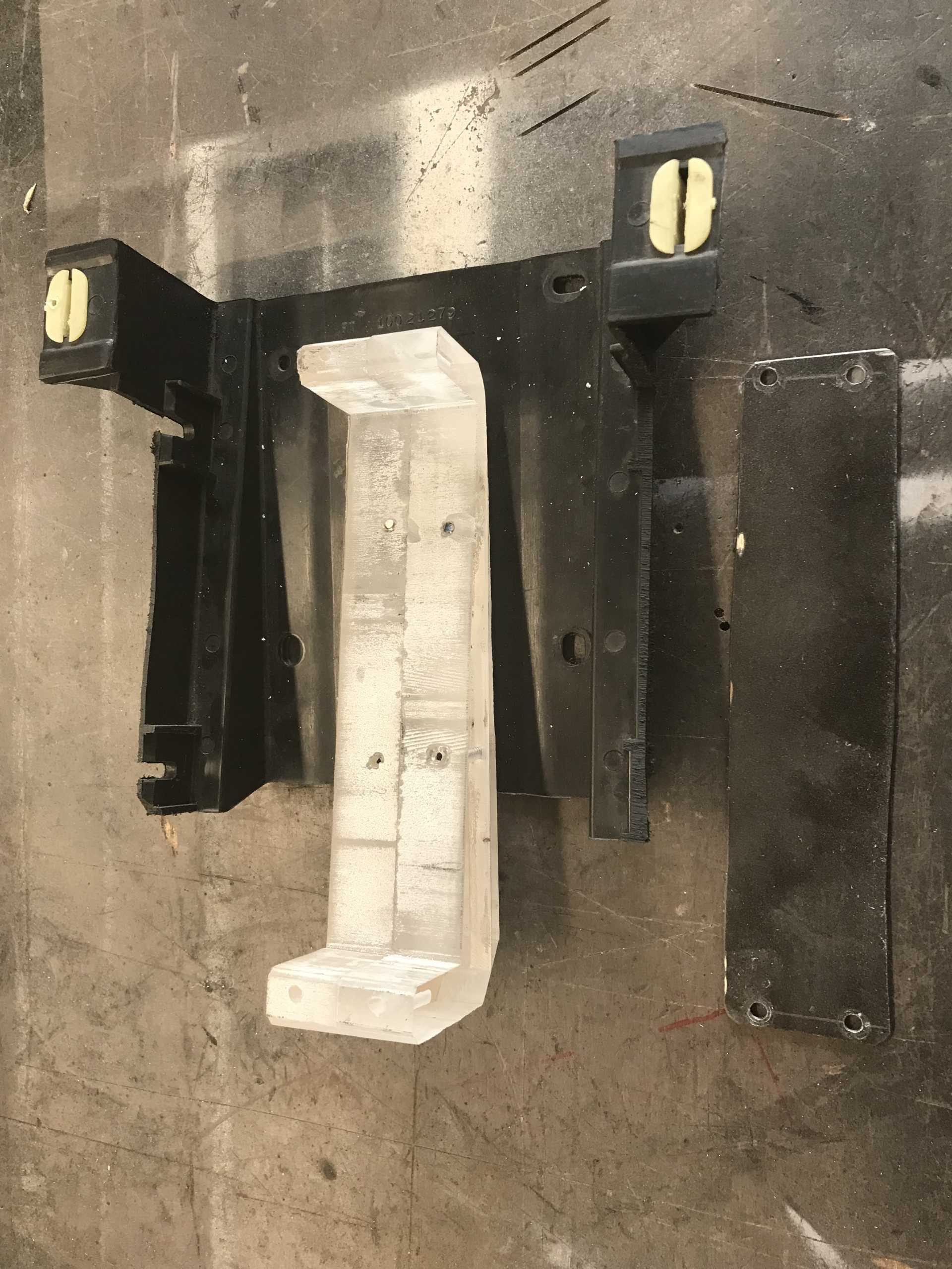
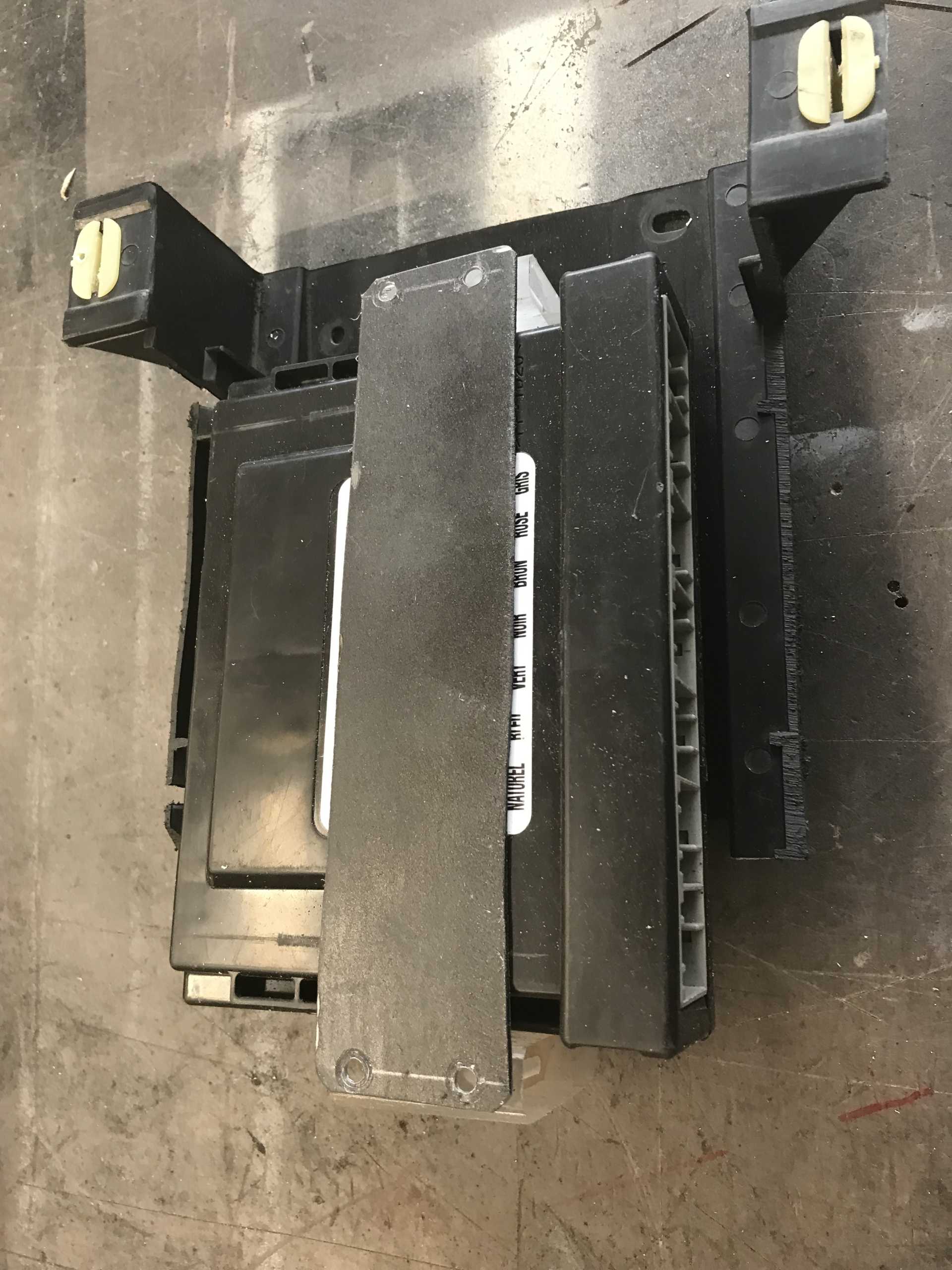
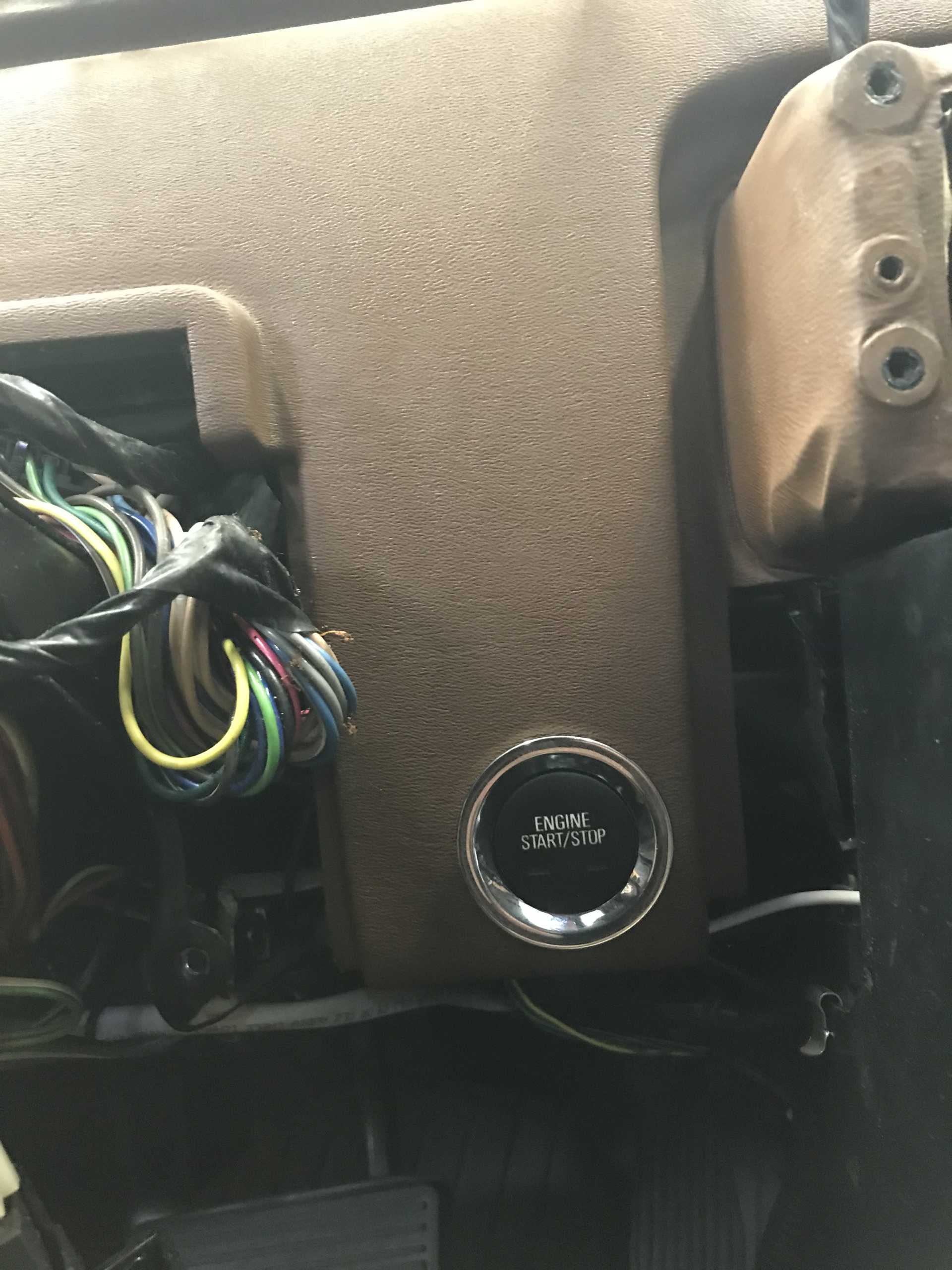
Push to start hidden behind the Instrument Bezel
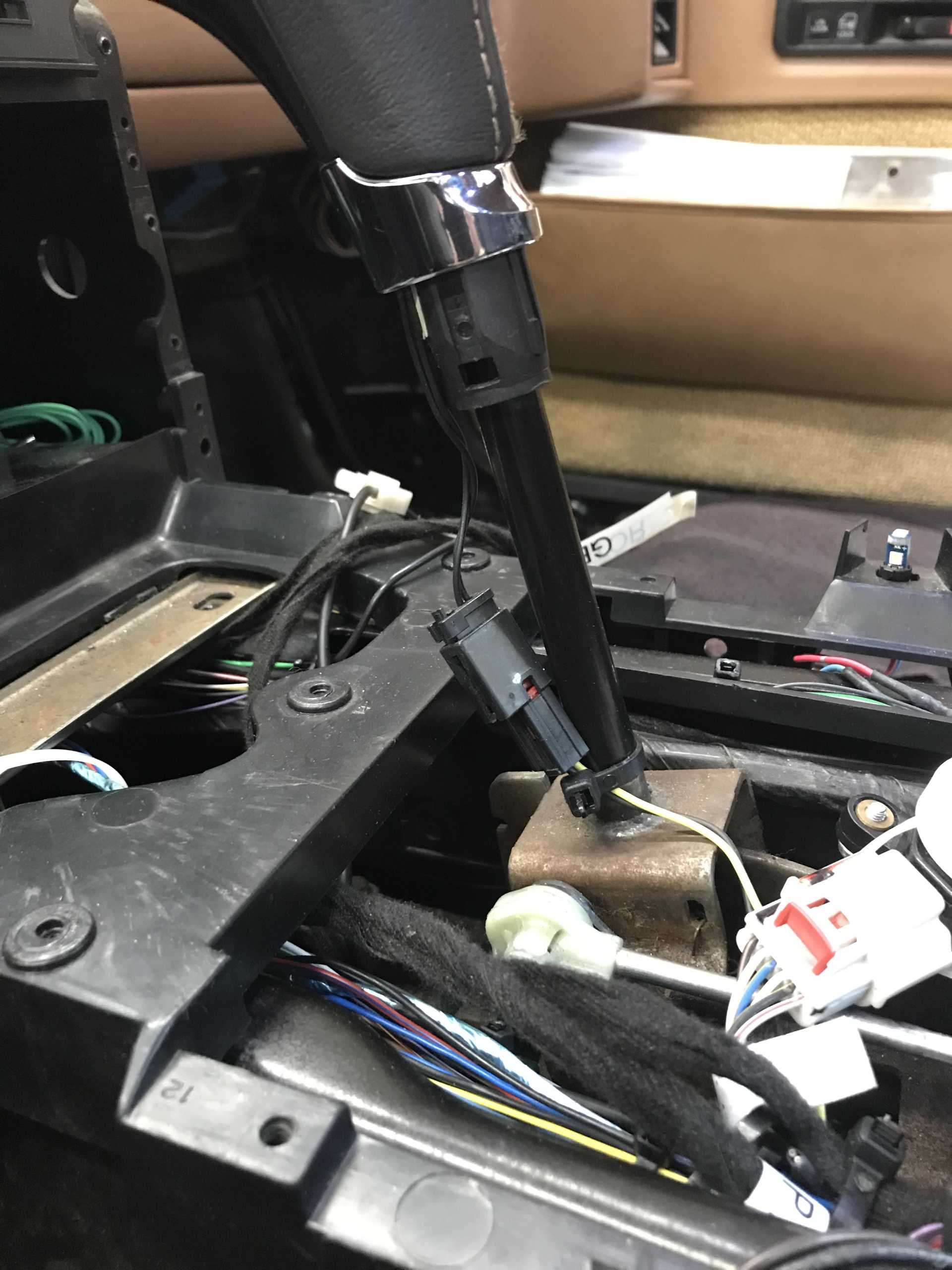
Wires to shift knob for manual shift up/down
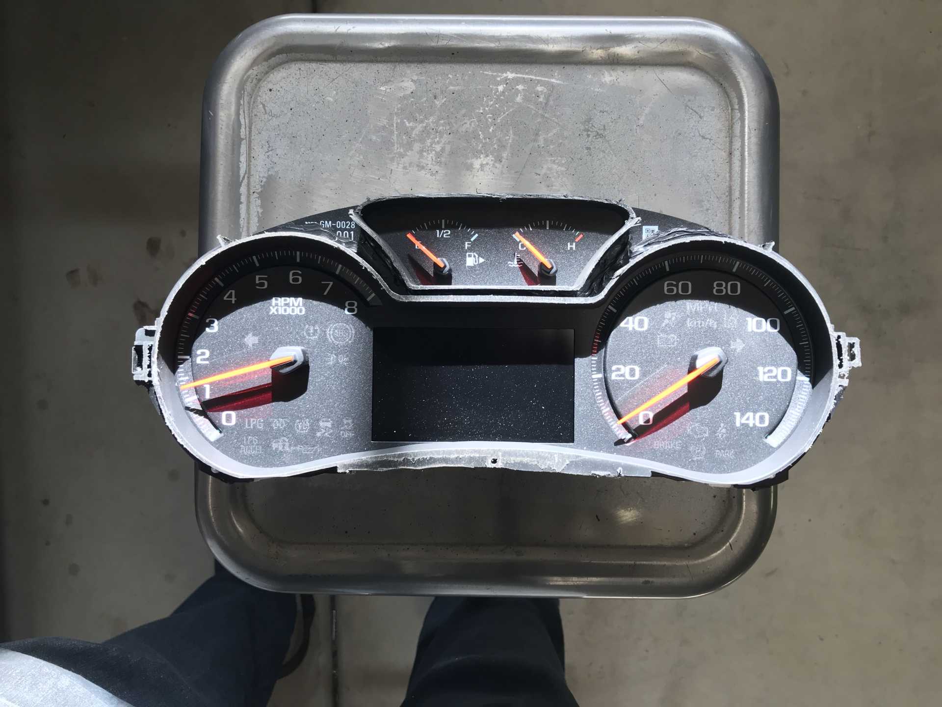
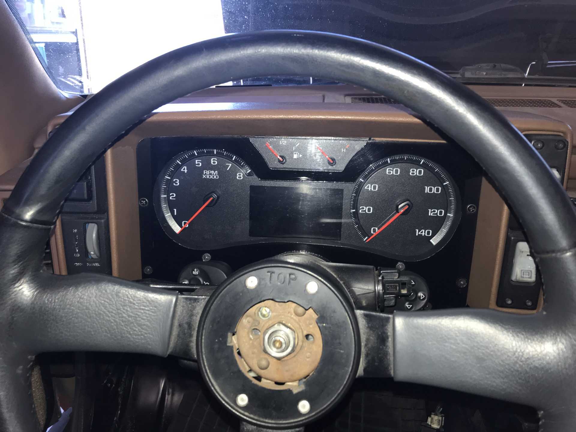
Started working on the instrument cluster. The idea is to retain the original cluster bezel, remove the Fiero parts and add in the Impala cluster and the left and right Impala steering wheel switches for cruise control and display selection. I'm not going to add them to the Fiero wheel since would be very un-original and look ugly, it wouldn't fit well and requires several wires to be run in the steering column. The switches will go below the instrument cluster. First step was to cut the Impala cluster so it is thin front to back. The original has glare shields and is much wider at the top (7"). It needs to be like the Fiero, just a vertical thin flat box. Then cut off almost everything sticking out to reduce the top to bottom and side to side size. Luckily I have a bandsaw and the trimming took an hour with no mistakes. If you are into wood working and don't have a bandsaw, get one you will love it. I see them at estate sales all the time for cheap. I decided to make the IP front cover from a 1/4" thick piece of transparent acrylic which was cut to the shape of the original trim plate. The cluster and new switches will mount to the back and the whole thing will be held in place by two screws on the sides and the top of the cluster which extends up above the bezel to lock it in place. It sounds simple but there was a lot of head scratching to make it fit securely and look good. The switch outlines are mirror images of each other and are oddly shaped. How to cut this funny shape in a piece of plastic? This is a long process, you might want to look at the photos to make sense of it. I remembered a trick I used for panel layout in the past. First I took photos of the switches and instrument cluster frim directly above them so there is no distortion. Then the photos were printed on my computer until the image size was the same as the actual part by changing the printer scaling factor. This photo was cut out and the outine of the switch was marked on a thin sheet of acrylic as a marking aid. This marking aid was then cut out with my portable router and filed & sanded until the switch fit correctly. Next step was to transfer the outline to a small piece of 1/4 acrylic as a template which was also routed and carefully trimmed until the switch would fit (only needed to do this once). Note that the switches do not mount flat, but are tilted up and outwards which changed the shape somewhat. Then the mounting holes for the switches were added to the template. Now I have a replica of what each cutout and mounting holes will look like. Almost there now.
Taking the photo used for masking the acrylic panel
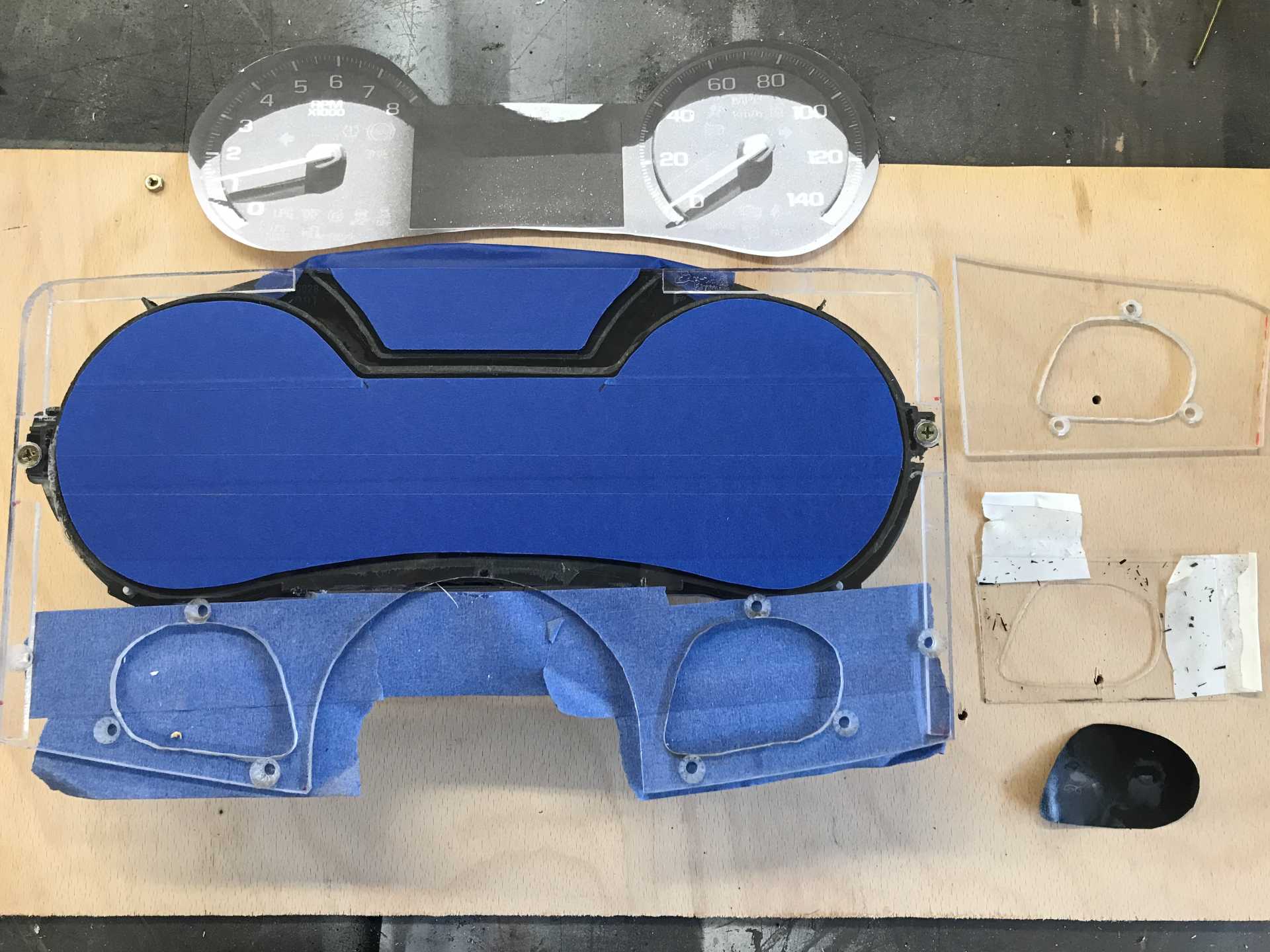
The painting& cutout prep items talked about, left is the photo&masked panel. Right is the cutout photo & templates
The switch template was cut to fit along the edge and bottom of the face plate and was placed where the switches go. Then the switch mounting holes were drilled on the real panel and countersunk. The template was mounted to the real panel with the mounting screws to hold it in position; now I've got a really good pattern to make two identical holes. Time to get out the router again with a laminate trimmer bit. After cutting a small hole in the center of the real panel cutout, the trimmer bit was used to widened it until it was an exact duplicate of the template. Only the template needed to be precisely trimmed, the real cutouts were just copies of the that and needed only light sanding to eliminate rough edges. Cutting acrylic with a router is a messy and fiddly process; you must go slowly and look like a snowman when done. If your router speed is too high the plastic will melt. If you are to agressive the bit will dig in and destroy your work. Always cut into the bit rotation since going the other way usually leads to disaster as the bit tries to race ahead.
Disaster didn't happen (this time, other projects haven't been so lucky) and the panel was almost ready for painting. The panel was cleaned and some scratches from routing buffed out. Then cluster and switches were mounted to the panel to check the fit; the switches were removed (while trying not to touch panel surfaces). The photo of the instrument cluster was laid on top and trimmed until it was slightly smaller (1/16") than the actual cluster openings This means the edges cut on the bandsaw were hidden. Luckily there was a straight edge on the cluster cutout that could be used as a guide. I removed the photo and placed a piece of painter's tape on the panel along that straight edge inset by the 1/16". The photo was placed on top of the tape and marked for left-right position. Then the photo was removed and more tape was placed over the entire instrument area. Tne photo was replaced and lined up to the marks and held with bits of tape. The tape on the panel was cut to the outline of the photo very carefully with a sharp X-acto knife and the excess tape removed.
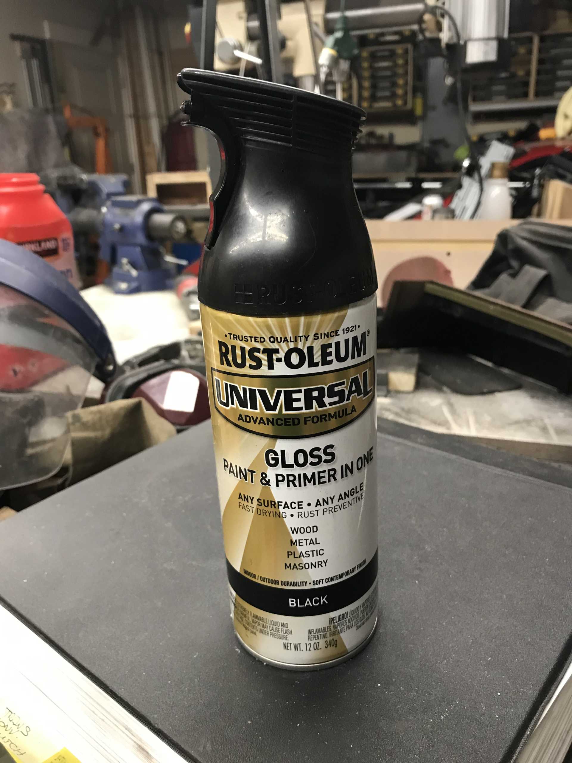
Finally after 12 hours of making templates, cutting, fitting, trimming, cleaning, taping and cutting the tape outline, the panel was sprayed with Rustoleum Universal. It is a really good rattle can. It needs to be used exactly as the manufacturer specifies. It is the only spray can I've found that gives a true 6-8" fan pattern like a real gun, almost like HVLP in a can. Clean work is essential, double coat within 5 minutes or wait a day or two before applying the next coat (or it will craze). And it is very slow to dry. Figure 24-72 hours. But the results are very good for a $7 can of paint.
This is the stuff I used
And the result. Not perfect but good for a first try.
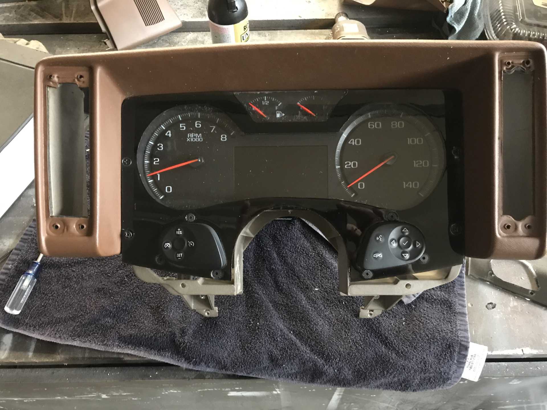
Mounted in the car
Now that this is complete I'm working on getting rid of unwanted wiring and connectors. Most of the connectors are huge and won't be needed. The goal is to verify everything working in place and then dispose of the connectors, checking that something needed hasn't been removed. Then the interior can go back in. Also the heater AN fittings showed up so with winter coming they will be hooked up and the coolant (water) replaced with the real stuff. Then I tackle the air filter & hose to the MAF & TB.
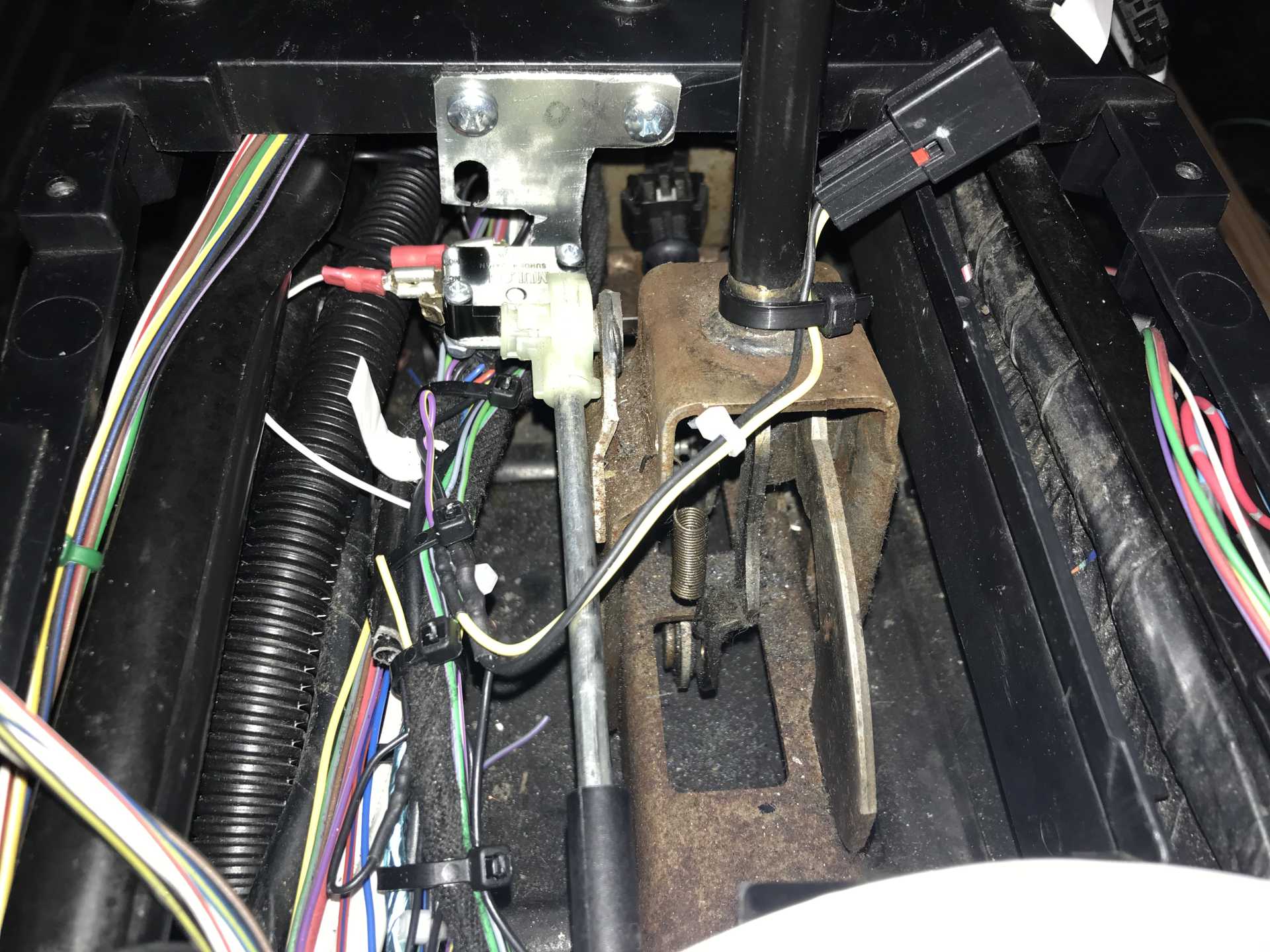
Spent a day messing with the wiring for the Instrument cluster and mounting the cluster. It fit nicely and the wiring seemed to work out right. Then I went to start it; turning on the battery master caused the PS pump to kick in??? That's not supposed to happen. So I pushed the PTS to see if it was totally dead and it did start and idle. But the display was black and the gas pedal did nothing. Sigh, time to dig in and figure it out tomorrow. A few hours later I remembered the ground for the display was left off. Maybe that will solve the black display. The PS pump running indicates the Hot-in-Run signal is always active. No idea what is up with the gas pedal. Sure enough putting the errant wire ot ground solved the IP problems and stopped the PS pump from starting while not running. But the gas pedal is still dead. I've been meaning to start cutting out the unneeded Impala connectors and decided the gas pedal was a good place to start. What a mass of wires, almost 100 in this cable. Rewiring them without the connector solved the problem. Vroom. And another obscure problem cropped up, shut off the engine and the display shows "Shift to Park" but the shifter is in Park! The electrical power does not turn off - it goes into accessory. Turns out there is a almost undocumented switch on the shifter that tells to BCU the lever is in Park. Leave the lever in neutral or anything other than Park and the system never shuts off. This switch is not required for starting the engine, only for turning off power when you stop the engine. So I added a "shifter park" switch and one more problem solved.
The Shifter in Park switch is a micro switch with an arm that the shifter yoke closes to turn off the electricity
And the final result
<How to upload a video?>
While waiting for the paint to dry on the panel I hooked up the heater hoses, the AN swivel fittings made it simple to point them where they needed to go. I did fab a pair of hose retainers from 3/4" acrylic (another band saw job). Those were hose clamped to the front cradle cross bar and run to the pipes next to the gas tank.
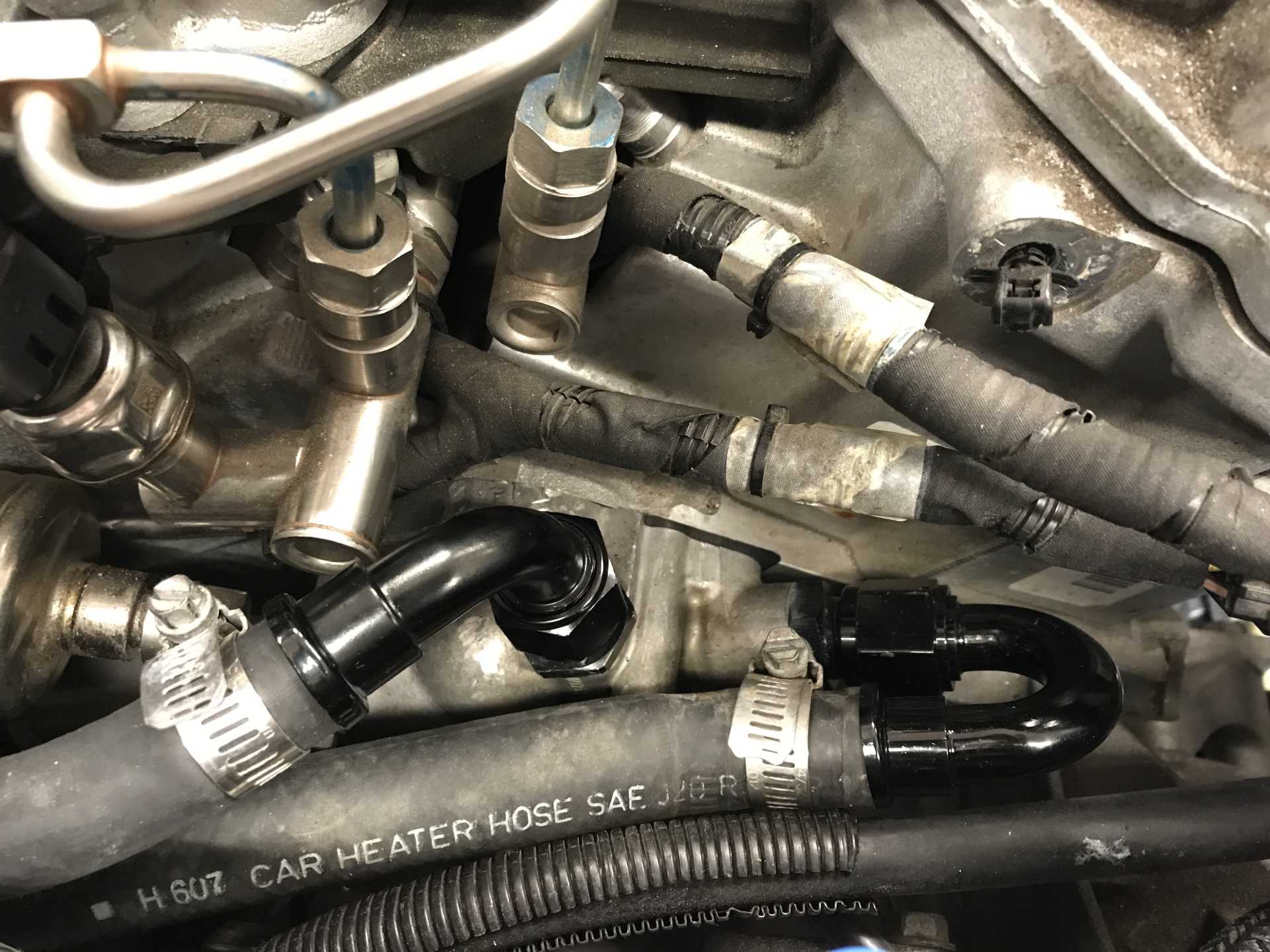
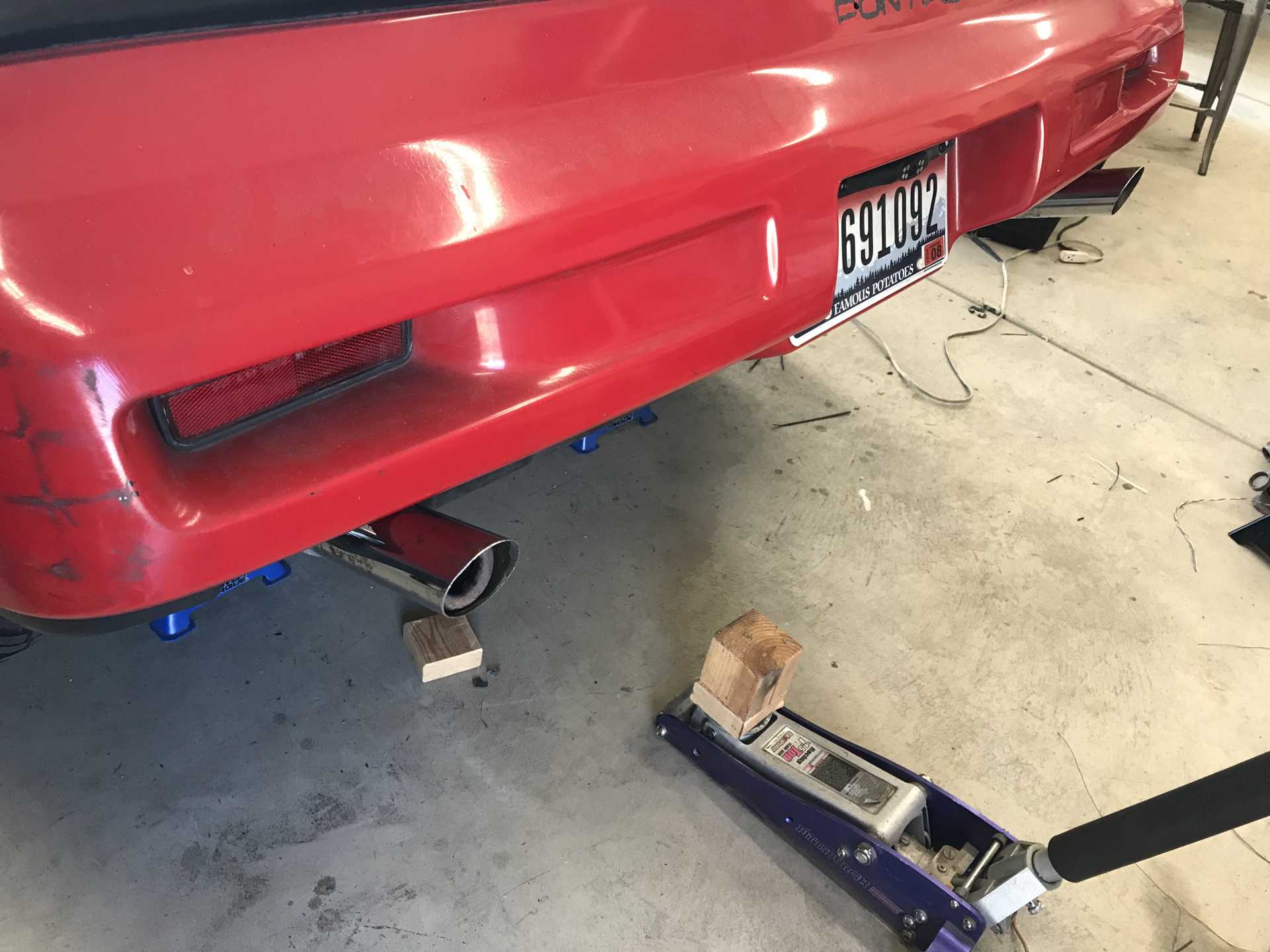
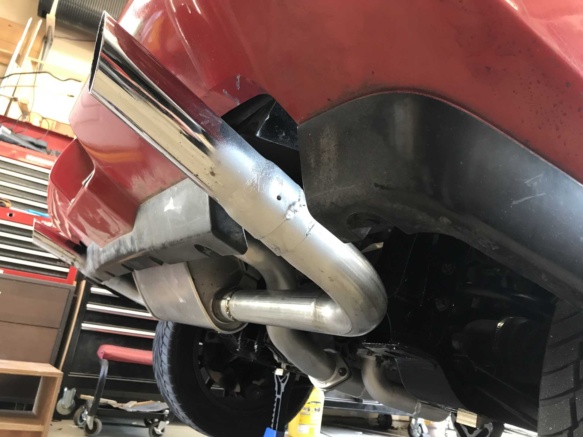
The next day I took it for a short run about 16 miles round trip. It ran well but then seemed to start running on 5 cylinders. No other problems. Since it was getting late I decided to look at it the next day. Next day's project was to add in the heater hoses since it's starting to get into the 50s around here. While walking around the car I noticed a plug wire that didn't look right. Sure enough it was not latched in place. Let's hope this solves the running on 5. My AN swivel fittings came in so adding the hoses meant removing the fuse box and MAF and working under the car. No big surprises and I started filling the coolant. Tomorrow we try driving again after I burp the system. While the ass end was up I decided to finish the exhaust pipes. The camaro muffler has two outlets, one per end. I went to my local Mr.Muffler shop (a really helpful guy) who bent two 90 degree bends out of 2.25" pipe. Took them home and added the old tips I used on the 2.8 which needed some adapting and a few hours later they were done. Those tips were a disappointment since they lost part of the plating and started to rust, hence the sloppy VHT. They do act as small resonators and make things quieter at idle and low power. I'll probably replace then with something from Vibrant which is stainless steel. Added more coolant and went driving.
This is the first time I've had everything installed and working so I cranked it up and it ran on all six; the loose connector was the cause of the poor running the other day. No leaks from adding the heater hoses. The car is quiet while cruising and gets loud only when you push it. Acceleration in all gears is nice. When in fifth gear at 50 MPH I was seeing a reported 42mpg. An untimed seat-of-the-pants pull from 0 to 60 went by pretty fast. Next time I'll take my radar detector with GPS speedo and see how far off the car's speedo is. I'll video the IP so I can calculate the speed vs time and thus the wheel horsepower.[This message has been edited by MikesFirstFiero (edited 10-23-2021).]
|
|
|
|
Rickady88GT
|
OCT 19, 07:29 AM
|
|
|
|
|
Will
|
OCT 19, 10:13 AM
|
|
|
Congratulations on the first drive!
|
|
|
|
Daryl M
|
OCT 21, 04:36 AM
|
|
|
Amazing progress! Keep the posts coming. Really curious to see performance numbers.
|
|
|
|
Raydar
|
OCT 21, 08:39 PM
|
|
That's the quickest I've ever seen such a complex swap come together. Outstanding!
Good luck going forward. You obviously know your sh!t.
|
|
|
|
MikesFirstFiero
|
OCT 21, 11:57 PM
|
|
Yes I do know quite a lot, but this is my first swap project; I made a career of updating existing elevators with new control systems so I'm used to working on old stuff and figuring out how to mount a sensor or encoder where there wasn't one before. Without the efforts of all the other swappers who posted to Pennocks I would not have near the success I've had. They have given me inspiration for the corvette brakes, battery relocation, power steering and now the LFX swap. As for going quickly, I've been able to work on it mostly full time being retired and now I'm up to almost 700 hours. Most guys work and only get to do 20 hours per week which means a long calendar time. Besides my Wife said "Get it out of the Garage by 1 November" so she can park inside when it's cold. When Momma's not happy, Nobody's happy.
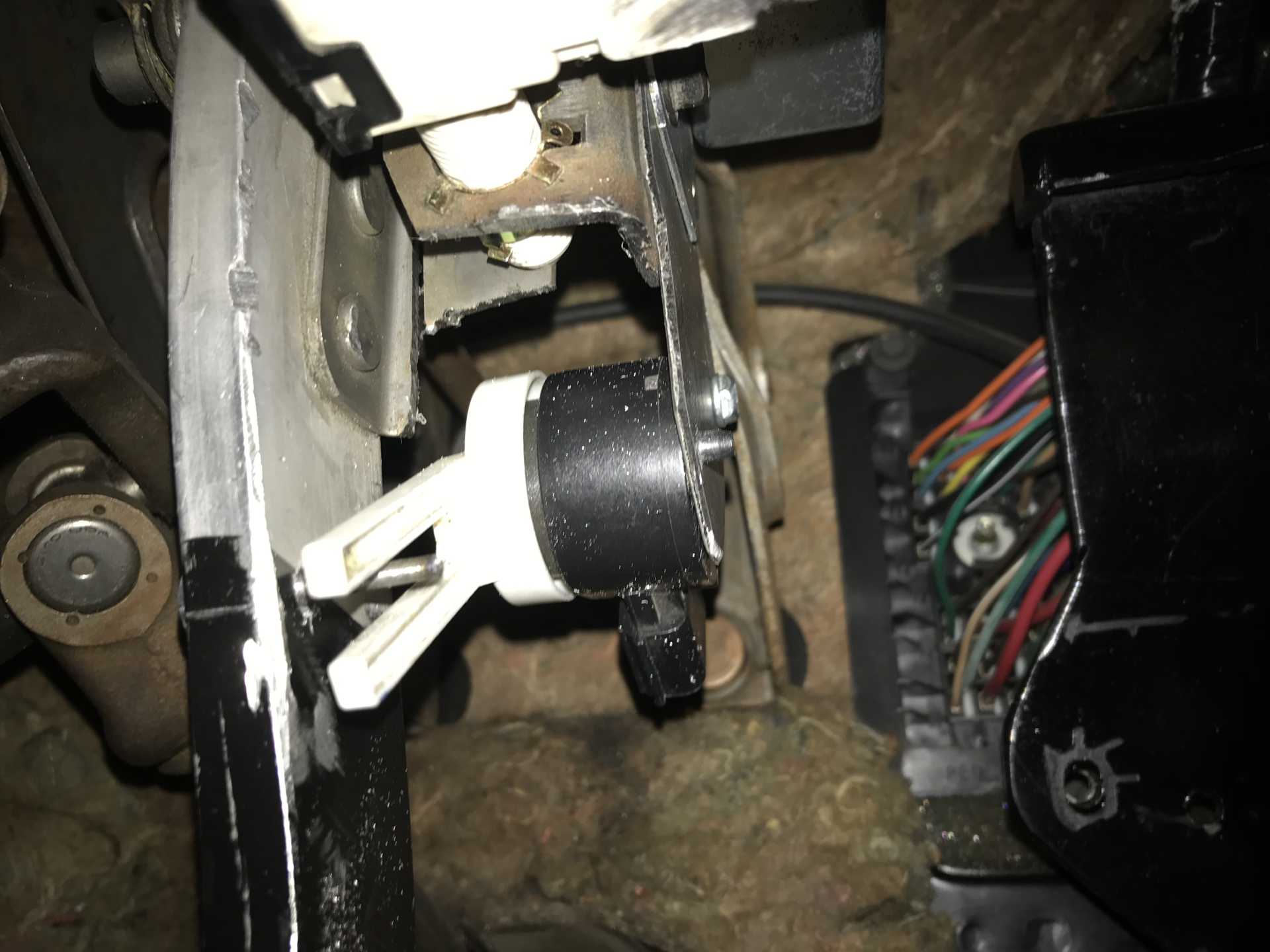
The chime has been driving me crazy, dings any time the motor is running. So I figured out where it is located and removed it. Then I decided to mount the Impala brake switch in addition to the Fiero brake switch; eventually the Impala BCU will run the stop, turn and backup lights. But while the seats are out I thought it would save time to have the brake switch working in the right place. Plus it makes starting "normal" for a modern car, press the brake & push the button. The bracket for the switch turned out to be simple but the location is miserable to get to so the shape was guesswork. A really thankless job being upside down. And yes, I made a plywood template of the bracket first before cutting metal. Turned out to be a good thing since the mounting holes were in the wrong location. Next the Impala brake switch cable has been be extended by about 4 feet and connected to the new switch. The switch is connected to the pedal arm by a pin mounted to the arm.
Original mounting holes were too close to the sensor/switch so moved them out 1/2"
Multiple holes for the pin since not sure what rotation would be needed to connect to the lever.
It's actually a dual-channel volume control (potentiometer) similar to the accelerator.
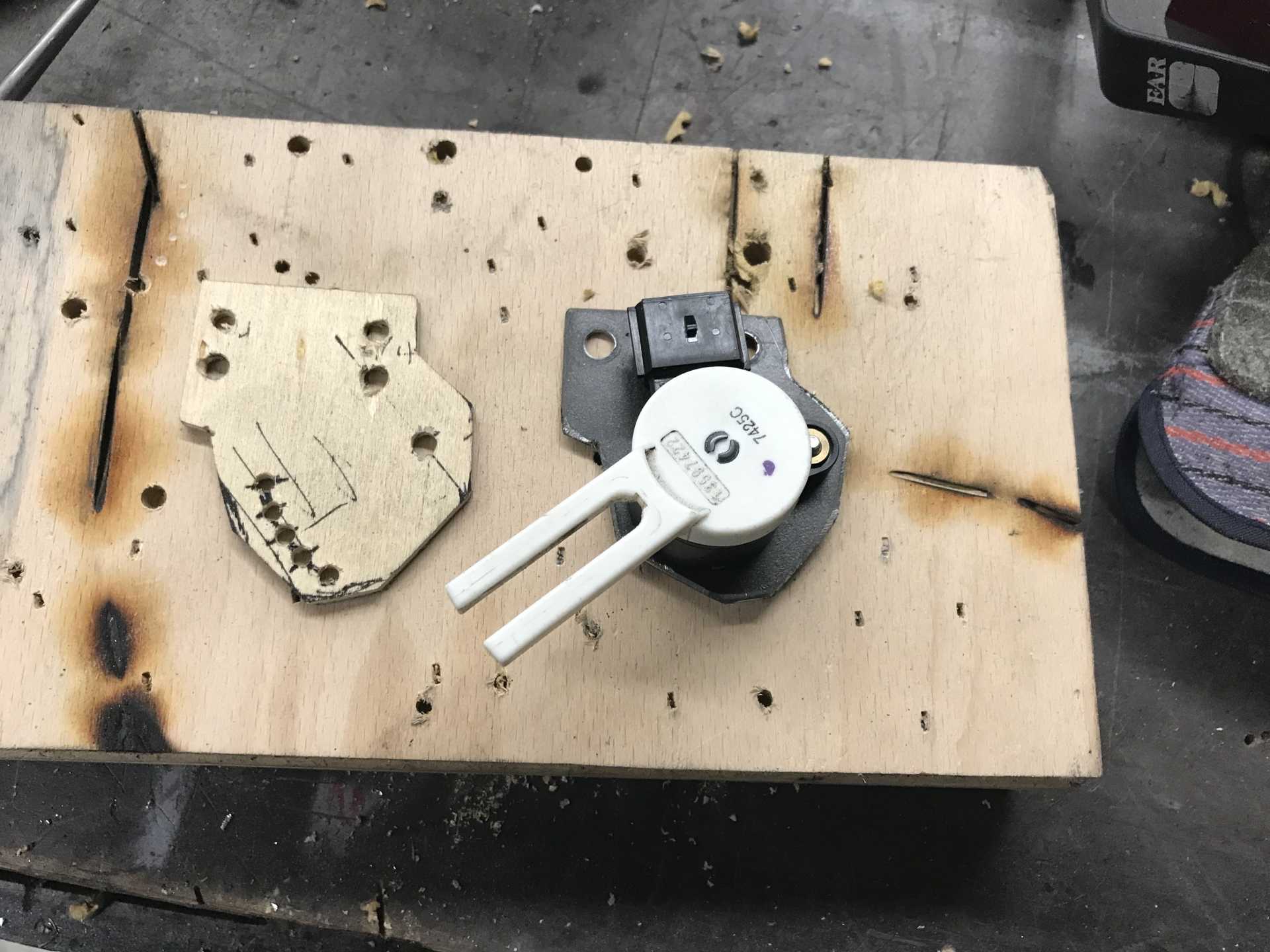
Actuator pin is a 5mm bolt with threads ground off. Lucky the brake lever is aluminum so easy to drill & tap.
By accident I left the MAF connector off and started the engine to check that I did no harm. When it started it "burped/sneezed" and continued to run. When shut off the IP did go blank but the PS pump and cooling fan continued to run?? This says that the Hot-In-Run is still active with no MAF signal present. Plugging the MAF back in made everything work normally.
Reached a milestone today, the last Impala harness connector has been cut out so now the only thing left to resolve is the internal Impala fuse block. The big one is in the engine bay, the smaller one is inside the passenger compartment. I think I will be able to eliminate the internal one since there are lots of fuses no longer used in the engine bay block. Besides there is no good place to put it in the cabin. Just need to match where the power comes from (Always On or Hot-in-Run) and the fuse current rating. Looks like I'll be able to button up the interior next week.
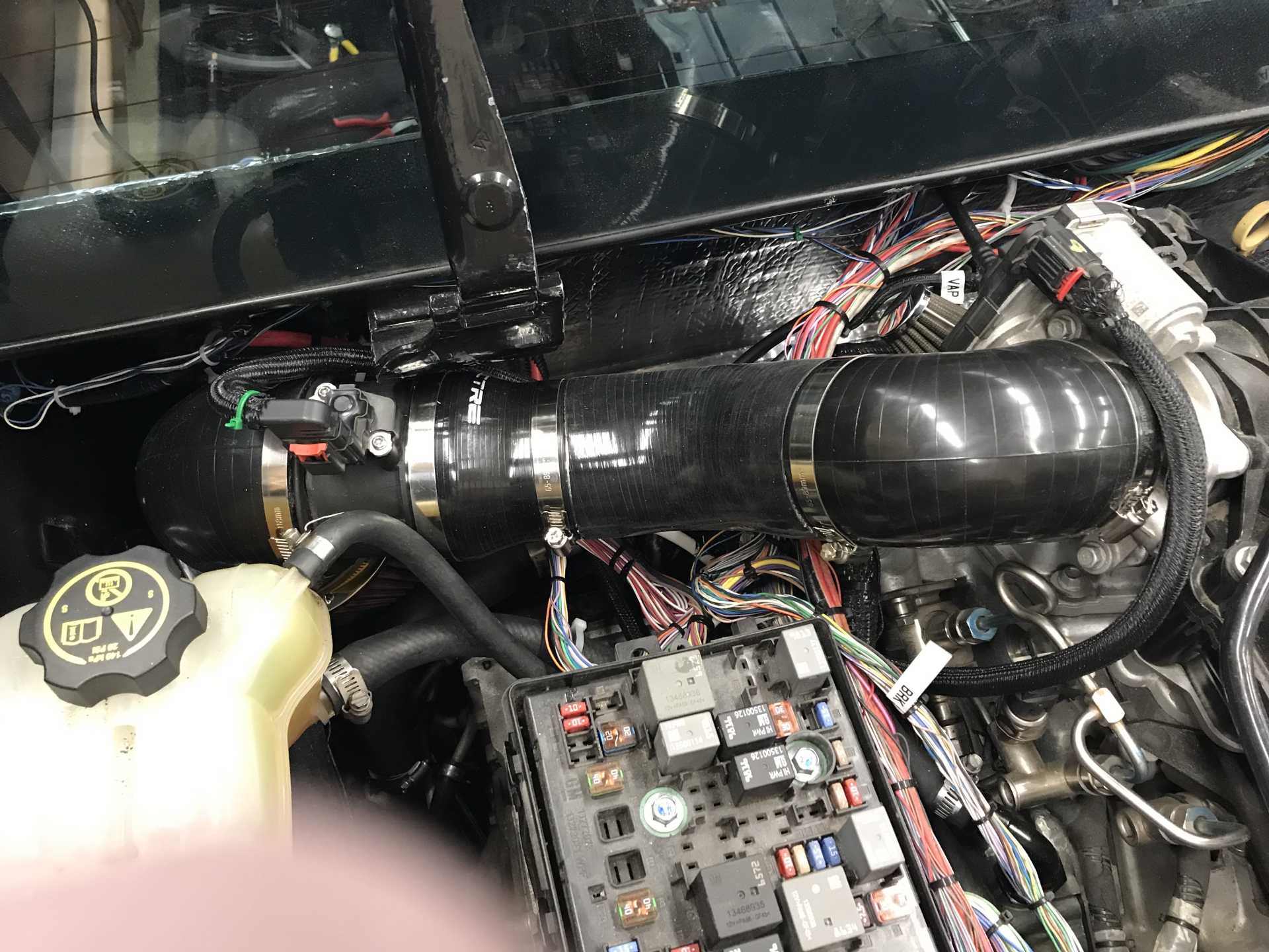
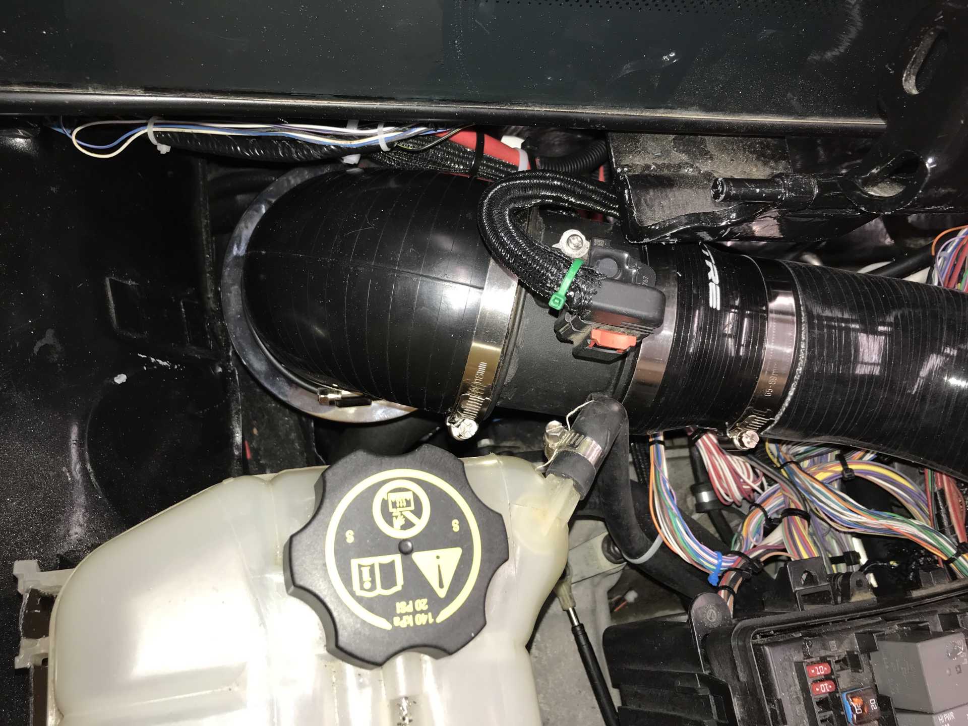
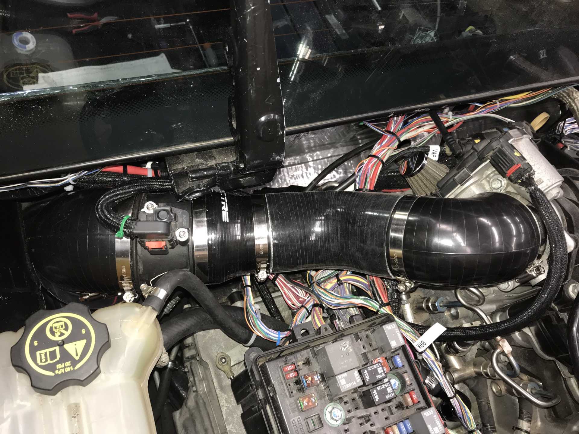
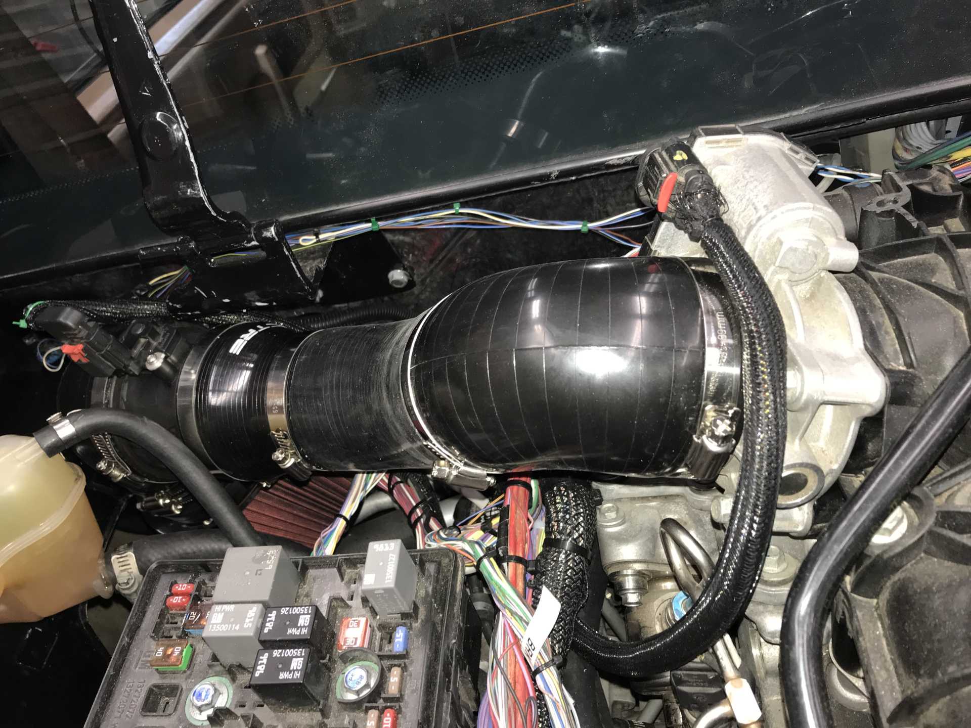
The throttle body on the Impala sticks up and is a concern that it might not clear the trunk lid. An imprecise measurement shows it may fit. Next week I'll put the lid in place with a lump of play dough on top of the TB and close it. If it does close this will tell me how much room there really is (the play dough is between two layers of plastic wrap to prevent a mess). Bought some ABS plastic fittings in 2" size (since I already have 2" pipe) and prototyped the routing and clearances of the air inlet pipe. I'm ordering a 6" long cone filter and elbows to match up to the MAF (3.7" dia) and the TB (3.0"). I'll probably use a little 3" exhaust metal pipe to make joints between the different parts since I'll paint it if needed; real air inlet pipe is stupid expensive. Like everything else the fitting will be tight. The Fiero motto should be "No space unfilled".
I'll figure out what I did to the cruise control switch too, since it stopped working. Probably hooked it up to the wrong wire.
Here is a video of starting it up, just use this link and select slow download. It will take a while to download.
https://rapidgator.net/file...nking.it.up.MOV.html
Added a Youtube link here too
https://youtu.be/Reb_1LrIV5c[This message has been edited by MikesFirstFiero (edited 10-23-2021).]
|
|
|
|
La fiera
|
OCT 22, 10:45 PM
|
|
|
That's a lot of work to fit the LFX into a Fiero! But you did an awesome job! Looking forward to the numbers!
|
|
|
|
MikesFirstFiero
|
OCT 23, 09:38 PM
|
|
|
|
|