Another option would be switching to the 88 rear uprights (you need to mod the cradle anyway). I think they place the mounting of the strut 1/4" or higher than the 84-87's which might be enough and they angle the struts in further which might gain you the needed frame rail clearance as well. I am sure between Blooze and your drawings, you can confirm how much of a difference there is between the two.
The reason I think there is a difference is I ran the same wheels/tires on an 86 and 88 and the 88 had slightly more vertical clearance between the lower spring perch on the strut and the tire. However, if you are running 17" wheels, there isn't enough clearance (shy about 1/4") for a 17" wheel to pass over the strut mounting tabs on the strut when attached to the 88 rear upright.
Thanks again Fieroguru. I had considered going completely with 88 suspension but never took the idea too far. In the back, I am running 18" wheels.
I added the camber plate to my drawing and I think I am getting close. I may have to still drop the spring a little more and sacrifice my strut travel if I can't lower the entire strut relative to the spindle. I will probably have to shorten the threaded end of the strut rod too as its going to be very close to the 355 rear deck height.
Here is a picture showing the strut and camber plate position in relation to the stock strut tower.
Here are a couple pictures showing the top of the strut in relation to the proposed 355 Rear deck. I clearly have a little more fine tuning to get it all to fit just right. There is also the matter of the 355 rear quarters having a bulge on top that actually forms the base for the coupe body work . On the 355 spider, it will form a well for the soft top to be stored so I may have to liberate some of that space for my strut camber plate. See the last photo.
Edit: to add last picture for reference
[This message has been edited by Yarmouth Fiero (edited 09-28-2014).]
Remember that you will be adding in a 1" or so adaptor to the join between the strut and the hub to get the 4" width increase where your strut only went out 3" tops. This will push the strut lower end inward by that 1" which then gives you more room between the axle boot and the bottom of the strut. You can then even possibly lower the strut down maybe a 1/2" or so to get a bit more travel and still clear the boot. If you add the spacer in on your drawing, you should be able to see the interference possibilities with the new location.
Thanks Don. That was my plan to use the spacer at the spindle although now that I have the strut drawn exactly as I purchased, my 3D model is showing me enough clearance between the strut and the upper frame rail. I think because of the offset on my wheels, perhaps the suspension will only move outward 3 1/2" even though my track increase is 4". Does this make sense?
[This message has been edited by Yarmouth Fiero (edited 09-29-2014).]
It will be interesting to see how everything actually comes together on the car. You will be very close on your upper strut placement to have the clearance under the rear clip as well. That strut really is quite a bit longer on the top that the oem?
I am planning to stop by and see Blooz on Wednesday to get some measurements of the rear clip. I may even bring his original rear clip home to use while mocking up my rear suspension. I can see that getting at the camber plate is going to be a nightmare once the body work is fitted for good.
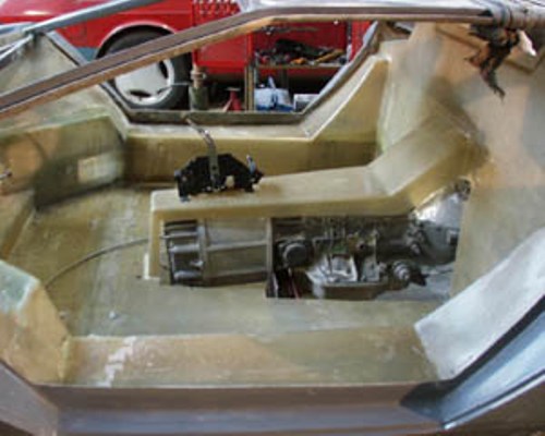
Here are a few pictures of the driverside rear wheel mocked up at the desired track width with the strut in place. Its going to be very close to the desired strut height once the spring is compressed another 2 1/2". Once I have added the rear quarter body work measurements, I'll have a better idea if the camber plate is going to fit under the body work.
You can mock up your system more easily by removing the springs altogether.
How much space do you have between the top of the tire and the underside of the upper frame rail? I had to notch my upper rail to get the travel I wanted.
I am planning on replacing the springs with the 9 1/2" of 3" dia plastic pipe for mocking up the suspension any further Blooz.
With regard to notching the upper frame rail, I will be doing the same notch as you since our wheel / tire set up is almost identical. There is not enough room at the moment once you factor in the sweep of the suspension and final camber settings. I was going to wait until after I build the new strut towers before notching because at the moment, there is not much holding the rear frames together.
I may run my notch all the way through to the inside edge of the upper frame rail just to ensure I have clearance for the strut when things start bouncing around.
[This message has been edited by Yarmouth Fiero (edited 09-29-2014).]
Now you're truly neck-deep into the nitty-gritty... the heavy duty stuff that only real custom fabricators attempt and pull off. How does it feel to be sailing uncharted waters?
You're asking a former marine engineer and now shipbuilder what its like in uncharted waters? I don't know anything else but uncharted waters
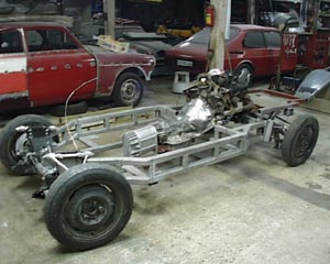
To be honest, I'll be glad when the design work is done and I can start putting metal back on the chassis. The scrap pile is almost as big as the chassis itself now.
My other shop this morning.
It will eventually be another one of these.
[This message has been edited by Yarmouth Fiero (edited 09-30-2014).]
I decided to take an evening away from the rear suspension and bolt my brake rotors together. I purchased the bolt kit from Wilwood which are 1/4 - 28 and they recommend a torque of 85 in-lbs with lubrication. The bolts are 316 stainless steel and the rotor hats are aluminum so I decided to use Tef Gel which is a product we use alot of in the shipbuilding world when using stainless steel fasteners on aluminum vessels. It's a lubricant, anti galling/ antiseize compound that also reduces corrosion between dissimilar metals.
I torqued in two stages using a diagonal pattern and then proceeded to lock the bolts together as recommended by Wilwood. They recommend using 0.032" stainless steel locking wire which I happen to have on hand.
I stopped by to visit Blooz this week and he loaned me a proper set of wire twisting pliers and they worked amazing to produce a nice tight even twist. I definitely have to invest in a pair of these.
When it was all done, it turned out pretty good and it certainly adds a sophisticated look to the brake rotors. Shame it will all be facing inside where it can't be seen.
Thanks Blooz. And thanks for the use of the pliers. They are very easy to use. There is a new Snap-On truck that comes to the yard once a week. I may have to start a shopping list of odd yet interesting tools to add to my shop.
Still thinking a longitudinal SBC with Porsche / Audi gearbox installation and throwing ideas on the screen. Here is a belt drive using 62mm wide Gates Poly Chain GT Carbon belts rated at 325 hp at 5500 rpm. Gates has an amazing belt drive design program that allows you to enter a wide variety of design constraints and it offers suggestions for parts from their extensive catalogue.
It's an interesting concept, but I don't think it will work.
In order to keep tension on the belt, you'd need to solidly mount the belt gears to the chassis through bearing blocks as you've sort of shown. But that would leave a rigid stub shaft from the gear to the inboard half of the outer CV joint. By doing so, the outboard half of the outer CV joint (attached to the wheel) would be rendered a single, straight pivot point. It can't work that way since the axle shaft has to change not only in angle and length, but in height too.
To make the design work, you'd need to move the two CV joints onto a single shaft connected to the wheel and have the drive belt connected directly to the transmission output at one end, and the inboard half of the inner CV joint at the other end. Does that make sense?
It makes perfect sense Blooz. What I am looking at is having the stubs fitted with a tri-pot on the gearbox end and the driven gear end with a CV joint at the wheel. This should allow the engine/ gear to rock on soft mounts and the output shaft to act as the usual drive shaft. Its going to be short so I still have to look at the range of motion. Also, as you can see I don't have a real gearbox drawn so it may be narrower than I have it, allowing for longer shafts. At this point, its just a conceptual drawing so I can run it through the first iteration and see if I can transmit that much power at max rpm. There are many things to consider and refine for sure.
Here is the suggested belt for that hp and rpm. The version I am looking at is 62mm wide.
Edit: for additional info.
[This message has been edited by Yarmouth Fiero (edited 10-09-2014).]
Having read your comment again Blooz, perhaps having the drive belt assembly fastened to the engine/ gear mounts and let it all move as one unit and then have a traditional drive shaft with CV and tripot as the output shaft to the wheels. It would eliminate the input shaft completely and get the whole assembly tucked up close to the gearbox. I found a nice 3D model of an Audi gearbox but the drawing is a little too expensive for a "what if" design exercise.
Originally posted by Yarmouth Fiero: Having read your comment again Blooz, perhaps having the drive belt assembly fastened to the engine/ gear mounts and let it all move as one unit and then have a traditional drive shaft with CV and tripot as the output shaft to the wheels.
Yes... that's what I tried to explain in my post above. The other thing you'd need to find is a transmission where the output shafts were far back enough to give you the forward room to add the two gears and belt system and still have the axle fall where you want it.
Yes, I agree, there are a number of different gearbox models to choose from. I based my basic drawing on the Audi 016 that Don had sent me. From there it was close to 12" between sheaves and the first iteration gave me 4 1/4" dia sheaves and a 62mm wide belt. It seemed like a good place to start and it was very close to what I needed.
Edit to add. I do have the flexibility to move the engine fwd or aft a little so suit the belt length / location. The first iteration gave me three possible belt/ sheave combinations to handle the load.
[This message has been edited by Yarmouth Fiero (edited 10-09-2014).]
I am surprised that the assembly is so far back? I don't doubt your measuring and placement, it was just a surprise that it was back that far. Is there a way to move the engine froward so that the crank harmonic balancer is up against the firewall area and cut into the firewall? Perhaps, if you are set on an SBC (they are quite large), then staying lateral would be a lot less work and more reliable in the long run..... I just think of the Audi V8 engine man is doing and his setup looks like with the 3" stretch, it would be almost perfect placement.
Interesting design thoughts though. I am looking forward to seeing what you end up in the end.
Cheers Don
Edit: Also as Blooz said, solid mounting the belt drives to the engine/trans setup or to the frame and then having CV joints on both ends of a longer axle shaft would also be a better arrangement in my opinion.
[This message has been edited by 355Fiero (edited 10-09-2014).]
Hi Don, thanks for the input. The engine is back quite a distance for sure. I am not sure if the engine intake can be swapped around although I suspect it can, but just in case, I left room for intake ducting. The belts do come in shorter lengths, infact almost half as short as I have shown. Last night when I was doing this drawing, I just sort of picked a belt and drew it. I'll refine the whole arrangement tonight and post an update as per the suggestions today.
The use of belts to get the drive back to the axles has been done before... I just can't find the picture. The pulleys came off a RWD rear end that was shortened to be just a pumpkin. I am sure it was in a replica of some kind.
Here are some other fun pictures to get the creative juices flowing:
Thanks for the pics Fieroguru. That is certainly an interesting gearbox arrangement. I have seen a belt drive before too but I can't for the life of me find it online. I seem to recall it was a dragster.
I double checked my gearbox dimensions and they are pretty close to the Audi 016. As I mentioned, I can move the engine forward a little more to get it tucked behind the firewall. I just need to find a different style intake. I changed the shafts so that the belt drive is tucked in close to the engine/ gearbox. This will facilitate mounting it all together in some fashion. I then stretched out the drive shafts to make them more functional.
You have a keen eye Grasshopper. I'll probably just get a filter notching kit.
With regard to cradle design, I may end up with a cradle within a cradle. I am going to do more research on SBC intakes and see what is available for reversing the intake. I saw another build that has an intake that sweeps around the distributor. If I can move the engine forward another 4" then I can get down to a 8" center to center belt/ sheave arrangement which I think would be easier to design around. That will save me the cost of the filter notching kit.
What intake were you planning to use? The LT1 has been flipped numerous times and just requires building up the seal flange on the ends, but you will have to run distributor less.
I flipped the upper plenum on a modified Holley Stealth Ram intake (see Trintens SBC/F23 build in the construction zone)... lots of work, but works.
Archie also flipped the upper plenum on a TPI intake and extended the TB mounting point to clear a crab dist.
Interseting find seajai, thanks. There are bits and pieces out there in various articles but I can't find any definitive article that gives details regarding the success or failure of the arrangement. I'll keep working at the desgn and refine the details. I am hopeful at this stage.
I did find some interesting information regarding the ability to reverse the intake manifold on a V8. Its seems the LS1 engine is suitable for the modification.
Edit: to add this photo. A jet boat with the intake manifold reversed.
[This message has been edited by Yarmouth Fiero (edited 10-10-2014).]
It would be interesting to see how much horsepower it would rob to run a belt drive setup like that. Also, I would think the belts would heat up quite a bit pushing a 3000lb car on a long cruise. Maybe a custom case running a transfer chain from a FWD transaxle or even a chain from a 4wd transfer case. It would make for a narrower assembly than a wide belt.
The belts are good for 185 deg F which is pretty hot. I've seen some pretty large belt drive HVAC units and the belts rarely got warm. As far as efficiency, the toothed belts typically achieve operating efficiencies around 98%. As well, the belts are self lubricating unlike chain drives.
I have moved the engine as far forward as possible to suit the shortest belt quoted by the design program at 8.66" center to center. Definitely going to have to reverse the intake manifold.
[This message has been edited by Yarmouth Fiero (edited 10-10-2014).]
Belt type drive was done in the 70's in a concept kit car called the ZARA ----- There is information out there somewhere on why it didn't work but I'm sure belt technology has improved (Kevlar and steel belting) so it may work today.
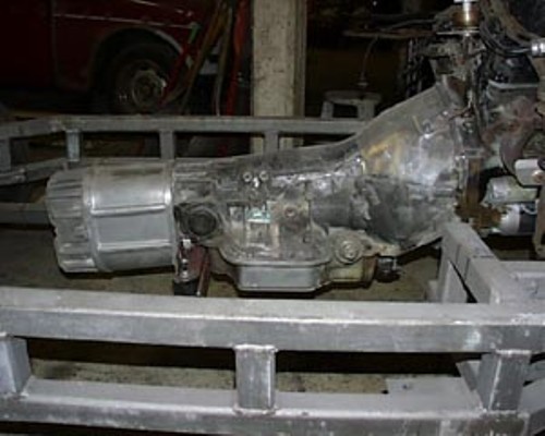
This transmission sounds interesting and the wavetrac differential might help keep the belt loads somewhat balanced. Anyone have experience or an opinion on this setup with regards to my proposed belt drive arrangement?
Taken from the Advanced Automotion website.
01E FWD wide ratio transmission with Wavetrac Differential
This is Audi's version of the 01E front wheel drive transmission. Similar in construction to the quattro transmission but is about 12 inches shorter and 25 pounds lighter. Great for a mid/rear engine kit car, or replacement. Also used in FWD 6 speed conversions like the BHW Passat B5.5.
The mainshaft, first, and second gears are cryo tempered and stress releived. Optional WPC surface treatments are available.
Common Ratios are: 1st 3.50 2nd 1.89 3rd 1.23 4th .87 or .93 5th .68 or .73 6th .56 or .60
Included with this transmission is a wavetrac differential installed and ready to run. The Wavetrac is a patented differential that combines the street manners of a torque biasing differential with the zero traction behavior of a limited slip.
All remanufactured transmission go through quality control program and are fully dyno tested on our custom transmission dynomometer, yielding the most efficient, coolest running, and longest lasting gearbox at the best price available.
Units come with 12 month unlimited mileage limited warranty. Shipping is via truck freight LTL. Freight restrictions prevent us from shipping gearboxes with fluid. Options below are priced only with the transmission.
[This message has been edited by Yarmouth Fiero (edited 10-11-2014).]


 How does it feel to be sailing uncharted waters?