Nice built thread. Good work. I am looking forward to seing it in person some day. Judging by your progress you may have it down on wheels by Aug 12 for the Great Lakes show here in London. It would make a great work in progress attraction.
Nice built thread. Good work. I am looking forward to seing it in person some day. Judging by your progress you may have it down on wheels by Aug 12 for the Great Lakes show here in London. It would make a great work in progress attraction.
I have a new deadline for the show now. It has been a work in progress since I removed the first OE nut 3 years ago after 2 years of driving on the original tires! I don't plan to finish anytime soon, but yes I should have someone to show in August. I bookmarked the SOFA site.
Any estimates as to what the LT1 is putting out? Thats alot more than what I got
------------------ 1986 GT, LT1/4T60E. In the middle of cam/port, new interior, paint and waiting on new wheels. Itll blow you away!! http://hometown.aol.com/ptfiero/index.html build http://dtcc.cz28.com/Customer/LT1Fiero/index.htm
Any estimates as to what the LT1 is putting out? Thats alot more than what I got
Hey Mr. Pat - thanks for looking - how's your cam/port going?
The engine builder Rod from Hot Rod Inc. really seems to know his stuff. Today he showed me timeslips and awards of his own 1973 Nova SBC beating big blocks and running the 1/4 mile in under 9 seconds on 10 inch slicks. I am having him prepare me a build sheet of the rebuild including all parts etc. that I will post on this thread.
I'm not really interested in starting a flame war with anyone since I have no dyno numbers, but Rod claims HP on motor will be in the 350-375HP range up from the stock 260HP.
I am using the smallest jets on the fogger nitrous setup of 100HP - it gives a true extra 100HP at the crank or about 80-85RWHP instantly when the digital window switch hits selected rpm at WOT. Once it is tuned right I may up to a 150HP shot as it is proven that stock LT1 motors can run that regularly without problems. Anything above that up to +300HP would require a digital timing retard box and a second stage to play safe.
With 6.0 Litres, balanced, ported heads, crane cam, 10:1 compression, CAI, and headers, I would be happy with a 90-100 HP gain over stock, which I think is realistic. What do you SBC gurus on the forum think?
Thats more than realistic. What are the specs on the cam? Mine is a pretty beefy cam, wouldnt make for a practical DD, but then, who builds these kinds of cars for a DD? Right now im waiting on the new brake kit to come. The guy keeps blowing me off, and no one wants to move my car because we found out that the bolts holding the rims on are pretty much all broken. Its a wonder it hasnt broken completly. So, I may just end up getting stock replacements so we can move on with the project. Like all my projects, they take what seems like years to start, and a week or 2 to complete. but im actually in the process of discharging from the AF, and hopefully they will let me out. We wont know till JAG tells us.
But a good port job should see about 40-50 crank, and a good cam another possible 100 depending on the cam and tune. I would guess you would be making close to 350-375 at the wheels. 260 is scary!! Let alone close to 400. Im actually going to be terrified to drive mine when its done. Im looking at getting 500 to the ground on the bottle.
------------------ 1986 GT, LT1/4T60E. In the middle of cam/port, new interior, paint and waiting on new wheels. Itll blow you away!! http://hometown.aol.com/ptfiero/index.html build http://dtcc.cz28.com/Customer/LT1Fiero/index.htm
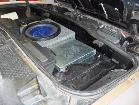
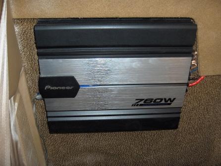
Progress on the weekend was limited to completing the sound system - now I can rock out while I work
Installing a 100amp fuse and 5 Guage wiring from the GM post on the battery, then routed under the car to the distibution block on the firewall:
Wiring remainder of amp - control wire, ground, speaker wires for subs under console, and input wires run separately under door sill to minimize any possible electrical interference:
Power antenna was completed with power/ground obtained in engine bay, while antenna cable and blue control wire run through X-Frame and connected to the deck - a 5' extension cable was required.
Resulting sound through the 4 - 4x10's and 2 10" subs is the best of any car I've ever owned. What I like most is that all components are concealled except the deck that has a removeable faceplate. When you look into the interior it appears stock, that changes when you hear it...
I believe I have achieved my goal of being able to hear it during highway roadster driving with the LT1 growling right behind me Time will tell...
Progress is being made today fitting the assembly on the cradle. I think I may have one of the first LT1's with Archie's auto adapter plate and a Cadillac 4T60 - makes for a very wide setup! I guess Mr. Pat's built with help from Darth would also be wide...
My goal is to try and avoid a notch to the left side frame rail of the car, but a test fit with have to determine that.
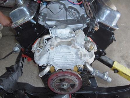
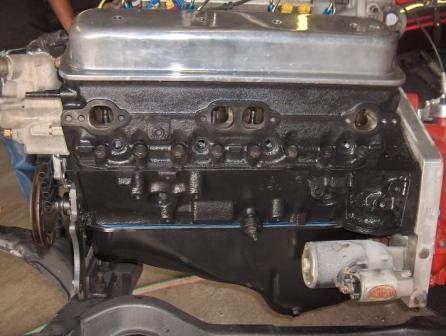
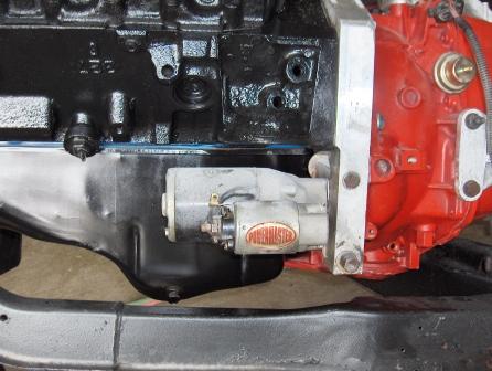
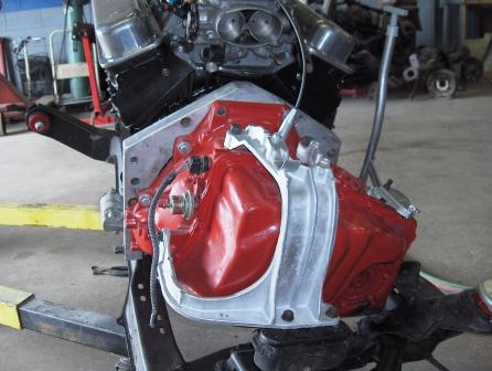
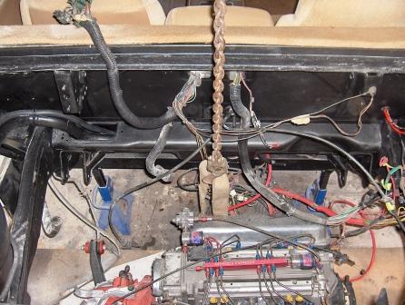
Here is a shot from the front of the motor (passenger side of car) showing Archie's pulley shimmed to tightly fit the Optispark. I had to change the waterpump last year and now is the time to remove the unused lower right port and plug it properly. I am also planning to install a bleeder in the gooseneck as I had a hard time bleeding the system after the stock one was removed to make more clearance at the stock tower. You might notice the water jackets that lead to the throttle body has also been removed and the EGR has been blocked off - (it passed it's final E-Test without it by testing the car as a hot rod) . . . A chrome hugger header will be installed on this side (front of the car) so it stays tight to the block and passes between the cradle (K-frame) and the block. I just noticed I need another knock sensor as my Street and Performance ECM requires two. The car doesn't have A/C so Archie's mount won't be needed. . . . Here is a good shot of the starter mounted - unfortunately it will need to be removed for the oil filter adapter, but you can see how little room there is for clearance there. I also have a new flexplate installed as the first one took a beating while I was learning to properly shim a starter I am hoping that the trans lines are metric fittings - anyone know? Also I will need to run a addtional vacuum line to the intake manifold that the stock trans didn't require - no problem as I've got 2 extra ports. . . . This is a view from the driver's side showing the mount location. I may need to modify the mount / bracket etc. for clearance as it is much larger that the TH125c bracket - the good news is that it's also stronger...
Fiero2m8
[This message has been edited by Fiero2m8 (edited 06-26-2006).]
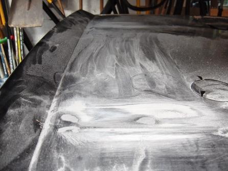
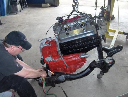
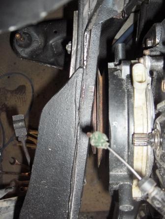
Here's a picture of Rod making a VERY small notch in the cradle to clear the pan near the rear control arm mount. It was required to sit the whole assembly level. Please note the motor is sitting on the higher mount location on Archie's front engine bracket. Also enjoy Rod's various safety violations while using a cutting torch
I had previously modified the rear hugger header for clearance to the governor but since this trans is 2" longer there and the governor cap is higher, I decided to add a 3/8" spacer at the header gasket for clearance rather than changing the angle of the header since it would require the rest of the exhaust to be tweaked. Also required is a trans to engine mount to be fabricated since neither of the stock ones I have will work without modification. I also notice that although the throttle body is now closer to the TV and throttle cables, it may be tricky connecting them since they are 180 degrees off - anyone have pictures of the best way to route them?
Can you tell I'm excited and can see a light at the end of the tunnel after 4 months of waiting in order to get a better deal on the price? Ryan
Did you by any chance tell Archie what tranny you were using when you ordered it? He apparently has a skinnier version of the adapter plate for the 4T series trans. Wish I had of known beforehand. Would have made things alot easier.
Did you by any chance tell Archie what tranny you were using when you ordered it? He apparently has a skinnier version of the adapter plate for the 4T series trans. Wish I had of known beforehand. Would have made things alot easier.
When I was doing the swap orginally I was using the TH125c, so it didn't come up in conversation. I stopped by the shop this afternoon to see the assembly mounted level in the cradle, so the hard part is done. I also have an axle to fit the drivers side, so it's probably to late to change it now, but a thinner adapter plate would be nice - maybe next time. Good info for others comtemplating our swaps though!!!
[This message has been edited by Fiero2m8 (edited 06-26-2006).]
here are some pics of the oil adapter i made from a chunk of aluminum and a "hollow bolt" from the sunfire oil adapter set up. The hollow bolt allows me to swing the hoses in any direction.
lol it dosn't leak.. I started to remove it after 6 years of trouble free operation to replace the O-rings and just as I started to remove it I thought I should get some pics..
------------------ GT just waiting for the conversion
84 Fiero Turbo Vortec 4300 Phantom GT L35 block, Syclone Intake and ECM with Moates adapter 50lb injectors, 3 bar map sens, T04B Turbo
www.cardomain.com/id/vortecfiero Murphy's Constant Matter will be damaged in direct proportion to its value Murphy's Law of Thermodynamics Things get worse under pressure. Arthur C. Clarke "Any significantly advanced technology is indistinguishable from magic"
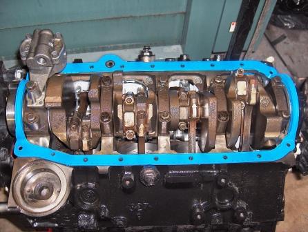
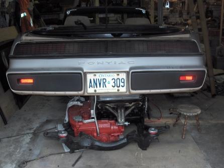
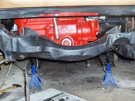
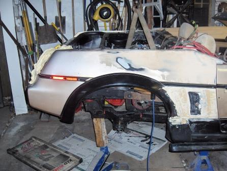
Well I finally got the cradle assembly home the other day and it took 4 guys to carry it from the back of my truck to slide it under the rear of the fiero. Here is a picture of it:
I spent that night test fitting the cradle and I am happy to report that there are no major issues.
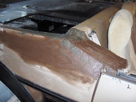
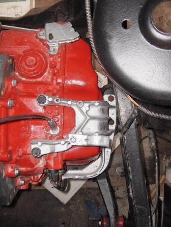
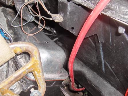
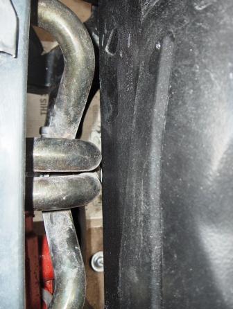
The left side frame rail clearance was far more that I was expecting, here are some shots of the clearance:
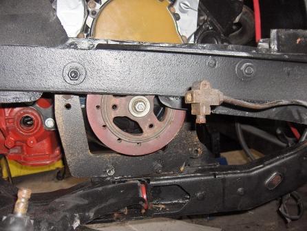
During the test fit, I realized that I needed to switch to the lower bolt holes on Archie's front engine mount to level the assembly and gain better access to the crank bolt as shown in these pictures:
Other clearances were as follows...
Front valve cover to hinge box:
Rear valve cover to passenger strut tower:
V-belt balancer to passenger frame rail:
Rear header clearance after spacer added:
Transmission to engine block:
Now it is time to bolt the cradle's poly mounts into the frame:
Last pictures before I join the boys to head down to the U.S. Grand Prix at Indy. (We rented a 2006 30' RV for the trip and are sitting in section "J" Sunday...)
Cradle is bolted in - it took a while to line up the rear mounts after the front ones were in loose, so being patient and sober is the key
Still needs alot of dressing up and cleaning but you get the idea here. Next week I hope to spend a few evenings doing the axles, hoes, wiring etc...
Sorry for not commenting sooner after calling for updates I'm just getting back to really read the forum after two weeks away. Been a few hectic weeks for me also.
Your project continues to amaze me. You're going along so well - awesome stuff. I'm jealous
Thanks guys for your support - it helps motivate me to get out to the garage... My PIP doesn't seem to be working right now, so I'll try posting a few pics tomorrow.
Ryan; have you tried using myfiero.com for image hosting? Iv'e never been able to get pip to work, even with the help of a friend that is a computer geek.
Getting the axles to fit for a custom swap might be the hardest thing to get right. In my opinion, the best way is to do some research first to understand how they go together and what you need. From there you can start a cross reference search etc. to get a plan of attack to minimize trial and error.
As some reading next I went to the local wreckers to get axle cross reference info I was interested in since Fiero's are rare in the boneyard around here. I was interested in a few things:
1. What other cars came with the same RIGHT axle as a Manual Trans 85-88 Fiero? 2. What other cars came with the same RIGHT axle as a Automatic Trans 85-88 Fiero? 3. What other cars came with the same L/R axles as the 90 Cadillac Seville my 4T60 was from?
Below are the answers for the benefit of the forum:
1. Fiero '85-88 axle; MT, R. also came on:
6000 '87 Front axle; 4" BC (100mm), MT (5 spd), R. 6000 '88 Front axle; 4" BC (100mm), MT (5 spd), R., early Celebrity '87 Front axle; 4" BC (100mm), MT (5 spd), R. Celebrity '88 Front axle; 4" BC (100mm), MT (5 spd), R., early
2. Fiero '85-88 axle; AT, R. also came on:
6000 '85 Front axle; 4" BC (100mm), 3 spd, R., 6-260 (4.3L, diesel) 6000 '85-86 Front axle; 4" BC (100mm), 3 spd, R., 6-173 (2.8L) 6000 '87 Front axle; 4" BC (100mm), AT, 3 spd, R., 6-173 (2.8L) 6000 '89 Front axle; 4" BC (100mm), 3 spd, R., 4-151 (2.5L) Celebrity '85 Front axle; 4" BC (100mm), AT, 3 spd, R., 6-260 (4.3L, diesel) Celebrity '85-87 Front axle; 4" BC (100mm), AT, 3 spd, R., 6-173 (2.8L) Celebrity '89 Front axle; 4" BC (100mm), 3 spd, R., 4-151 (2.5L) Century '87 Front axle; 4" BC (100mm), AT, 3 spd, R., 6-173 (2.8L) Century '89 Front axle; 4" BC (100mm), 3 spd, R., 4-151 (2.5L) Ciera '87 Front axle; 4" BC (100mm), AT, 3 spd, R., 6-173 (2.8L) Ciera '89 Front axle; 4" BC (100mm), 3 spd, R., 4-151 (2.5L) Citation '85 Front axle; AT, R., 6-173 (2.8L) Skylark '85 Front axle; AT, 6 cyl, R., late
3. Seville '89-90 Front axle; w/o ABS; R. also came on:
Eldorado '89-90 Front axle; w/o ABS; R.
The answers to #3 were slim!
Murphy's law applied here as none of these #3 axles were available in the Niagara region. I thought, no problem, I already have 4T60 axles housings I previously upgraded to fit the old TH125c, so why would I need Cadillac parts....wrong
Here is the difference between the TH125c axle housings and the larger 4T60's:
I swapped the 4T60 bearings onto the stock automatic axles for the upgrade - here you can see they fit the larger housings only now:
The main reason I went to all the trouble to do this was so I could continue to use the Fiero or 6000 with light duty brakes etc. CV joints shown here with retaining c-clip and axle removed:
However, when I went to plug the drivers side axle in the trans, oops! The splined shaft was too large for the normal 4T60 axle housing - I needed to get a Caddy one The wreckers only had two 90 Devilles in the back field, but I was lucky that one of the two had the axle housings I needed - here they are:
Unfortunately there were also two different sizes! The drivers side required a larger boot with 1/2" notches, while the passenger side used 3/4" notches in the boot! I think that the larger drivers side one was to accomodate the short axle clearance and/or handle additional torque. I trip to Automotive Warehouse for to new 90' Seville inner boots solved that - here they are:
The next hurdle was the rear hubs: The right rear one had some spline damage from a previous axle life lesson so I grabbed one at the wreckers off a 94 Grand AM with 5x100mm pattern shown here:
Unfortunately it didn't quite fit, so off to Crappy Tire (aka Canadian Tire) for some new ones. Amazingly they had a pair in stock! Here they are:
I also bought some new CV bands and asked to borrow the free loaner tool for them, but it was still MIA. Next I found out that they can't get CV grease anymore, so I bought the last four tubes they had. Looks like I will once again be using trusty dull side cutters and hammer to get the CV bands on tight
The last thing I did in prep to assemble and install the axles was to re-install the struts and hardware at the top. Don't worry the struts and hardware will be painted up pretty after an alignment.
O.K. here is the build up and installation of the axles - I'll start with the passenger (right) side.
For my setup, I had done a rough calculation and "in theory" I believe that I should be able to use a stock Fiero right axle for the passenger side. (Fiero axles have Archie's guarantee not to break using his kit during normal driving... ) Since I had moved the engine assembly roughly 1.5 inches left of stock and the 4T60 right axle seal was approx 2" longer than the TH125c trans - I concluded the axle should be within 1/2 inch of the ideal position in the tripot.
Lets see if I'm right...
Since it is critical that the axles don't bottom out when the suspension is under load, I decided to do a test fit without CV boots. That way I could measure and inspect the axle's habits and position throughout the suspension travel range.
Here is a shot of the axle installed without boots and the suspension unloaded:
The CV joint and new hub:
Overhead shot:
At this time I realized that my engine assembly is no longer completely square in the cradle! I had decided not to move Archie's front mount mainly because it was already bolted and welded in the perfect left/right spot. However with the 4T60 trans being larger, we were limited on how far back the trans could go before hitting the rear of the cradle. If I had to do it over I would try moving Archie's front mount a 1/2 inch closer to the firewall for overhead appearance improvement. There is plenty of clearance at the front header to do this. However when I looked at the most important shorter than stock drivers side axle, I noticed that this slight angle was perfectly square to the hub. It happens to be in an ideal location over there so I'm not going to move the engine mount at this time. If I did, it would place the drivers side axle housing behind the hub (probably the stock location).
O.K. back on topic, next I installed the tie-rod and did an eyeball alignment for now (slight toe-in) and bolted them up. Remember, these are the ones I had shortened 2 inches and flipped the mounts around two inches to the outside of the car. Hopefully this will reduce bumpsteer on the car that is now lowered 1.5 coils.
Next, I set up the jack in order to simulate loading the suspension:
Using a tape measure and a coat hanger with a 90 degree bend on the end, I marked the clearance between the bearings and bottomed out on the hanger:
Then I measured the distance between the transcribed marks, results were:
Total depth of axle housing 4" Axle too long minimum clearance 1.5" Axle too short minimum clearance 1.0"
Success!
The axle stays near the middle of the axle housing throughout it's suspension travel range
Driver's side axle should go right in, as it was previously modified to fit the LT1/TH125c swap. At that time I shortened the stock axle by approx 3/4" and reversed it to gain additional clearance. Here is a shot of the axle reassembled with the Cadillac tripots and boot already on - notice only 1/2" of axle between boots rather than the stock length of 1.5":
I wasn't able to use both c-clips on the tripot bearing end, so I flipped it over (again to shorten the overall length) and cold welded the splines to lock in the bearing to the axle in place of the retaining clip. This method isn't ideal, but I didn't want to weld and apply heat for fear of weaking the heat treated axle. This method did work for 12 months previously without failure, so I am using it again.
Here is a shot of it installed. Once again I used the jack to measure overall clearance. On this side the minimum clearance is only 1/2" from bottoming out but it never gets closer than that throughout the suspension travel:
I was a little concerned that when the axle is completely unloaded the angle is a little sharp downward and might increase wear on the outer CV boot. This car doesn't pick rear tires off the ground like an 84 VW GTI did, but I am considering adding a rear sway bar to minimize the potential for unnecessary excessive body roll with the additional weight back there. If anyone has installed a 22mm bar on the rear of their Fiero please post pictures showing the mounting locations. I would also appreciate opinions / experiences of how the rear sway bar effects the cars balance and handling.
Below are some shots of the completed axle installation as seen from above and behind the engine compartment:
Hopefully I'm getting towards the less messy and more fun jobs on this project...if wiring is considered fun
Thanks, Ryan & Fiero2m8
[This message has been edited by Fiero2m8 (edited 07-07-2006).]
Most of the work tonight was cleaning up the garage, but I did install the factory LT1 water pump and prepped Archie's alternator bracket for reassembly:
Added a bleeder on the gooseneck and will be plugging an unused port on the front this time around:
Can't remember why I paint the bracket last time:
Used a wire brush on a cordless drill to bring the aluminum back:
Planning to work on hoses tomorrow using Winston's diagram to help with my memory:
Check out www.FieroLT1.com for more great details on the LT1. It certainly helped me out last year when I first installed the motor!
I've decided to switch from NGK TR55 plugs to new NGK TR6 (one step colder) for the nitrous application:
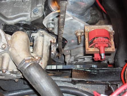
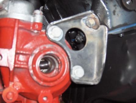
I had to tap the tension bolt hole in the head and used two fender washers for alignment purposes. I am using the MSD Blaster coil that will be mounted here:
Just need to pick up a new belt before tightening everything up.
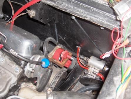
I picked up the next belt 1/2" x 38" long. After slipping it on Idiscovered a new way to install and tension it by yourself with a pry bar between the alternator and A/C portion of front motor mount without having to jack the car up or work from underneath! I didn't even have to hold the pry bar, just wedged in a crescent wrench while I tightened the alternator bracket with a socket set:
All the coolant hoses are installed and just need to be tidied up and secured properly before the wheelwell liner goes back in:
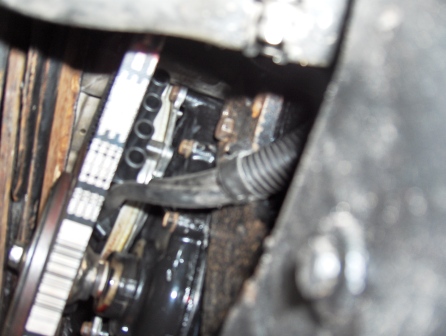
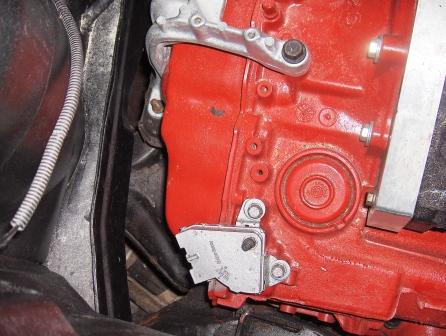
My LT1 has a vented Optispark, and since the intake in now on the other side of the car, I chose to run the line to an extra filter I had:
Here is a shot from underneath the Optispark - 1 vacuum line goes to the intake and the other to the filter to draw air through it and help keep it moisture free:
Next, I reinstalled the the existing Fiero fuel lines and new filter. I had to extend the lines with new ones along the trunk wall to the regulator that is now on the passenger side due to the reversed intake:
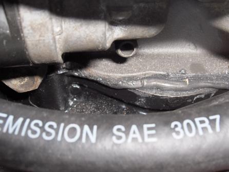
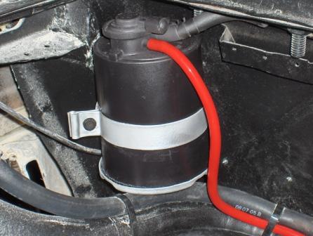
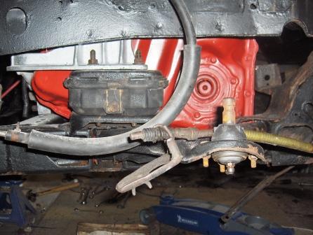
The new brake booster filter was installed well away from the stock location that was very close to the front header:
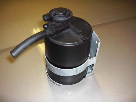
I was pleased with how the EVAP cansister came out using Tremclad Flat Black and Aluminum Wheel paint for the bracket:
Vacuum lines are next and are currently a work in progress...Only question I have on them so far is:
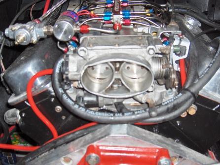
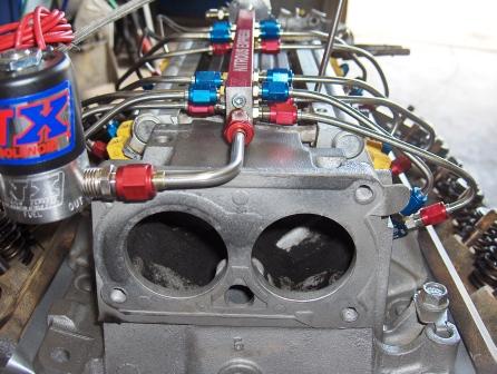
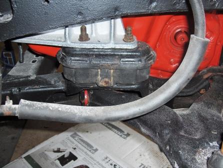
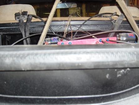
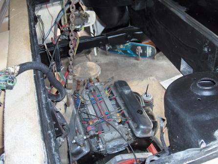
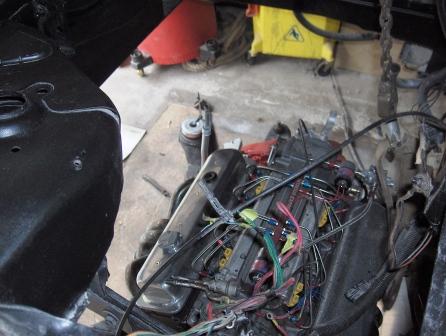
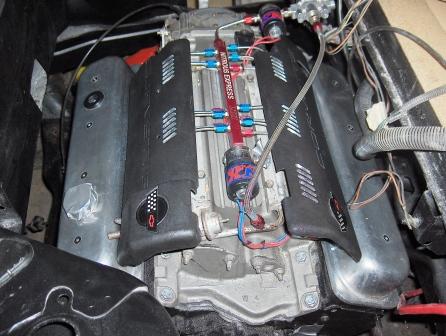
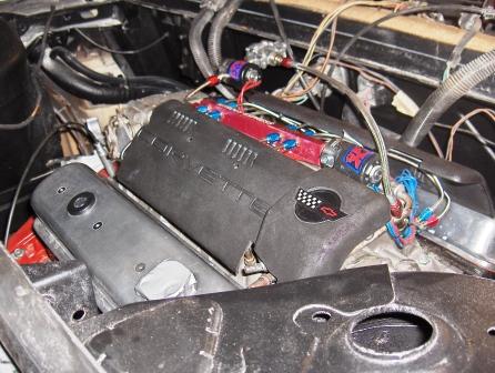
I have a PCV valve installed in the intake but I also have an opening on the rear valve cover. Where should I run lines from these items to or do I need both etc? See picture below of PCV location in center of intake and vent location in valve cover:
Surely I don't need two but don't want to create a vacuum leak either. Any suggestions would be appreciated as my memories good, but short
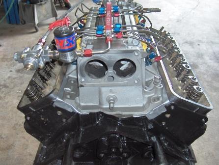
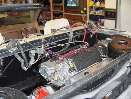
The LT1 intake has been reversed - cutting and welding my orginal 1994 intake didn't work out so good, so this 1996 intake is going to be used.
Fiero2m8
Can you explain a little more about the "cutting & welding that didn't work....."? Any mods to the '96 intake? or, just lots of RTV to seal the ends? Thanks! Harry
Vacuum lines are next and are currently a work in progress...Only question I have on them so far is:
I have a PCV valve installed in the intake but I also have an opening on the rear valve cover. Where should I run lines from these items to or do I need both etc? See picture below of PCV location in center of intake and vent location in valve cover:
Surely I don't need two but don't want to create a vacuum leak either. Any suggestions would be appreciated as my memories good, but short
Thanks, Ryan & Fiero2m8
Yes you need two... and don't call me surely :-)... The pcv valve gets hooked up to the port in the center under the throtle body.. ( this draws air from the crankcase to the intake vacum) The line from the rear valve cover is hooked to the large port on the side of the throtle body.. (This is a port to the air filter side of the throtle plates... it is the "in" for air to the crankcase...) Hope this helps... Chuck btw... you are going to find that the line you pluged on the water pump.. (the line that goes nowhere in Wiston's pic) is REALY needed....
Yes you need two... and don't call me surely :-)... The pcv valve gets hooked up to the port in the center under the throtle body.. ( this draws air from the crankcase to the intake vacum) The line from the rear valve cover is hooked to the large port on the side of the throtle body.. (This is a port to the air filter side of the throtle plates... it is the "in" for air to the crankcase...) Hope this helps... Chuck btw... you are going to find that the line you pluged on the water pump.. (the line that goes nowhere in Wiston's pic) is REALY needed....
Hi Chuck,
Thanks for confirming what I researched and jogged my memory on this morning. I searched and found out that the top TB port is an air passage and have since connected a line to the valve cover. When I was taking a couple pics tonight, I found the port under the TB and it jogged my memory that it went to the PCV.
I'm a little confused on the water pump port, maybe you can elaborate. My theory is this: When I bought the LT1, there was no port in that location on the water pump that came on my motor. I have since replaced the Optispark and waterpump and the replacement pump did have that port that I never used last year. This time around I also omitted the "Tee" in Winston's diagram as I am not using the TB coolant lines or the water jacket steam tubes.
It sounds like you are using it on your setup - where does it go?
Can you explain a little more about the "cutting & welding that didn't work....."? Any mods to the '96 intake? or, just lots of RTV to seal the ends? Thanks! Harry
The 1994 intake was sent out to a third party for welding and I never got it back. They provided the 1996 intake at no charge. Rod did have to grind a spot on the front of the block that would have caused a problem, but otherwise it just has a good amount of adhesive silicone on there. He did mention that the two intakes were not completely identical, however the 1996 intake in still not symetrical as shown in these pictures:
Now, on with the show (I went to the drive-in Friday night)
I cleaned up my K&N filter and after it dries, I will re-oil it red before installation:
My CAI design uses the stock elbow with the IAT in it and approx 18" of 3" stainless steel boiler venting I had. The flexible end of the elbow will allow me to angle the stainless towards the driver's side air scoop where the K&N filter will reside just in front of the wheelwell liner:
All the vacuum lines are finished, so my next posts will be on the Throttle cable / TV cable setup and then the shifter cable that will probably have to be "CUSTOM".
"Custom" seems to be my new favourite word on this project
I can't believe that I haven't seen this thread before today.
Great job, and excellent write-up! I can't wait to see it finished.
Me either - welcome to the thread, I'll try my best to answer any ?'s you have along the way. I have a goal to have it running by my birthday this month, so stay tuned...
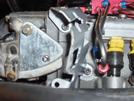
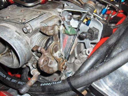
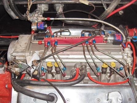
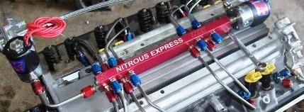
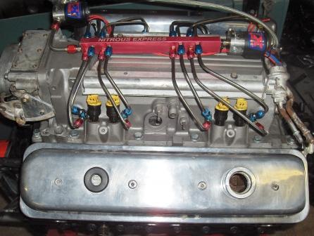
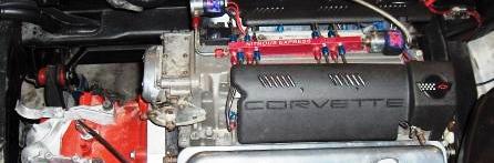
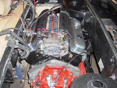
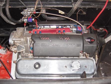
Here is the throttle setup. It normally would have been straight forward, but the design of the Nitrous express rail and the fact I wanted to reuse my Corvette fuel rail covers made it tricky. The TV cable adapter from Street and Performance is attached to the stock Throttle Body (TB). http://www.hotrodlane.cc/ The stainless nitrous lines and nozzle interferred with the throttle bracket, so I modified it to sit closer to the TB as shown here:
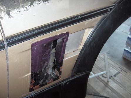
The only problem I ran into was I couldn't get WOT - it turned out to be a problem under the gas pedal. I had to remove insulation under the carpet in that area on the firewall and now it's good:
The TV cable needed to be shortened and then I fully depressed the throttle to allow it to set itself to the proper position. I still need to hook up the WOT switch for the Nitrous Kit but I will do that later.
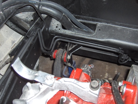
The vacuum lines are in place. Top left port on TB to rear valve cover. Middle left port to EVAP canister. Bottom left and right capped throttle body antifreeze/coolant passage. Center vacuum port on intake below TB to PCV valve on side of intake:
The largest port on the side of the intake is for the brake booster. I also have two red vacuum lines on this side, one for the fuel regulator and the other is new for the vacuum modulator on the transmission. The other side of the intake uses one port to draw air from the Optispark, and the other is capped for future use if necessary.


 I believe that I should be able to use a stock Fiero right axle for the passenger side. (Fiero axles have Archie's guarantee not to break using his kit during normal driving...