Originally posted by Russ544: CHRF supplied the clutch, pressure plate and custom flywheel. they all look great. the disk is a dual friction style with Kevlar pucks on one side and full organic on the other.
I guess this worked OK for you? AIUI, the T5, which they are accustomed to serving, has a different spline than the 282...
Alan asked me what spline I needed at the time I ordered the clutch. otherwise it's the same one they use on the sand rails. (Fiero is 1"-14 spline)
I am working through a potential small issue with the clutch as it relates to the Isuzu trans however. After looking at a couple stock clutches I have laying around It appears that the V-6 clutches have a slightly larger diameter contact area for the throwout bearing. the bearing for the Isuzu trans sits very near the tip of the fingers. I had been under the impression that all Fiero clutches were the same, with only the throwout bearing height differing, but I'm finding this to be untrue. When I've had time to research this more I'll report what I find. It may work fine as it is, but I need to convince myself that it's all as it should be.
[This message has been edited by Russ544 (edited 06-21-2005).]
The stock front manifold will serve duty in it's new Fiero home and provide a spot for the O2 sensor (only one is needed with the Holly computer that I plan to use).
Awesome work! Did I understand correctly that you will use a stock manifold in the front and the header you built in the trunk side?
Awesome work! Did I understand correctly that you will use a stock manifold in the front and the header you built in the trunk side?
Yes. Although the front manifold looks like a cast piece in the pics it's actually a fabricated "tube" header with runner diameters similar to the 1 5/8" ones I built for the rear.
One last wrap up on this clutch package before moving on. The clutch is installed, for the duration this time, and seems to be working perfectly. the "clocking" of the release arm seems to be just about ideal, allowing just a tick over 1" of travel at the slave pushrod, which should be just right for this trans setup. I did run into one puzzling situation with the flywheel as it was just too thick to allow for clutch engagement. I have no doubt whatever that Alan (CHRF) would have had it taken care of for me, but it was no big deal to just have it faced off myself. In order to actually match the stock Fiero 4 banger specs, about .210 would have to be removed from the face but I preferred to leave a few thou of a shoulder for the ring gear to seat against so I had .200 taken off instead. apparently none of the other flywheels CHRF has sold for Fiero use have had this issue, so we assume it's just an Isuzu thing. One other "Isuzu thing" is that the throwout bearing has a smaller thrust surface diameter than the Muncie or Getrag, so it sits very close to the tip of the clutch fingers. This doesn't seem to be a problem with a few hundred SBC swaps however, so hopefully it won't be a problem for the N* either.
So now I get to some real fun. wiring . I layed the Holly/CHRF harness out on the engine today to see how it fits. everything looks great... so naturally I need to change it all . I don't intend to use the Cad decorative cover so I want to hide as much wiring and hoses as possible. the design of the intake manifold should allow for most of the wiring to be hidden under it, so tomorrow I'll be pulling it off and beginning the cut and splice project. I had hoped that the used Fiero engine harness I bought from a forum member would show up today, but it seems to be my normal luck for parts to show up on the Monday after the weekend I needed them, so this time should be no different. I'm sure I can find something to do in the meantime. The Holly harness makes the engine run, but the Fiero harness is still needed to monitor/control things like oil pressure and temp guages, charging and starting systems, etc.
[This message has been edited by Russ544 (edited 06-24-2005).]
I gota give a big thumbs up to Fierosforever here. I purchased a stock 88 engine wire harness from him recently and he must have sent it out the same day he received my payment. I received it today. Seems like some other forum members aren't very.... uhhhh "punctual" when it comes to shipping parts. so Thanks John !
I find wiring to be a very tedious process. I'm always afraid I'll cut the wrong wire so I check and double or triple check each and every wire before it gets cut and tossed in the dumpster. Some wires may not be needed for their original function but can perform another duty in the system so careful planning is helpful. Lots of wires hit the floor today, but tomorrow I'll be combining what's left of the stock harness with the Holly/CHRF harness so it will get beefed up again soon. The items that remain from the Fiero harness are: temp gauge sender, oil pres sender, speedo plug, bu light plug, starter wireing and alt wiring, Several ground and hot wires that will tie in to the other harness are retained as well. All the original Fiero computer wiring, plugs and ecm have hit the floor.
[This message has been edited by Russ544 (edited 06-27-2005).]
Anyone who follows me down this road is in for a bumpy ride, cause I don't have a clue where I'm going LOL . I do intend to put in a little more detail on this part as this is the part that worries most people (myself included). but be aware that I expect I'll make a few mistakes here and may have to do some backtracking.
Wheeew. what a long tedious day in the land of N. The wiring isn't proving to be particularly difficult..... just time consuming. I realized this morning that I didn't need the Fiero fuel pump relay as one is incorporated into the CHRF harness along with it's own fuse, so a couple more changes were made to the Fiero harness right off the bat. The tan/wht wire gets cut as it enters the Fiero relay to be joined up with the grn/blk wire from the Holly harness. In order to retain the fuel pump backup function of the oil pressure switch the two or/wht wires at the Fiero relay are cut and joined together. The old ground wire at the Fiero relay is no longer needed and can be removed completely. This is what the Fiero harness looked like after the "excess" wires were removed.
Next I layed out the harness on the engine and began "fitting" it to the N* . virtually every wire needed some alteration. after that phase it looked like this. note that the portion of the harness that ends up inside the cabin (bottom of pic) isn't visible in this photo, but is in the lower right 1/4 of the pic above.
Once the Fiero portion of the harness was done, the CHRF portion was layed out on the engine along with the modified Fiero harness so they can be blended together. I removed much of the wire loom that came on the CHRF harness so the two harnesses can be packaged together, and to access the individual wires that I wanted to alter in order to route them in a more hidden fashion. note that a number of wires are being routed under the manifold. I figure at least one more full day just to finish up the engine wiring, but it's coming along.
I was able to get good compression from the #8 cyl by spiking the valves. it took over a month for a friend to ship a fibre scope to us to try out. the fibre scope was pretty inconclusive. no obvious big damage but you can tell that by rotating the engine and it is smooth. i am on my way to autozone now to borrow a harmonic balancer puller so i can remove the front engine cover and release the tension on the timing chain tensioner. the plan is to run the engine and see how bad the smoke is. if it is not too bad I will continure to run the engine and see if it gets better or worse.
Wireing is essentially done. I see now why you seldom see any detailed writeups on wireing. it's such a tedious and time consuming project that by the time you get a days work done you've forgotten what wire you cut and spiced to which wire earlier that morning . Granted, it ain't running yet, but it wasn't really as bad as I had feared. As I mentioned before, many of the wires are run under the manifold to clean up the top side, and I'm pretty happy with the way it came out in that regard.
I am looking forward to using more basic tools again like hammers saws and welders however .... that stuff I understand
Russ
[This message has been edited by Russ544 (edited 07-10-2005).]
With all the computer controled devices on the stock Cad you'd think there would be a plethera of sensor holes in the block, but the truth is there aren't even enough to go around, in a Fiero swap anyway. a place to poke the temp guage sender is the stumper, but as the throttle body heat was going in the dumpster anyway, a table opened up just in time for lunch. I wasn't inclined to pull the water log off just to drill and tap the hole out to the 3/8" pipe thread required for the sender, so a shop vac was attached to the water inlet in order to suck the chips out, and away from the water pump.
In the spirit of keeping the top of the motor clean, I didn't want to have another hose draped over the runners for the power brake hose, which is on the "wrong" side of the Cad intake, so an alternate route was found. This ought to give the bench racers at the car shows something to scratch their head over LOL
For those not familiar with the N*, what I've done here is to utilise what was once the EGR passage through the water manifold to get the power brake vacume to it's destination. EGR is not supported with the Holly computer anyway so the EGR valve and all it's related hoses were tossed. The PB hose will attach to the filter on top of the water pump belt cover. also circled above is the old EGR port into the valve body, which I ran the 3/8" pipe tap into so it can be plugged. the sensor circled is the water temp unit mentioned above.
[This message has been edited by Russ544 (edited 07-10-2005).]
Originally posted by Russ544: In the spirit of keeping the top of the motor clean, I didn't want to have another hose draped over the runners for the power brake hose, which is on the "wrong" side of the Cad intake, so an alternate route was found. This ought to give the bench racers at the car shows something to scratch their head over LOL
For those not familiar with the N*, what I've done here is to utilise what was once the EGR passage through the water manifold to get the power brake vacume to it's destination. EGR is not supported with the Holly computer anyway so the EGR valve and all it's related hoses were tossed. The PB hose will attach to the filter on top of the water pump belt cover. also circled above is the old EGR port into the valve body, which I ran the 3/8" pipe tap into so it can be plugged. the sensor circled is the water temp unit mentioned above.
Dude, that's a sweeet idea. I like your harness routing, too.
Thanks Will. I've been thinking about moving the coil pac to the area in front of the burp valve, between the valve covers. that would kind of cover the mass of wires where they all come together there. I'm just not sure if the decklid would close if it was mounted that high.
Thanks Will. I've been thinking about moving the coil pac to the area in front of the burp valve, between the valve covers. that would kind of cover the mass of wires where they all come together there. I'm just not sure if the decklid would close if it was mounted that high.
One thing you CAN do is move the coil pack to the left about 4". There are two sets of mounts and it looks like you're using the right hand set. If you use the left hand set, you won't have to do as much cutting of the dogbone bracket on the chassis and you'll have better access to the PCV grommet (for installing new oil).
One thing you CAN do is move the coil pack to the left about 4". There are two sets of mounts and it looks like you're using the right hand set. If you use the left hand set, you won't have to do as much cutting of the dogbone bracket on the chassis and you'll have better access to the PCV grommet (for installing new oil).
Actually it is mounted in the left holes now. I think I'll get a valve cover from CHRF to make it look a little nicer on the "show me" side, but the new cover won't have the mount holes for the coil pack. It will have to be moved somewhere, but I may have to wait until it goes in the car to finalize the location.
Maybe you, or anyone out there, can give me some ideas on the evap system to use on this swap? I'm thinking of using the Fiero evap canister and plumbing it like the stock Fiero system, but not sure where to get a ported vac signal for that. I haven't really investigated it in depth, but maybe someone has a good solution for this ??????
I used the fiero evap canister and plumbing to the tank. I also hooked up to manifold vacuum. I used the caddy evap solenoid hooked to the caddy ecm to run the thing. I believe there is a prt on the TB that is not used which is for port vacuum.it is on the top side but is covered buy the rubber gromet that has the intake vacuum port.
brief update: I got the water lines hooked up today out to the underbody tubes. I robbed some underbody pipes off a parts car and used three pieces welded together to form a crossover pipe. they are retained by utilizing the clamps from the Fiero pipes. one half of the clamp was welded on the crossmember, along with a hook to retain the other 1/2 of the stock retainer on one side of the pipe which is then bolted on to clamp it down. worked great. A visit to my friendly auto parts stores hose room netted some hoses with appropriate bends and one elbow that also reduces the water pump line from 1 1/2" to the crossover pipes 1 1/4". Some of the hoses are actually original Fiero parts .
[This message has been edited by Russ544 (edited 07-16-2005).]
I don't know what's wrong with those Cadilac engineers. It seems like everything is on the wrong side of these engines. heck even the engine was in the wrong end of the car. dumb. sure make it hard to get it all fixed the right way . Wile at the hose room today I picked up a U-turn 3/4" hose, intending to use it on the other side of the manifold to get around the throwout arm and to get it pointed in the "correct" dirrection. it fit better here however, so I'll look tomorrow for a tighter radius for the other side. The hard line came with my N* in a box of parts, so I'm not actually sure what it was for but it fits here perfectly and had the necessary bead around each end to retain the hoses and is bent in just the right places to shoot under the shift cable plate.
[This message has been edited by Russ544 (edited 07-16-2005).]
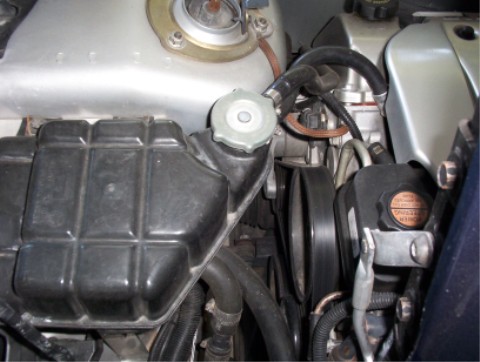
I did a little homework today on how the cooling system works on the Cad, and how that would best be incorporated into the Fiero. What I came up with is to use a surge tank from a C-4 Corvette. the shape and size is about right and I have a friend who says he has one on a parts car. the one shown is on my own 92, but all C-4s seem to have the same tank.
The highest points in the system need to be bleed of any air pockets by attaching a line to them and routing it to the lower port on the neck of the surge tank where it can be purged into a low mounted coolant recovery tank via the upper port on the surge tank. Water is circulated through the surge tank at all times as it gets plumbed in line with the heater hose system. As I showed earlier, I enlarged the port near the radiator hose neck to accept a temp sender, thus eliminating the original purge port, so a new vent needed to be made in that area. One of the bolts that holds on the bracket on top of the neck is screwed into a blind hole, but by drilling it on through into the water passage below it and tapping the hole for 10MM threads (note shop vac to extract chips), the old vent fitting can now be installed here.
Purging the high point of the radiator itself will be experimental, as I plan to install a cap on the radiator and run a line from the overflow port all the way back to the surge tank purge line. the pressure cap will be on the surge tank itself and both the surge tank and overflow recovery tank will be located in the engine bay.
It's too hot to work any more today (103*). I need beer
[This message has been edited by Russ544 (edited 07-17-2005).]
Hello there! I am new to the forum and have been following all of your posts Russ. I would also like to have a 4.3L V6 installed into my 86 GT. I live in Vancouver Wa and do not have the ability to install it myself so it will have to be done by a local mechanic. That is unless you do installs :-) It wont be right away, as the engine thats in the car runs so well, I want to get some miles out of it before the swap. The information you post is much appreciated.
[This message has been edited by Jolcon (edited 07-21-2005).]
Originally posted by Russ544: It's too hot to work any more today (103*). I need beer
roger that statement!
i spent 7 hours replacing the motor mounts on my 86 fiero... (one of the mounts needed a little mod.) in 105+ degree temps. there was not enough beer...
Hello there! I am new to the forum and have been following all of your posts Russ. I would also like to have a 4.3L V6 installed into my 86 GT. I live in Vancouver Wa and do not have the ability to install it myself so it will have to be done by a local mechanic. That is unless you do installs :-) It wont be right away, as the engine thats in the car runs so well, I want to get some miles out of it before the swap. The information you post is much appreciated.
It's always good to hear when people get some usefull information out of my build threads. It's my hope that a few people who wouldn't have attempted a project will reconcider after seeing someone else doing it, and ultimatly be able to enjoy some of what I enjoy, in the process of creation. I do understand how some folks just don't have the tools, ability or even the desire to do major projects however. Unfortunatly I can't seem to find the time to even get all my own projects compleated, so I don't take on outside work. Perhaps smeone here will see this and be able to help you when the time comes for your swap.
Glad you replied Russ. One thing that would be helpful is if you could maybe list things the mechanic will need to know when he starts to install the 4.3
I can gather some info from your previous posts. I see where you changed your mnd about mounting the water pump upside down. I probably dont need a walkthru, but things he will run into, where a decision has to be made, may be helpful since you have already done this project.
I do have some questions though, like:
Should I ditch the stock automatic tranny and get the isuzu manual one? What year of engine do I want and from what vehicle? What kind of carb do I need? And where can I get the wiring harness info? Should I buy the Archie's kit for the builder to use? And how much beer is it going to cost me for all this info?
Oh! Yeah! And next time you are in Vancouver Wa, can you give me a ride in your 4.3 Fiero?
[This message has been edited by Jolcon (edited 07-21-2005).]
Should I ditch the stock automatic tranny and get the isuzu manual one? What year of engine do I want and from what vehicle? What kind of carb do I need? And where can I get the wiring harness info? Should I buy the Archie's kit for the builder to use? And how much beer is it going to cost me for all this info?
Oh! Yeah! And next time you are in Vancouver Wa, can you give me a ride in your 4.3 Fiero?
If you want a ride in the 4.3 IMSA you'll have to get here pretty soon as it's getting very close to giving up it's place in the engine bay for the N* . I bought a Formula pretty cheep a wile back that should provide a home for it someday, but I have lots of other projects in line before that one gets it's turn. I do think you'll be pleasantly surprised at the power of the 4.3 if you warm it up a little. it's a very very nice package for the Fiero IMHO. To answer your specific questions: The tranny is a point of personal preference. personally I think all hot rods should have a clutch.
The carb I'm currently using is an Edelbrock 500 . it works great for my setup with the moderate cam etc.
I'll let you know when I have my quota of beer. just keep it coming
Russ
EDIT PS: The stock Chev HEI is a computer controled unit which needs to be modified for non computer use. There's a local guy here in SW Or that does the conversion on it for like $50.oo or $60.oo . let me know when the time comes and I'll hook you up with him or drop your dist off to him for you.
[This message has been edited by Russ544 (edited 07-22-2005).]
I noticed in your write up, that you did not mention anything about the AC. I dont ever use mine but thought I'd ask since it looked in the photo like the alternator was where the ac unit on the 2.8 would be.
I noticed in your write up, that you did not mention anything about the AC. I dont ever use mine but thought I'd ask since it looked in the photo like the alternator was where the ac unit on the 2.8 would be.
For anyone curious what I look like just look in the dictionary under "idiot". As a Corvette owner one learns to expect to get the shaft at the parts stores, so when I needed a surge tank for the N* project I first called a friend of mine who has a vette parts car. at first he said he had one, but then discovered it wasn't any good so I went to what I assumed would be the next best source.... my usual wreaking yard. they did a serarch and finally came up with one across the country for $80.00 . I choked a bit as I said "order it", believing it would be 3 times that much from my local Chev dealer. well today I went by the dealer to check on the price of an overflow tank, cause I wanted a brand new one of those. when he told me it was only $11.00 for a brand new Vette overflow tank I just about fell off the stool (and so did he actually) so I asked how much the surge tank was............................... $46.oo . &$#@*% .
I did a little homework today on how the cooling system works on the Cad, and how that would best be incorporated into the Fiero. What I came up with is to use a surge tank from a C-4 Corvette. the shape and size is about right and I have a friend who says he has one on a parts car. the one shown is on my own 92, but all C-4s seem to have the same tank.
The highest points in the system need to be bleed of any air pockets by attaching a line to them and routing it to the lower port on the neck of the surge tank where it can be purged into a low mounted coolant recovery tank via the upper port on the surge tank. Water is circulated through the surge tank at all times as it gets plumbed in line with the heater hose system.
Purging the high point of the radiator itself will be experimental, as I plan to install a cap on the radiator and run a line from the overflow port all the way back to the surge tank purge line. the pressure cap will be on the surge tank itself and both the surge tank and overflow recovery tank will be located in the engine bay.
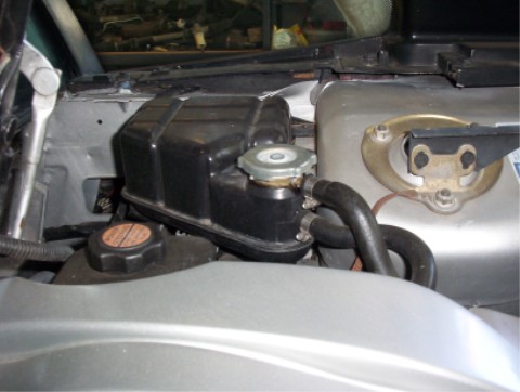
I have the Vette Surge Tank on my S* GT and have run it for over a year. This is how I mounted it.
As far as the vent line on the Rad goes, I dont think you will need it. I have a 20# cap on my Rad and a 16# cap on the VST. The hose barb on the Rad is pluged so no air can get in and I dont have a surge tank in front anymore. ALL of the work is done at the rear cap on the VST. I have run this system in 105+ weather and had no problem. To purge the Rad all you need to do is twist the Rad cap off till coolant comes out then twist it back on. I am not concerned about steem in the Rad because it will condence into coolant as the rad cools. If I get so much steem in the Rad that it causes a problem, then there is a much more serius cooling problem that is causing all that steem.
HEY. how did you steal my idea for the Vette surge tank before _I_ even had it ? you're good
Looks really good Rickady88gt. I assume you have the overflow tank mounted low, over by the trans? did you use the Vette overflow tank on your car as well? I actually plan to put the surge tank on the drivers side, as I plan to put my oil cooler on the right, to take advantage of the IMSAs right side vent. My left side vent is destined to feed cool air to the air cleaner. I'm getting to a point now where I need to actually plug the engine into the car to finalise some of these details. the space available is shinking, so more carefull planning is needed all the time. BTW: thanks for the tip on the rad vent. I guess I'll use my "optional" plan of installing a petcock in the radiator overflow tube in case I want to check for any air up there. . thanks for the input, Russ
[This message has been edited by Russ544 (edited 07-22-2005).]
I'm using the Holly Comander computer system but the Holly has no provision to operate a vapor canister system the way the Cad ecm did. I wanted to retain the canister, and figured I could operate it the same way the stock Fiero did. unfortunatly the 98 N* throttle body doesn't come with a "ported vacume" port. No big deal,.............. it has one now drill 1/8" hole all the way through, at the max angle possible, into the throttle bore, then drill through the outer housing with a 3/16" drill and 1/2 way through the bore wall itself.
3/16" brake line was used to fab a fitting. it fits snug in the hole but got epoxied in place to seal it just the same
I now have a ported vacume port
[This message has been edited by Russ544 (edited 07-22-2005).]
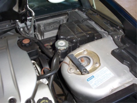
Cool thanks. No I dont have any "overflow tank" per say like the stock Fiero. I only have the Vette Surge Tank and it is mounted as high as posable just over the C500 plug. Infact it is the highest point of the cooling system so the air will go into it and not out of it. It has a constant flow of coolant thru it via the TB heater system. BTW I disabled the TB heater lines so now the TB runs cool. One thing you will need to think about is all the lines that run into and out of it? It has an overflow/vent line, I just ran this one with the stock Vette hose down the front side of the engine. It dose not drip coolant on the engine but dose drip on the exhaust but very rarely. The surge tank has the constant flow "purge" line that is what you drilled and tapped for. And it also has two large hose barbs for cooant to return back to the coolant system. I ran one of them to my T stat housing like the stock Intrigue and the other down to the hose barb that is on the stock Fiero coolant return pipe just above the right hand front cradle bolt. The stock Fiero heater return line that used to go to that hose barb now runs to the stock S* heater return on the engine.


 . I don't intend to use the Cad decorative cover so I want to hide as much wiring and hoses as possible. the design of the intake manifold should allow for most of the wiring to be hidden under it, so tomorrow I'll be pulling it off and beginning the cut and splice project. I had hoped that the used Fiero engine harness I bought from a forum member would show up today, but it seems to be my normal luck for parts to show up on the Monday after the weekend I needed them, so this time should be no different. I'm sure I can find something to do in the meantime. The Holly harness makes the engine run, but the Fiero harness is still needed to monitor/control things like oil pressure and temp guages, charging and starting systems, etc.


 LOL .
LOL .


 but very rarely. The surge tank has the constant flow "purge" line that is what you drilled and tapped for. And it also has two large hose barbs for cooant to return back to the coolant system. I ran one of them to my T stat housing like the stock Intrigue and the other down to the hose barb that is on the stock Fiero coolant return pipe just above the right hand front cradle bolt. The stock Fiero heater return line that used to go to that hose barb now runs to the stock S* heater return on the engine.


