At this point, Im already about half way through this entire swap/build already. But, as it is a build, It is a story. So I will start from the very beginning.
About this project: I swapped the 3.4 DOHC into the car 5-6 years ago. I got the turbo itch, and had the funds. So I purchased some parts, most courtesy of eBay! First I bought a F40 Six speed.
Then I bought a turbo, Garrett GT3582R. With a T3/3" V-band outlet, factory Garrett anti-surge housing. Then I went to Tial for a 50MM blow off valve Again to Tial for their MV-S 38mm V-band waste gate Once more to Tial for their Stainless V-band exhaust housing
About this car: I purchased this car in the June of 2003 in Long Island, NY. It is a Silver 1988 Fiero GT. Fully optioned, with leather and sunroof and a 5 speed. 183,000 miles.
It's been to the 20th Fiero anniversary. I've driven it from the atlantic coast to the pacific coast. The original engine dropped its timing chain, just due to its high mileage. The second engine was a refreshed 86 Fiero 2.8 with a cam. I spun a bearing around a tight turn at max RPM in second, It lost oil pressure momentarily. The oil level was a little low. I did take it to the track for just one quarter mile before it spun the bearing. It ran a 16.3 @ 80.03. I replaced the engine with a 3.4 Pushrod engine 7/4/04 I moved to Las Vegas with the car 02/05.
10/31/06 The 3.4 DOHC Swap begins. I got bored with the pushrod 3.4 and due to a couple issues, I decided it was time to swap it out.
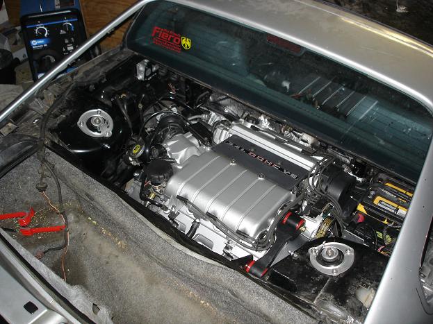
My goal for this swap was to do a complete 94-95 3.4 DOHC swap with factory style routed exhaust, using my cars original (216,000 mile) 282 Getrag. The engine management system was on the 94-95 OBD 1.5 platform. I made some modifications to the program to enable the use of the manual transmission. The code was already there, just needed to be turned on and some values programmed in.
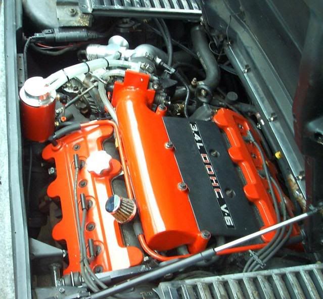
Heres the donor engine/car
To do a 3.4 DOHC Swap, there are a lot of things to be done. You need to: Build an exhaust system Build a fuel delivery system Build a harness Fabricate an upper mount or an alternate method of anchoring the engine against axle torque Clearance the decklid hinge box Clearance the strut tower near the dogbone brace.
More later...
[This message has been edited by Fierobsessed (edited 02-04-2013).]
Guru, you're on the ball! Made that cup some time ago, I just hope that with the major diameter being what it is where it is welded, that I won't have any strength issues. This engine should rather easily turn out 400+ RWHP, as all turbo 3.4 DOHC's have.
Anyway... More detail on the swap itself, keeping in mind this all happened about 6 years ago, long before I decided to turbo,
Building an exhaust system: I chose early on to go Fiero style routing, using two front manifolds, 2.5" 409 grade stainless and a Flowmaster 80 series muffler, which everyone knows on an 88, it will not fit! It needs to be modified. I cut up and patched 3 mufflers before I finally got it right. First attempt (yikes!) Second attempt Third and final attempt Much better! And this is its final configuration Shown with an old muffler
after some cleaning, polishing and painting Exhaust. Done!!
Fuel delivery: I really dont have any pics of what I did. But simply, I scavenged the plastic fuel lines from a 4th gen firebird, and used that to run the fuel to the quick disconnects that were already on the 3.4 DOHC. I also used a 90 TTA fuel pump in the tank. Nothing special or difficult.
Wiring harness: Again, I didn't take any pictures of this process this time. But I can say that It takes me roughly 40 hours to build a harness from the time I have the complete donor harness in hand. Much of the time is spent dissassembling the harness. I always start by stripping all the tape and split loom off, then I de-pin the ECM connectors. Next, I cut all ground and power splices out. At this point the harness just comes completely apart.
All the connectors get plugged into the engine where they are needed, then all wires get routed an taped in to eachother. All wires get shortened and lengthened as needed and the new power and ground splices are made. I reuse the bulkhead passthrough from the Fiero. That thing is a pain in the butt to dissassemble and clean! I then tape and loom the whole harness. Then it is done.
That's my process for harness building. I do need to build a completely different harness for the Turbo build, I will document that process more closely when I get there.
Fabricating an upper mount:
Many 3.4 DOHC owners know that this is risky business. I've never broken my timing cover. I am not afraid I might. I know that the reason theirs broke, is solely because their dogbone applied a strong twisting force on the lifting bracket. I designed mine to only place a straight back pushing force on the lifting bracket.
This is the raw structure piece I built. I chose this shape because It would be low enough profile so that there would be no need, or reason to have to trim the decklid. I welded an 1/8" plate to the top, then using a flap disk cleaned it up, and painted it. The lifting bracket itself was cut up and I welded a sectioned piece of pipe, that the bushings fit into, in place. You can see in this picture the two main mounting points for the bushings, the one on the cam carrier is doing most of the work. It just clears the decklid!
Clearancing the chassis for this engine: This engine CANNOT be mounted without some minor clearancing of non-critical structure. The decklid hinge box
The dogbone brace Tight fit when done!
In the process of the build I also found a need to build a custom fill housing using pieces of an old 2.5L thermostat housing and the 3.4 DOHC's plate. I also discovered why it is important to use the engines original thermostat in this configuration. I had a LOT of trouble getting the Fiero style thermostat to work in this housing. It was too isolated from the engine heat to function at all.
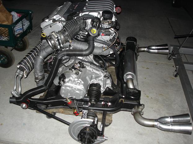
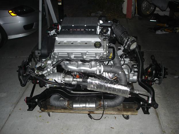
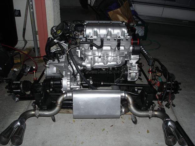
Once all of that nonsense is done, It's time to move on to installation! Heres the 4 sides of the engine package that got loaded into the car.
And as it was for the last 6 years:
That's pretty much it for the original swap.
Upcoming, the problems I had with the engine, and the beginning of the turbo installation!
Before I get into all the nasties about turboing this engine, It's important to know what kind of resources I have in my garage. I am working out of a 3 car garage, that doubles as a personal metal fabrication/prototyping shop. I very recently got the bulk of the large tools.
First up is my mill. It's a relatively cheap benchtop mill, Bolton Tools ZX45. Since it is not a Knee mill, the whole head is able to be raised and lowered as needed (at the expense of my arms). I have a rotary table and a mouting vice and various collets, chucks and endmills.
Second up is my Lathe. Birmingham 12X36 Geared head Gap bed lathe. It's pretty nice, still chinese built, but it seems decent quality. I got the Aloris style quick change tool post and a few other accessories. This is my favorite tool in the garage.
Next is my TIG welder. It's an OLD 1979 Miller Dialarc HF-P. It weighs as much as the mill at around 700 LBS, but it is good for 310 amps, and can weld ANYTHING. I recently found a few problems with it that once corrected made this things welds come out so much better. It's a wonderful piece of equipment! However, Since it's power requirements were so great (100A single phase 240) I decided to tack on a breaker box, with cam-lok feeds and a few auxiliary 240 volt outlets, and a few 120V outlets to the sides of the welder. This way my power comes from a slightly modified breaker box, to my welder, and that feeds power to all my large equipment. So in effect, my shop is mobile.
Slight mod to an extra panel cover
A MIG welder is a fabrication MUST HAVE. This one is a Millermatic DVI. It runs on 120 or 240. uses gas, It's rated to 150 amps, so it can weld some pretty heavy stuff. It comes in the same package as the famous Miller 250/251.
I recently came across a SMOKIN' deal on a blasting cabinet. An elderly gent offered it to me for about 1/4 its price new, and it was still very new. It is a TP Tools 960-SE This was something I've always wanted, but I never though I'd get one like this! It even came with extra glass protectors, gloves, 100 lbs of glass bead... It was a deal I could not pass on!
My girlfriend Dayna wanted to try it out!
Whatcha doin Dayna? Ohh, an Allante Intake. Nice work!
Fortunately, I already had a 60 gallon air compressor. I've always been a fan of the Craftsman compressor. My dad had one for 20 years before the compressor head finally quit. So I figured I'd get the larger unit that used that very same compressor head.
I went cheapo on this piece of great equipment, Straight to harbor freight for a belt sander. I've always needed one of these for fabricating exhaust. I do most of my pipe cutting with a Sawsall, then I flatten the cut surface with this belt sander. The fitup is perfect. I can then TIG weld without any filler in most cases. It comes out beautifully. This belt sander makes that possible.
I also have an engine hoist, an arbor press and plenty of other odds and ends. It's crowded, but capable.
Then there is my little dinky, crowded work table. Having a 3 car garage doesn't offer a heck of a lot of wall space. Especially when things like shelving, Lathes, Mills, Compressors, welders, and Blast cabinets, Jet engines... take up said precious wall space. My dad playing with the TIG for the very first time, on my work table.
Overall, This is my garage/workshop
Oh, and Just incase anyone feels the need to ask, this is another project for another build thread in the future, but It's being worked on a little while this project is going on. So none of that rhetoric about what engine I should have put in my car. Because I'm doing THAT too.
[This message has been edited by Fierobsessed (edited 02-04-2013).]
Guru, you're on the ball! Made that cup some time ago, I just hope that with the major diameter being what it is where it is welded, that I won't have any strength issues. This engine should rather easily turn out 400+ RWHP, as all turbo 3.4 DOHC's have.
I remember when you made it, because I copied the idea. My LS4/F40 has a hybrid tripod for the driver side and I also had one like yours for the passenger side, but it wouldn't clear the LS4 block... so I "had" to use an intermediate shaft.
I didn't really mension it, but I did rebuild this engine. But I've had a 97 crate engine forever that I'm going to put into service, but with the old 94 heads. I need the older heads for compression and for the flipped manifolds. I Could make a plate to adapt a flipped 96-97 front manifold, but then I'd still have 9.7:1 which is a bit much.
[This message has been edited by Fierobsessed (edited 02-04-2013).]
The 3.4 DOHC is a hodge podge of an engine. The bottom end of the 60º the complex addition of DOHC heads that are driven by a chain and a belt. And it leaks. But on the plus side IT FLOWS. And boy does it. No other engine I have ever heard of takes to boost like this engine does. It doubles its horsepower at well under 1 bar of boost.
4 years with this engine, it ran great. Met my performance expectations time and time again. 26 MPG city (when driven like a wuss) normally 22 MPG City. 31 MPG highway with ease. But I did have some troubles. The engine had a ratteling noise, I never figured out what it was, I'm guessing its the timing chain tensioner. And it also ticked a lot when the oil was at the end of its life and I was ragging on it hard. I also needed to run 10W-30 as 5W-30 made the engine tick like crazy. Thicker oil was always better in this engine. And I chose synthetic. This may have been the single biggest mistake I made with this engine. It seems, that synthetic oil eats seals. The aluminum/silicone lined gaskets that sealed the heads to the cam carriers failed completely. I had oil coming out from everywhere. It appeared that the synthetic oil swelled the seals so much that they blew out. This is what prompted me to pull the car out of service to do the big upgrades, and I'll stay clear of the synthetic this time.
My 282 Getrag was also getting old, It had seen 247,000 miles of service, the last 30K with the 3.4 DOHC. It still works, but it tends to get a little noisy on long steep climbs at highway speeds. I figured it was time to put it to rest.
It looks really good and I envy your toy (tool) collection. As a note to others intending to do a high output turbo motor with aspirations to exceed 400 hp, I would do a 3" exhaust start to finish except for dual outlets from the muffler. I had a tremendous obstruction to exh flow that I was not aware of although I suspected a little. I have a 3" pipe from the turbo that terminates into dual 2.25" inlet baffled 4" round mufflers. I also installed an electric cutout at the junction to bypass those mufflers. With the cutout closed boost pressure reached the 7 psi wastegate setting, upon opening the cutout I discovered it was actually being limited to 7 psi as boost pressure climbed another 3 psi by 5000 rpm with the cutout open. The exhaust note is too loud to run without a muffled option. That 3.4 will run higher rpm than what I'm cammed for and I don't see it needing any less flow than what my pushrod motor needs so keep that in mind.
Originally posted by Joseph Upson: I had a tremendous obstruction to exh flow that I was not aware of although I suspected a little ... I don't see it needing any less flow than what my pushrod motor needs so keep that in mind.
I absolutely agree. It's something I'm a bit worried about. At this moment in time my intention is to go 3" from the turbo outlet, throuh a 3" stock located catalytic converter, to the very same muffler I have been running all along, with the dual 2.25" outlet pipes. But I'm concerned about the muffler's ability to handle all that airflow, then the 2.25" outlet pipes ability to do the same. This engine already runs 2.25" straight out of the manifolds! My other condsideration, is that 100% of the exaust gets crammed to about a 1.25" circle within the turbo before it starts to funnel into the turbine itself. After that, a 3" outlet is like a playground. I bet that the catalytic converter itself is a bigger restriction then the muffler. But for the reason of sanity, I'm going to have a V-band flange connecting the muffler, so I can change it out later if I need to. Or, test without!
Right after Thanksgiving this year, I got my car through inspection, and registered for another year of service, drove it home then the engine came out. I remember the engine being a lot cleaner when it went in, but I'm not overly concerned about that at this juncture. Now for the fun stuff. Where do I put the turbo?
I thought long and hard about turbo placement. Since I wanted the exhaust to go forward first to a stock location cat, I knew that I would most likely have to go with something like this:
This is where the test fitting trials began. Right away I started by removing the old crossover tube, coolant neck, water bypass and fuel lines. This bought me some room to play with fitment, knowing that every thing I removed for test fitting will later need to be modified to work around the turbo system.
Next, I unbolted the 282 Getrag, and permanantly retired it from its very long life as my Fiero transmission. Perhaps It'll get a little rebuild and live on? I think it will! But I am done with 282's. I've moved on.
I removed the clutch, which much to my surpise was in absolutely perfect condition. The original machining on the fywheel, and pressure plate appeared untouched by the clutch for 30,000 miles. The clutch disk itself also was in this rather miraculous exactly as it was when I installed it condition. There was practically no dust in the bellhousing. Nice and clean. I can't say enough how pleased I was with this Clutchnet Kevlar Sprung disk. I highly reccomend this clutch!!!
I bolted up the F40 to the engine to see how I would do the shifter cables, and how that was going to effect my turbo placement and immediatly got to fabricating... For shifter cables, I chose to use the one stock Select Cable like everyone else, and for the shift cable I had California Push-Pull make me the very same cable people have been getting for the F23 swap. This is my now, not so secret weapon!
For these brackets, I used some 1/8" X 2" flat stock, and a piece of 1/8" plate cut and drilled to match the bolt pattern around the shift mechanism. I made 3, 5/8" spacers to raise the plate up a little to clear a few things. Just some quick tack welds to start. I'll finish the welds much later.
I knew that since the turbo will go directly above the shift cables, that I wanted to make the shift cable bracket double as a turbo support, so I made the plate extra big in case I wanted to weld something to it later.
When I'm fabricating things, I always like to take stock on what are the Knowns, and the Unknowns. This way, I can keep working on the Knowns. And think about the Unknowns as I go, or put them off completely untill all the knowns are completed. I KNOW Im going to use an F40 Transmission. I KNOW that the shifter cables need to go where they have to. I also know that the turbo will be above the transmission. So this dictated what my work priorities were. It never makes sense to dive right into the unknowns, when you havn't even factored all the knowns in yet. You'll get yourself stuck when you realize... Oh, crap, this had to go here! And that there is no avoiding it, and that might mean starting from scratch.
So once the Shift cable bracket was completed, it was time to load the engine and transmission into the car for a test fit. A few things that I was looking for: 1. Will the transmission fit in the car with the engine placement as it was with the getrag? 2. Do I need to change the engine location? 3. Does the new shifter cable bracket interfere with anything? 4. Will the turbo fit at all? 5. What about the inevetible addition of an intercooler? 6. How will I plumb this nightmare?
Test fit. Ok so this is roughly where the turbo will need to go. It looks like fitment isn't too bad!
I had a box of 2.5" charge pipe bends that I accidentally ordered a few years ago for a project, (that required 3" pipes) and I kept them knowing that I would most likely need them for my Fiero. I immediatly realized that the turbo compressor outlet could never face straight up, or route rearwards without hitting the strut tower and the decklid. I found that the U bend, with a 90 degree silicone coupler was the magic trick I was looking for to get the compressed air towards someplace useful, It curved right around the shift cables, and down through that spot just above the main frame rail, at the bottom of the strut tower. like this:
The other discovery was that I had to do a hard 90 out of the throttle body to avoid the decklid and run over the top of the air filter, then downwards by the trunk. My plumbing plan was starting to take some shape.
Sure, why not, that looks like a good spot. Easy acces to manifold vacuum too!
So with this picture, I found that I would need to make a sharp, over 90 bend to clear the firewall. I ordered a couple stainless 3" 180's and a super tight 90.
For me, cutting the trunk wasn't going to be an option I would entertain for this project. I figured I'd find a way to avoid that. So Now that I had my ideas on plumbing, I needed to find an appropriate intercooler. Naturally with the mid engine design, and the space requirements, I gravitated towards a Water to Air type. And the best placement I could find for it... Between the passenger side axle, and the cradle. I'll need to do some obvious heat shielding with this arrangement. But I think it'll work great!
Once I had the exact tubo location figured out in that test fit, I pulled the engine back out and made a bracket to support the turbo in that spot. I added it to the shift cable bracket.
You can see that clearly the head to cam carrier gasket was leaking in this picture too.
This is the intercooler I wound up getting in a package deal with a pump and a front mount heat exchanger.
I spent a lot of time trying out various mounting positions for it.
In the end I found that it was just a little too thick to fit between the axle and the sway bar and with fittings, just a little too long to fit between the alternator and the transmission. So I picked up a smaller version of that intercooler.
The engine went back in again this time to play with the new intercooler and to build the down pipe. I started by welding the tight 90 to the V band flange, then welded a second piece to it to make it go slightly past 90 degrees. I needed it to clear the AC lines and the heat shield. Then a third piece to correct to the nearly straight down Looks like I hit the nail on the head with this pipe.
Great build. Watching it closely. Have you tried placing the intercooler in place of the 180* bend after the compressor? That's where mine fit the best.
Thanks! The shifter cables would have interfered with the intercooler I'm pretty sure. As it is they go right through the 180.
You might try mounting the intercooler along the frame rail on the front side of the transmission with the inlet/outlet pointing up.
I have slightly more room there due to my engine/transmission placement being further to the rear (needed for idler/firewall clearance on the LS4), but there is still quite a bit of space there and it would be further away from some heat sources.
If you get creative, you could probably mount it in front of the wheel well on the driver side and route the charge pipes through the fuel fill opening in the side panel.
Another option if you want to do some more fabrication... shorten the intake runners on the upper intake and then take the intercooler and cut off the outlet housing/taper. Add a 2"- 4" open plenum between the intercooler core and the start of the intake manifold runners and then weld it all up. The throttle body would need to be on the inlet of the intercooler, but the volume between it and the ports would be very close to stock.
Here is a shortened intake, just needs the intercooler housing welded off the backside of it (covering the valve covers):
That thought did cross my mind, about an intergrated upper intake manifold/intercooler. I have a 96-97 intake that I could have modified to do that with. Maybe I'll still make something to that effect later on.
Either way, I started welding up my charge pipes last week. And heres the result: Post intercooler pipe welded
Pre intercooler pipe welded
The Blow Off Valve added
Honestly, I was a bit out of practice with aluminum, towards the end they started looking like I knew what I was doing
As far as I'm concerned, the Intercooler is done. My only remaining tasks with it are to mount it properly, and build what I need to insulate it from the radiant heat of the exhaust. Header wrap, foil lined glass heat tape, and some metal shielding will be my weapons of choice. I've had really good luck with these in the past.
One thing I really like about the AWIC's is that you can cool the core by running the pump and a fan on the front mount. So a little heat from the exhaust isn't going to bother me much.
Next on the list, Transmission mounts!
Previously, I was using Rodney Dickman poly transmission mounts, and his brackets with my old Getrag 282. I am also using his poly engine mount as well. I'm keeping my original dogbone setup, and Rodneys engine mount. For the transmission, The rear mount is going to keep his poly setup, with a custom bracket between the transmission and the mount. This is what I came up with:
I made it out of 1/8" steel, it took 6 pieces to make it. It's actually pretty light and very strong. I'm not to worried about this piece!
Then For the front mount, I found that Rodney's mount wasn't compatible with the transmission, there was some interference between the mount and the bosses on the front of the transmission. There was a pretty simple solution to this problem. I removed the polyeurathane mount from the bracket and bolted it straight to the cradle using the factory holes. It's on a little bit of a diagonal, but who cares. Next I fabbed another bracket. For as simple as it looks, its actually as complicated then the rear bracket was, and used 6 pieces of steel as well. Mostly because the bosses on the transmission weren't faced off on the same plane.
One thing I had a problem with in the past, is cracked cradles. The front mount has a tendancy to tear the cradle at the bolt holes. I modified the cradle when I first did the 3.4 DOHC swap to remedy this issue. This is what I did then: That should be plenty sufficient still.
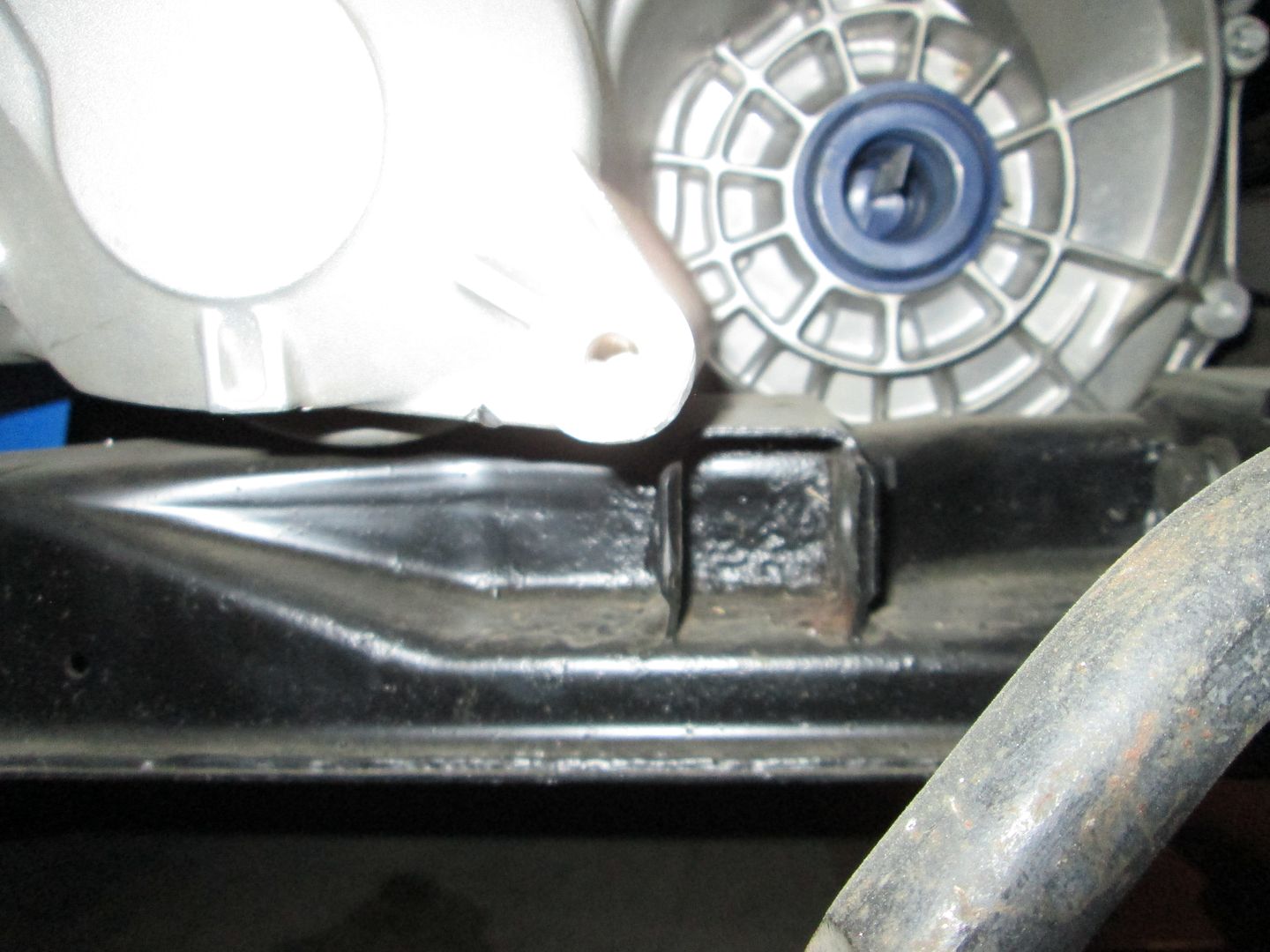
There is an interference between the cradle and the F40 transmission where I needed it to be located. The factory position for the engine to the best of my knowlege places the centerline of the crankshaft 9" above th bottom of the cradle, and 19" from centerline to the rear cradle mounting holes. The interference was located here: This is looking from the drivers side wheel well at the front transmission mount.
With the rear mount in place the transmission was resting in the front on this interference, which is actually about 1/8" above the intended location of the engine and transmission. So some minor clearancing will be needed. I could cut the part off of the transmission, but instead, I will modify the cradle.
And with the transmission mounts done, it is time for yet another test fit. Ok, so this picture makes me a bit giggly.
Bit closer then I intended it to be, but still perfectly fine.
Clears the cradle by 3/8" or so
Clears the frame rail by 1/4" or so
At this point. We are at where this project is at present day. So I'm going to head back to the garage and remove the cradle yet again.
I'm currenly waiting on the various 90's of pipe and other stuff to build the turbo crossover from. I have nothing else to do till those show up.
Fantastic build! I'm really enjoying reading this thread.
I'm surprised that you are still using the 91-95 style intake manifold though, the newer style really flows a lot better. Was it a space concern? Of course, as fieroguru mentioned, you would probably benefit greatly from a custom short runner manifold with this build.
[This message has been edited by Silicoan86 (edited 02-07-2013).]
From experience, clamp your vacuum tube fittings that are subject to boost pressure, the tube to my wastegate came off a couple times but fortunately I didn't over boost the motor. Consider your vent tube size from the valve covers, they were not optimized for boost and can be improved on. If you intend to run double digit boost numbers crank case pressure can build faster than it can be relieved through the stock PCV tubes and at some point lead to seal leaks (a very common character with boosted motors) not to mention possibly force oil into the turbine housing. It will also cause the oil to get dirty quicker.
Not sure what your plans are for oil cooling but one of the best options out there is the sandwich oil cooler found on some VW motors and more appropriately the one I have that comes on some of the 3900 motors. It uses a nipple fitting in place of the block drain plug for coolant flow and a return "T" into a heater hose. I didn't realize it initially but engine oil comes off of the bearings hotter than coolant and at operating temps IS hotter than coolant so you can regulate it with your engine temps and keep it cool and near its most effective viscous range instead of wide temp swings associated with an external cooler. I don't have mine installed yet and my oil temp gauge shows highs of around 240 deg after running the car a little hard with 185 deg coolant temps.
That's a very nice looking turbo so whatever you can do to avoid ever having to take it down to work on it is worth it.
I use the same interlocking GM poly mounts picked up from AZ and at the moment do not use a torque strut so they hold pretty dogone good although a torque strut should be installed for better stability. I didn't reinforce the front cradle mount but had to reinforce the rear cradle mount pad area because it sees the most stress under load and mine actually cracked.
[This message has been edited by Joseph Upson (edited 02-08-2013).]
I have a complete 96-97 Intake manifold set. But for a bunch of reasons I decided against swapping it over.
My main reason is that I really don't care about what my peak HP is, I want a very broad range of high torque levels, something that resembles a superchargers behavior. We can all agree that the more low end torque an engine can produce naturally aspirated, the faster it will spool a turbo. Short runner intakes, or fatter runner intakes have a distinct disadvantage in this field, but make up for it with a more peaky powerband. I want this thing to spool up extremely quick. I probably went one size higher then I needed on the turbo though. That's why I chose to keep the 91-95 intake.
The other reason was that It is far less work to leave it as is.
Not sure when my Xover tubing will show up, so I'm going to look into other things to work on in the mean time.
A little glimpse into what I'm doing with engine management. I plan on wiring this engine as a Turbo Grand Prix Using a 1227730 ECM. I have somewhat lofty goals for the programming, but after some of the software I have written for these and other ECMs and had working beautifully, I've built up a lot of confidence in my ability to program. Unfortunately, moreso then my ability to actually tune one.
I will be running 3 IAT's, 1 for Ambient temperature, 1 pre intercooler, 1 post intercooler. I will also have the ECM controlling the intercooler pump and as well as its native cooling fan control. Have the two work together. Because of the multiple IAT's, I will be able to log the performance of the intercooler. I also have a Wide band setup, which will also be running to the ECM for logging purposes. The ECM needs to be tuned and programmed for: Manual transmission Siemens Deka 60lbh injectors Boost control beyond a few PSI Modified output (ALDL) Logging Intercooler control Expanded input usage for the IAT's 3.4 DOHC flow characteristics
From experience, clamp your vacuum tube fittings that are subject to boost pressure...
If you intend to run double digit boost numbers crank case pressure can build faster....
Not sure what your plans are for oil cooling...
rear cradle mount pad area... cracked.
All very good points. I have planned to make my vacuum tubing of stainless, its prettier, and tougher. And I absolutely plan on clamping every connection. There is no excuse for hoses popping off!
I haven't really looked into what it will take to vent this motor correctly, but for sure I will have to do something about this.
I haven't addressed oil cooling yet, but I do have an external oil filter kit I might use. Some of the older 3.4 DOHC's came with a built in oil cooler that the filter mounted to. Apparently some other models have it too if you can find it. I'll have to remember to look for this the next time im in the U-Pull-It.
I agree, the rear pad should see a lot of engine stress! it is closest to the axle of all the mounts, so it see's the greatest forces. I've even crushed the rear mount on a getrag once from one hard launch. I should do something to reinforce it before I finish this project.
After a quick session cleaning the garage, I got back to the business of once again, removing the cradle.
Since I am still waiting on plumbing, which should be here early next week, I wanted to investigate the Garrett GT3582R, turbo theory, cradle clearancing that I need to do, and the serious oil leak problem I had on this 3.4 DOHC.
A close look at the GT3582R turbo in all its glory
First lets look at the compressor
This particular turbo is fitted with an anti-surge housing. An anti-surge housing typically has a pocketed inlet, or if its aftermarket, it'll have a bunch of holes drilled radially around the inside of the inlet.
On the inside of the housing, you can see a slit all the way around the inlet hole. This slit intersects the pocketed section on the otherside of the inlet. When a turbochargers output pressure is more then its impellers speed can sustain, the normal pattern of airflow starts to break down as the pressure tries to escape out the inlet. The idea behind an anti surge housing, is to allow the unsettled air partway through the impeller a little space to escape back to the low pressure of the inlet, before it disturbes the flow of the air at the very entrance of the impeller. If this weren't there, in certain conditions the boost would full on blow right out of the inlet. This is known as compressor surge (or in jet engines, compressor stall). This condition suddenly causes the compressor impeller to drop a great deal of speed, as the load the air places on it multiplies. This damages the turbo. It can even cause the nut holding the compressor impeller to tighten till the shaft snaps off, if subjected to this abuse regularly. My swap shouldn't have this problem as the boost levels will be fairly tame compared to this turbo's max output.
Now lets look at the turbine housing, This TIAL cast stainless steel housing is really pretty. It was totally overkill, I didn't need to get it, but once I sold the original housing, it wasn't all that expensive. Being all V-Band, and having housings of multiple A/R values, I figured, if I hate the way it spools, I can swap it out for a differen A/R value in only a few minutes, with no gaskets.
Heres a neat picture, this is the inlet of the turbine housing, showing the shape it chages to once it enters the turbine housing. And, looking at it, you can see how the cross sectional area is ever decreasing as it goes into the turbo. This is the basis of the term A/R, or Area/Radius ratio. Best explained, As the hot gasses enter the turbo, the cross sectional area decreases at the same time that that area gets closer to the centerline of the turbine wheel itself. The size of the area, and the distance from the center of the turbine (Radius) are in a fixed ratio. The A/R ratio. This ratio basically determines how aggressivly the gasses are shoved into the turbine. A low A/R tends to spool faster, but is less efficient. A larger A/R tends to be more efficient, and produces great horsepower numbers, at the expense of turbo lag. This is also a great way to tune a turbo for the displacement of the engine it is on. There were 3 A/R options, .63, .82, 1.06. I chose the middle option, the .82. The .63 would have been a bit like a cork for a 3.4L DOHC engine's exhaust, but would be perfectly happy on a lower displacement 2-3L 4 banger. 1.06 would be good for my engine, but I'd rather have it spool faster, as I don't intend to use all of this turbos 600hp flow potential anyway. I'd actually consider the .63 housing before the 1.06.
The CHRA unit CHRA, or Center Housing Rotating Assembly. This particular turbo, and all Garrett GT-R series turbos are full ball bearing turbos. The spool much faster as there is little friction to overcome compared to hydrostatic bearings. The downside is that they are very expensive, and cannot be rebuilt by the novice, at least until recently. You can see the AN-4 oil feed, and the oil drain, as well as a water passage hole. The oil inlet does contain a small oriface restrictor. Feeding oil at 40-60 PSI unresticted has a tendancy to overflow the turbo bearings, causing it to smoke, and spool slower. The oil outlet is a 1/2" NPT pipe screwed into a two bolt flange with an AN-8 Flare fitting.
You can also see the difference in size between the compressor wheel and the turbine wheel. This is definitely a high flow compressor!
The Turbine wheel This part is typically made from Inconel, which is a high nickel super-alloy, similar to stainless steel. This metal is suitable for extreme temperatures, and is as non reactive as stainless steel. I've seen many turbochargers turbine's before, but this is the first one I have ever seen that carried blades this thin. Clearly this was done for weight reasons, which again helps greatly with spool. The blades are at a glance, about as thick as a business card.
Turbo's always need to be mounted in such a way that the oil drain is straight down, you can see the water lines attached, and some more of the bracket that will support the turbos weight.
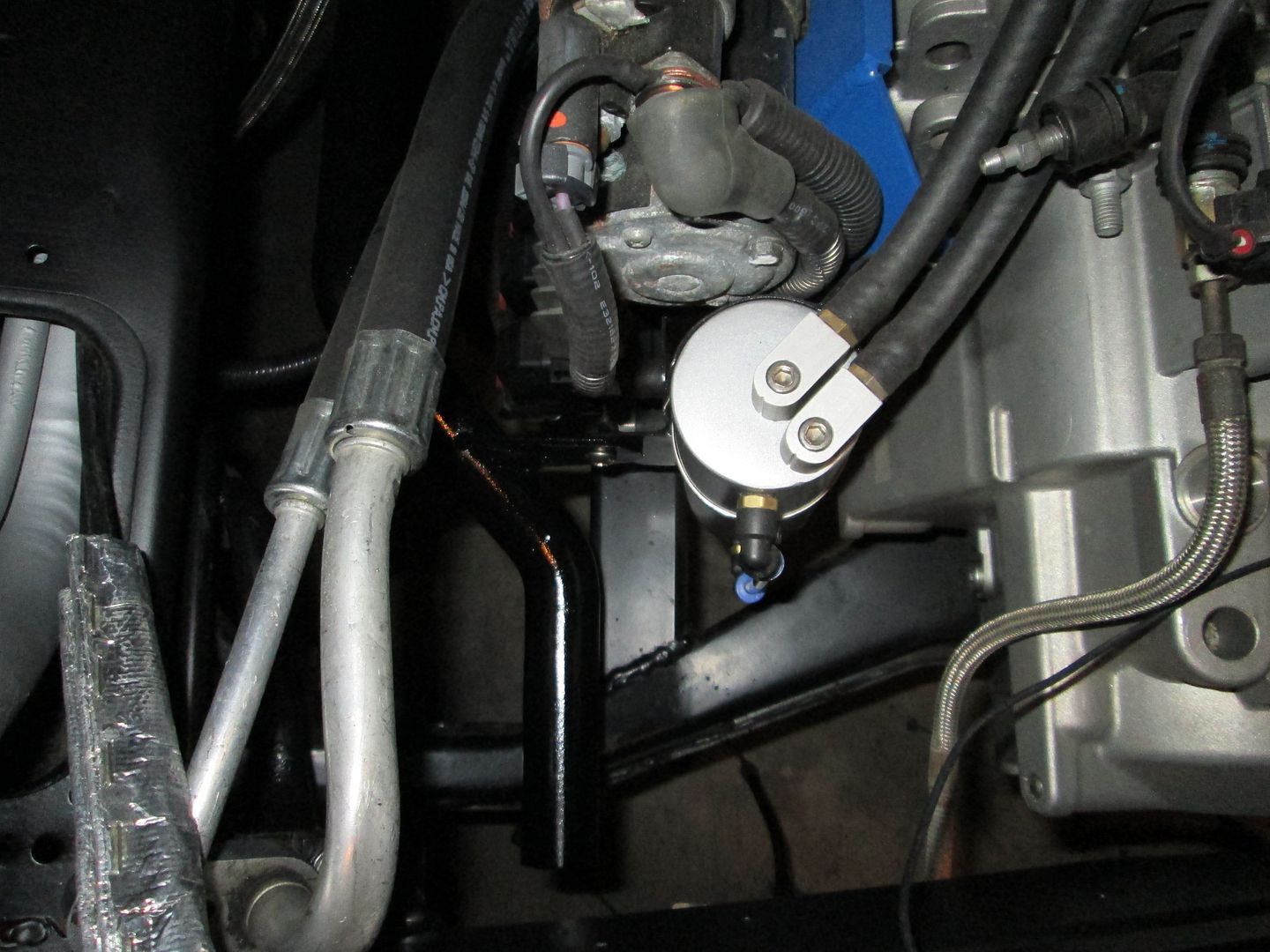
My engine developed a pretty bad leak here: the gasket actually ruptured out from between the head and the cam carrier, so there was constantly oil dripping onto the exhaust manifold and the catalytic converter, the engine bay smoked constantly, and it stunk pretty bad. This was the main reason the engine had to be pulled out in the first place.
This is how I get my engine in and out:
And one more shot of the interference on the F40 transmission with the cradle before I cut it out.
This morning while I was waiting for pipes, I decided to finalize the shifter cable bracket/turbo support. As I had left it, it was a few bits of steel just tack welded together, sharp edges, overhang... all that good prototyping nonsence! Looked something like this:
Removed
First step, Weld it up
Then, Round off edges, cut off excess metal, and sand blast
Then I decided to add a couple of extra reinforcements
Weld those in nicely
Some more sand blasting, then install.
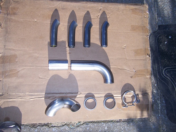
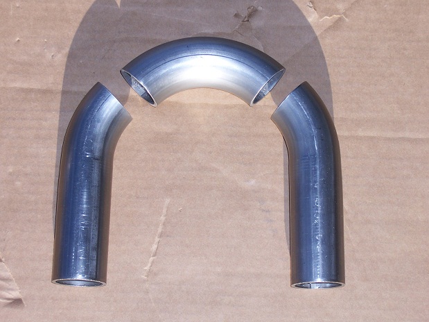
Once that was done, My piping that I need for the crossover/turbo manifold showed up! The large 90's are 2.25" 304 stainless weld joints, about 1/8" thick! All the other parts are for the wastegate, 1.5" bend, 1.5" flex, 1.75" 90, 1.75" straight.
Preliminary layout for the wastegate
The Proposed arangement somewhat in place
With the concept for the wastegate settled, I figured it would be time to look at what I have planned for the turbo drain. This was nice and simple, All I'm using is a 1/2" AN flare fitting on the bottom of the turbo, and a piece of 24" long 1/2" appliance gas hose. I decided this would be best because, as it is stainless, it can tolerate extreme temperatures, (that it should never encounter!) It acts as a coalescent for misting oil, and since it is thin, and has a bunch of surface area, the oil inside it will self cool. Hopefully it'll do as I think it will. It wasn't difficult to find that ideal mostly downward position for it. Don't know If I'm the first to do this, but I think its a great idea!
I just got started on building the Crossover manifold. There is going to need to be a collector just before the turbo, where I merge both 2.25" pipes into the single 2.25" inlet of the turbo. So what I'm going to do, is to run both exhaust pipes straight to the turbo one at a time, and mark their orientation on the turbo inlet flange, then I will draw a 50/50 center line across the two orientation marks, and cut the two individual pipes on that axis. If I get it right, then they will form a perfect collector. I will also have to cut a hole in the top of the collector for the 1.75" wastegate pipe that will point straight up. I'll post pics of this process.
So far, I did some trimming the two bends that I will be using for the front exhaust bank, and got a perfect fit for them. Hopefully tomorrow I will get some welding action on these pipes. There is not going to be any flex joint on this connection, just due to space reasons. The turbo bracket itself is flexible enough to accomodate the heat expansion that will certainly occur, and there will be a flex joint on the rear bank, down pipe, and wastegate. That should be sufficient.
Thats all I got for you folks tonight, Thanks for watching!
I made my shift cable bracket at the tranny adjustable and recall some remarks in descent about doing so, I believe flexibility even where it is not foreseen is important, GM included some adjustability with the originals. Many of the F40 transmissions are very difficult to impossible to shift into the lower gears in cold weather below 60 deg and often times I've had to start the car with the tranny in gear otherwise I would have to shut the engine off to do so until the tranny gets warmed up from use.
The potential problem with that is some times impatience sets in and you can start to force the gears stressing the shift cables. Light duty cables (Advance, Autozone, etc) will not hold up and even the good ones can start to show some fatigue as mine have a little, or the bracket may have bent a little. It still shifts fine when warm but cold initial shifts sometimes fall short of being fully engaged now which I can adjust for. You may want to consider at least a custom gear shift cable thicker than what's currently available for more firmness in shifts. I know Rodney makes a good cable, I purchased mine from the Fiero store and although not the same to my knowledge, they look exactly like the ones he makes regarding quality and are much better than what the local parts stores provide. It doesn't look like you'll have much room to work in that area once it's in the car so keep that in mind.
Disregard, I see now you have a cable source should it become a problem.
[This message has been edited by Joseph Upson (edited 02-13-2013).]
1/2" drain back from the turbo is cutting it very close, especially since it is angled which will reduce the flow rate from the turbo, you should have at least 5/8" to be on the safe side as oil comes through really quick after it heats up. If it's a ball bearing unit okay, but the coolant jacket tells me it's not. I'm speaking from having backed oil up into the turbine housing on a number of occasions. You don't want to restrict oil flow into the turbo unless you have to due to high pressure, not restrictive drain back.
The potential problem with that is some times impatience sets in and you can start to force the gears stressing the shift cables.
You're using two of what were originally designed as select cables, right? The cables designed to be shift cables are significantly more robust than the select cables.
quote
Originally posted by Joseph Upson: If it's a ball bearing unit okay, but the coolant jacket tells me it's not.
It is a ball bearing turbo. I thought that the BB center sections needed cooling jackets more than the journal bearing centers.
Originally posted by Fierobsessed: Once that was done, My piping that I need for the crossover/turbo manifold showed up! The large 90's are 2.25" 304 stainless weld joints, about 1/8" thick! All the other parts are for the wastegate, 1.5" bend, 1.5" flex, 1.75" 90, 1.75" straight.
Weld El's rock. It's good that you're going that thick for the hot side piping. I went with 11 ga mandrel bends for the primaries on my Northstar manifold... and it's not even turbo. A friend had a custom manifold made for his turbo MR2 Spyder a few years back using SS Weld El's.
Originally posted by Will: It is a ball bearing turbo. I thought that the BB center sections needed cooling jackets more than the journal bearing centers.
I'll have to check into the cables again as the thicker OE cables I had could not be used due to the larger cup size.
I remember reading differently about the ball bearing turbos due to reduced friction which also permits much less oil flow. I've seen them with both though and didn't see where he mentioned it was BB.
The oil inlet on this turbo has an oriface restrictor that is only .035" in diameter, the oil flow required is very low on this turbo. The drain hole on the bottom of the turbo is actually pretty tiny too, I think the 1/2" drain line isn't going to give me any grief. If it does, I'll source out some 5/8" line.
The one thing that sucks about the crossover manifold, is that although I have the 11ga weld el's, I still have to run the thin material at the manifolds, as they flare out on the manifold. It will be the most likely to crack where the two thicknesses are welded together. I wanted to use the weld el's due to there fairly tight radii that they have. Those buggers eat sawzall blades though!
I did some welding on the front bank crossover tube, I first started by putting the pipes in place and making a couple of alignment marks with a sharpie, then I remove the pipes and clamped the two together on my work table do a couple of light tack welds, and then do the full weld once I removed all the clamps. Here it is just before I tack welded it.
Traditionally, when you are tig welding stainless pipes together, you have to do what is known as a back purge. Essentially, you fill and run some of your shielding gas (argon) into the inside of the pipe, so that the oxygen in the atmosphere doesn't react with the metal on the inside of the pipe opposite the weld zone. This wastes a whole lot of shielding gas.
A friend of mine turned me on to this product called Solar Flux "type B".
This stuff is basically a super fine powder, that when mixed with methyl alcohol (I use HEET, from autozone) forms a paste. I apply the paste to the inside of the two pieces I'm about to tig together, then weld away. The heat of the weld causes the Solar Flux to turn into a hard glass like shell that insulates the back of the weld joint from oxygen, saving me a bunch of argon. Pretty neat product!
However, I've also read that it should not be used in a turbo manifold as the glass like substance it leaves behind could flake off and damage the turbo's turbine blades. But, I use the sand blaster on the inside of the joints, removing any and all traces of the solar flux. So this process leaves pretty clean welds, and no residue.
I am, by no means an expert welder. I am far too under practiced to be considered anything other then amature. But still, I enjoy the challenges of fabrication. So take any welding advice I give with a grain of aluminum oxide.
After that weld was done, I put the pipe inplace and had to do a couple of in situ tack welds to join the new pipe to the flange piece mounted to the manifold. Here I am about to do just that.
After the tack weld, final weld and some more sand blasting
I had a little extra time this morning and managed to get started on the rear bank tube. I welded the two joints as needed, and started fitting them into place.
The next challenge, now that I have the two pipes that need to join together at the turbo flange, I need to figure out exactly where to cut them to form a nice clean collector. This is actually pretty tough to do. I'm going to get my hands on some form of laser to draw out the lines on the pipes. I drew out the 2 orientation marks on each of the two pipes, then transferred the 4 marks to the turbo flange. Then I drew my 50/50 mark to indicate the spot where the seam will intersect the flange. This was a good starting place for marking out the collector Y. I'll get that going tomorrow hopefully.
Things are moving right along, and with that, the end of page 1.