Looks absolutely phenominal! I consider my DOHC swap pretty clean but your's is another caliber. I'm curious to see how it performs with the stock intake, other DOHC's I've seen have had short-runner intakes. No doubt the numbers will be impressive. Had Pontiac made the 1990 prototype an optional factory turbo on the DOHC would've been unreal!
I used a chop saw to make the merge for my waste gate, if your mid pipes meet on a level plane, it wouldn't be too hard, just cut at the center of the pipe, and weld. if I had done it, I would have started at the turbo and worked back to the manifolds though.
------------------ we're in desperate need of a little more religion to nurse your god-like point of view...
Mine aren't on a level plane, they are rotated about 5/8". Also, since I had to cut a little on an angle for the front bank pipe, they are also slightly lopsided, thus the need for a laser drawn line. In using a cutoff wheel for the rough cuts instead of the sawzall this time because I can be very careful with that tool. The sawzall tends to wander off on the other side too much for this critical joint. The line is slightly tilted and rotated from an even plane. I'll finish the cutting and welding of that joint tomorrow I hope.
To do the "Y" on the crossover, I needed to draw a somewhat accurate bisection line on my two pipes that I fitted to mate to the turbo flange. So I devised a laser setup, mainly my camera tripod, and a cheap laser line unit from Home Depot. These pipes were somewhat expensive, so I wasn't taking any chances of needing a re-do.
See the lines
Then it's back to the garage for some air cutoff tool action! It took a good 10+ Minutes to actually do this cut, but I kept it shy of the line so I could surface it to specification on the belt sander.
Tack welded one of the two pipes to the flange
Then, test fit the other pipe, a little work with the belt sander, then it fit perfectly!
Full steam ahead for the welds. Caution, Hot!
Picture showing what the inside looks like after a weld using solar flux to protect the back side of the weld.
Then, a couple minutes in the blast cabinet, not a trace left! But, you can see that the welds are a little lacking in penetration. In hindsight, It might not have been a bad idea to "V" the joint before welding. Oh well. Too late to do something about that. I got used to working with thinner metal... Still, got enough penetration to keep me from losing any sleep.
Another fit check, everything is spot on!
Next challenge, the Wastegate!
Ok, so heres what I have planned, a simple pipe welded to the Crossover's "Y" coming straight up, then a 90 towards the firewall, then the wastegate. Nice and simple!
So first I took the 1.75" piece of straight pipe, shortened it, cut it on an angle and ground the heck out of it till it fit tightly where I needed it to go.
Then weld, easy stuff.
Another shot of the inside, with the wastegate pipe in place. Tomorrow, I'm going to drill the wastegate hole, and maybe weld in the wastegate flange, and the 90. I don't have much time to play tomorrow. Till then...
Looks show room perfect, very impressive. Stainless expands more than mild steel so there will definitely be some stress in the merge pipe to the turbo without an expansion joint. Given the way it connects to the manifolds I believe you'll be able to resolve it by getting the pipes good and hot, then backing the bolts off just enough to relieve the expansion stress and tighten them back down before it cools that way when it does there will be a net compression force pulling the manifold ends together.
It will expand and bend. Just a matter of where. Mine bent the metal holding the turbo when hot which caused leaks between the logs and crossover when it cooled back down.
Expansion will not be an issue. I only have just this one pipe ridgid mounted. The turbo is bolted to a somewhat flexible mount.This pipe will push, pull or twist the turbo in any fashion it sees fit. The down pipe will have a flex, the wastegate has a flex, and there is a flex going in between the rear bank and what I have made so far. I am allowed 1 solid tube, just so long as every other connection or mount has some flex.
I got my morning off to an early start,
Wastegate feed before drilling
Wastegate hole from the turbo inlet flange, after some fancy work with a hole saw,
Then I pretty quickly got back into the welding, First I joined the wastegate flange to the elbow, then welded the elbow to the wastegate pipe from the crossover.
I welded the wastegate outlet flange directly to the flex pipe, and I'm holding the loose elbow wich I will probably have to get to tomorrow some time.
The fitment of the wastegate feed
And the crossover as it is now
Thats all I'll be able to do today. Tomorrow, I hope I will be able to do the little elbow for the wastegate outlet to the down pipe, maybe even get the rear bank tube, flex, and flare all in place. That would complete the crossover and wastegate system completely.
Did a bunch of work today. First, my intention was to finish the wastegate plumming. I cut the hole in the downpipe, formed the elbow to fit it, and welded the elbow to the pipe, then to the flex tube.
All bolted up
With the wastegate system all buttoned up, I turned my focus to the rear bank exhaust pipe, this is what I came up with. This is the flex that allows expansion of the crossover tube without cracking.
All welded up. This concludes the building of the crossover, which is probably the most difficult part about creating a turbo setup.
I put the engine back together, a bit to make sure everything is going to fit and work. I do have to grind just a little bit of material off of the lower intake manifold, No matter what I did it was going to hit the crossover pipe, there just wasn't enough room back there, I figure 1/8" of clearance is good enough, and its not an important chunk of aluminum.
In the final install, I plan on wrapping the crossover tube with some "Lava Rock" header wrap. The crossover passes the charge pipe, the air filter and the turbo compressor housing. I need that pipe to give off minimal heat to the engine compartment. I might even make a metal shield to go around the wrap, or to shield the air filter and compressor housing I'll cross that bridge when I get a bit closer to finished.
I need to rip the engine off the cradle, notch the cradle for the transmission clearance, do a little reinforcing of the rear cradle. So that's next.
To do list: Make a mount for the intercooler Do some small piping for the wastegate and BOV controls Make new fuel lines that work around the turbo Make a new water neck that works around the turbo New 3" exhaust system Add plumming for the intercooler water lines and pump Wiring harness
There are a bunch more things to do... but honestly, I think the hardest part is now in the past.
[This message has been edited by Fierobsessed (edited 02-18-2013).]
In the final install, I plan on wrapping the crossover tube with some "Lava Rock" header wrap. The crossover passes the charge pipe, the air filter and the turbo compressor housing. I need that pipe to give off minimal heat to the engine compartment. I might even make a metal shield to go around the wrap, or to shield the air filter and compressor housing I'll cross that bridge when I get a bit closer to finished.
I'd recommend ceramic coating inside and a metal heat shield vice the header wrap... Wrap really keeps the heat in the metal
Originally posted by Will: I'd recommend ceramic coating inside and a metal heat shield vice the header wrap... Wrap really keeps the heat in the metal
I've thought a bit about ceramic coating. My fear is that if anything chips off, anything at all, it will damage the rediculously expensive turbine.
No matter what, I absolutely must keep the radiated heat to a minimum on the rear bank tube. The header wrap, with a metal shield is closest to what the factory used, except the temperatures may be quite a bit hotter in this setup, so I do have my concerns about it too.
quote
Originally posted by fieroguru: Great job on the fabrication and welding! Everything is displayed in a neat and orderly fashion.
Thanks! I think we share the same love for fabrication! Might even over do it just a bit
Not sure if there is room, but you may try to fit an intake tube to the turbo so the filter/air intake can be further away from any heat. The added benefit is you could do more to keep the intake tube cool (coated, wrapped, etc) without worrying about long term impact due the low temp that the tube would see. Then you could do less on the exhaust side.
Another option would be to add a few heat shields tacked to the exhaust. Something like these:
Just got back from a little vacation, a few parts are on order and on the way. I'm waiting on a catalytic converter with 3" metal substrate, some more 3" pipe, an oil feed line, some fittings, a turbo blanket, 1.25" bend pipes and a piece of metal to make a flange for a new water outlet. Hope I don't run out of argon! I've still got a LOT of welding to do!
My next focus is on cleaning the cradle, clearancing it for the transmission, Then I will do the water outlet and the remainder of the exhaust.
Getting 3" to pass between the front engine mount pad on the cradle and the oil pan is really tight. It does fit, but only just. there will be a little bit of the exhaust below the bottom of the cradle, I've resigned to this fact, but it's no big deal.
Weld the bugger in (will clean up this rather crappy weld later)
Fit check shows that the notching was a bit excessive, but extra room is better then not enough!
Once that was done, the parts to build the new water neck showed up. I purchased 2, 304 stainless16 gauge 1.25" mandrel bent 180's one with a tight 1.8" radius, the other with a loose 3.6" radius, and I got a 4X6" piece of 1/4" 304 Stainless plate.
My original intention was to have the water outlet come out and make a sharp 90 up and the long radius to go around the turbo's air inlet. This is what the outlet looked like with the turbo and air filter in place.
After some careful reconsideration of that plan I found I could squeeze the pipe in going downward and run it under the turbo towards the coolant piping on the car. Much shorter, much neater. So I made a couple of cuts, and one weld, and this was what I came up with:
And in place,
Once I had a better idea of how the pipe needed to be run, I cut another piece of pipe, this time with the long radius and welded it to the first pipe.
Next was straight on to the flange.
A little fancy work with the sawzall and the belt sander
Drill some holes
Mount it up with the thermostat in place for the fitment of the pipe
I then put the pipe in place, first with a couple of tack welds, then I removed the flange and pipe and finished the weld.
Looks pretty good!
With the Air filter in place,
This is where it is exiting seen under the turbo, in front of the transmission
That is it for the water neck for the time being. I will have to come back to it to add a bleeder (filler too?) and one support, possibly add another pipe to it to bring it closer to the under car coolant tubes.
I also recieved a couple of other goodies. I got my oil line, 36" -4AN stainless braded line, with a 90 on one end, and a straight on the other, and my turbo blanket. It'll go in something like this:
I also recieved a 3" metal substrate catalytic converter. Honestly I'm a bit dissapointed with it. It's just so dinky I don't know how well it will flow. Its 3" inlet and 3" outlet, yet its only 4" in diameter! But being that it has a super fine metal substrate, I guess it keeps the bulkiness down to a minimum? I've decided that I will V-band the inlet and outlet into place. So If I hate it, I can change it out, or hollow it out for the dyno and put a larger cat in for the street... or whatever I want to do!
I chose to run the dump into the exhaust for three reasons. I don't like to breathe exhaust fumes, a dumping wastegate could be viewed as an exhaust bypass by a keen eyed emissions inspector. And I kinda want this car to be moderately quiet, and not totally obnoxious on power either. Really there was no great reason to do an atmospheric dump, other then a lower back pressure when the wastegate is open.
As for the old exhaust, the jury is still out on it, I had planned on re using the muffler and tail pipes, but I'm starting to waiver on the idea of doing that, it is a complete almost all stainless 3.4 dohc exhaust system... Including the crossover...
I love the sound of my dump. How does it help with boost control asking cause i'm curious.
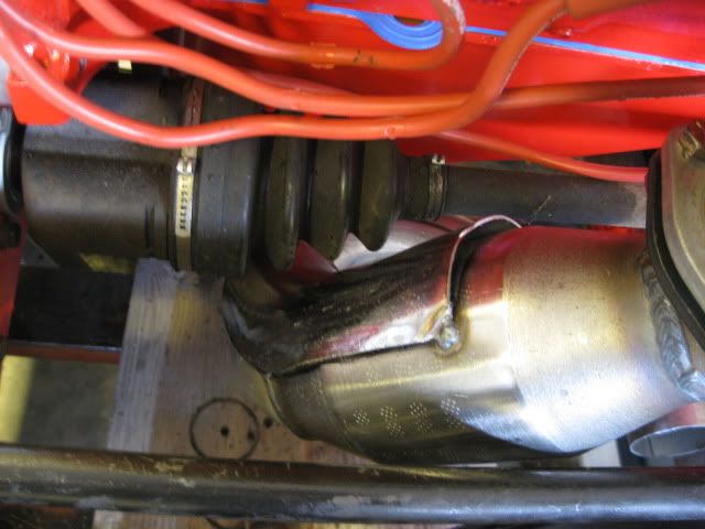
Open dump is best for all out performance since redirecting exhaust back into the mainstream disrupts flow as well as potentially affects boost, good and bad depending on what you're trying to accomplish, but ultimately the noise level would be the determinant for me. I've run both and currently run open dump just behind the inboard cv joint and because of the length and size of the dump pipe, it makes the sound heard when blowing over the opening of a jug when it opens.
The location of his wastegate would very likely allow fumes to roll back into the car if it were open dump, unless the dump pipe was unusually long and exiting near the back of the car. One thing for sure, if you don't have enough exhaust flow it will not matter much.
Originally posted by darkhorizon: Physics of the main exhaust flow leaving the turbo and a proper angle of the dump tube will effectively suck exhaust out of the wastegate.
I don't know dark, I don't have access to Maximum boost at the moment for all the specifics but I'd expect the velocity of the dump exhaust to be higher than the main exhaust leaving the turbo and likely to serve as the source of instead of being subject to any scavenging. The transition into the main will have an effect for sure depending on its arrangment.
Physics of the main exhaust flow leaving the turbo and a proper angle of the dump tube will effectively suck exhaust out of the wastegate.
Still really don't see what that has to do with the Waste gate opening and closing in turn controlling boost... Either way i'd rather have as little back pressure as possible and being a younger guy my loud exhaust system doesn't bother me.
Still really don't see what that has to do with the Waste gate opening and closing in turn controlling boost...
It doesn't. I'm sure he means that with the lack of back pressure in the exhaust for the dump gives it more capacity to flow out the necessary gasses to keep the turbo's speed under control. This is true when you are running your wastegate on the ragged edge and you need that extra flow of an external dump.
But to that, the arguement can be made that if your exhaust adds enough back pressure to your wastegate to cause boost creep, it also adds it to the pressure at the outlet of the turbo, and that decreases boost. But if you're running into those kind of issues, your exhaust system is FAR too restrictive to begin with. That's why I'm contemplating a different muffler at the moment. I did some asking around and word on the street is that although my old Flowmaybe 80 series crossflow sounds great, it does NOT flow, and that I need to look into straight through, bullet style mufflers.
My goals aren't too lofty. Over 400, under 500. The turbo can do 600. But honestly, the engine is pretty much stock, so I think doubling the 210 from the factory, and then some is reasonable. I only plan on studding the heads down, possibly the bottom end too.
On another topic of interest at the moment. Clutch selection! I've done quite a bit of research lately. But no matter where I turn, the waters get muddy. It seems that the clutch I want might not exist, or is so rediculously expensive that I would never consider using it.
The good news is that the F40 transmission has a common spline count and diameter, and a very common disk diameter too. Cars that have a 1" 23 spline shaft, and around a 240mm disc... a bunch of Fords, pickups, explorers, probes and focuses Most Mazda's even including RX cars a buttload of Porsche's if not all of them. Mitsubishi's, especially the lancer evo cars
So there is no shortage of potential disc sources, and plenty of high power applications.
I really want a low inertia disc. I absolutely LOVED my clutchnet Kevlar sprung disc that was in the car with the Getrag, but it was WAY to heavy. I could tell that the synchros were struggling with every shift, and with the high RPM 3.4 DOHC, it was taking its toll. After 30,000 miles with the 3.4 DOHC, this is what came out, note the minimal dust.
unbelieveably, this is what the pressure plate surface looked like!
You can see that the original machining is fully intact. The flywheel looked the same, and there was virtually no wear of the clutch material itself. It also held quite well, only once it broke in.
very little dust in the bellhousing and on the pressure plate too!
So for the most part I was VERY pleased with this clutch disc, and I plan on installing it on my 3800/F23 with a stiffer pressure plate. But that's a story for another thread.
I really took an interest in the Porsche disc's They so clearly have minimal inertia.
However, I don't like the idea of using an undampened clutch disc. They can beat a transmission, or drive line to death. Every engine crankshaft pulse needs to be absorbed at the clutch, using a dual mass flywheel works, or a dampened disc. I plan on making a custom flywheel, using a SPEC high clamp pressure plate. But what disc??? Anyone have any ideas?
I have the clutchnet 6 puc disc and found that it performs very well, with minimum chatter. its the sprung hub though. thats about as aggressive as Id want to go to keep it streetable.
There is an aftermarket flywheel available in aluminum that supports the stock G6 clutch and pressure plate. I had the stock pressure plate checked and it produces 2000 lbs of clamping force so I highly doubt you need to place any focus on that given it is as high or higher in clamping force than most of your aftermarket performance pressure plates for the typical run of lesser trannies for the 60 degree motor. You should look into a disc better than stock though.
I use a Kevlar disc based on the stock G6 hub which I don't recommend now because of minimal damping ability. The picture below is of my options at the time I had it made and I went with the circular arrangement seen below over the puck. My flywheel is a modified unit from the F-body with a stock already HD pressure plate relative to the OE Fiero plate at the time it was produced, that was modified to produce about 2300 lbs of clamping force. Stock was somewhere around 1600 lbs of clamp force I believe.
[This message has been edited by Joseph Upson (edited 03-04-2013).]
I have a 2.8/3.4 camaro flywheel. So I have a pretty good idea what I am going to do with that... I have a lathe too, and I am not afraid to use it!
Maybe I will have a custom clutch made. Ideally I would like to get the disc's weight down a bit. I hate heavy discs. Maybe that 4 puck is the trick I need
Edit: 240mm diameter, 23 spline X1", very light weight... $119. Could be as good as it gets? Might be a bit harsh though.
[This message has been edited by Fierobsessed (edited 03-04-2013).]
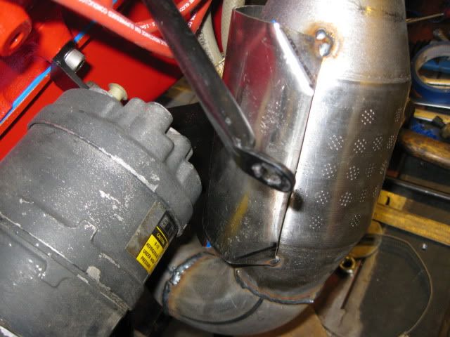
It's been mentined, and I don't know if you adressed it or not, but having your air filter so close to the manifold will probably destroy it. It gets HOT in there. Glowing hot.
The wastegate may survive so close to the hot side of the turbo, but it may also self destruct, or worse, start sticking. sticking closed would be bad. If you have room, I'd extend it away from the turbo, or use a turbo blanket/shield of some kind.
I can only wish my welds were that good!!!
EDIT:
I see that you are using a turbo blanket. Very good. I'm still concerned for your air filter though.
For my knowledge (I have a 3.4 DOHC sitting in a box in my basement), where do the F23 control cables hook in? For the Muncie 4speed, those cables are why I couldn't locate my turbo there..too much heat for the cables. Forgive me if this is a dumb question..I know nothing about the F23).
Chay
[This message has been edited by Slowbuild (edited 03-04-2013).]
Originally posted by Slowbuild: The wastegate may survive so close to the hot side of the turbo, but it may also self destruct, or worse, start sticking. sticking closed would be bad. If you have room, I'd extend it away from the turbo, or use a turbo blanket/shield of some kind.
I can only wish my welds were that good!!! Chay
That's the kind of thing you worry about with Ebay special wastegates, name brand shouldn't be a problem not to mention that a street driven vehicle is not likely to encounter the kind of extremes that cause that kind of threat to the wastegate. The one example I saw of an aftermarket wastegate sticking was in an unscientific, impractical unrealistic setting where it was heated to glowing hot temps and opened and closed continuously until it stuck which took several minutes and far longer than any street driven vehicle would come near matching.
It's been mentined, and I don't know if you adressed it or not, but having your air filter so close to the manifold will probably destroy it. It gets HOT in there. Glowing hot.
The wastegate may survive so close to the hot side of the turbo, but it may also self destruct, or worse, start sticking. sticking closed would be bad. If you have room, I'd extend it away from the turbo, or use a turbo blanket/shield of some kind.
I can only wish my welds were that good!!!
EDIT:
I see that you are using a turbo blanket. Very good. I'm still concerned for your air filter though.
For my knowledge (I have a 3.4 DOHC sitting in a box in my basement), where do the F23 control cables hook in? For the Muncie 4speed, those cables are why I couldn't locate my turbo there..too much heat for the cables. Forgive me if this is a dumb question..I know nothing about the F23).
Chay
The pipe will be covered and insulated. The crossover is not as close as it appears in one of the pics above. I will address all of that heat shielding and insulating towards the end of the build.
Thanks for the compliment on the welds, I am getting better at it all the time. A the end of the day it is A LOT of stainless welds!
What Joseph Upson said is absoutely true. A nameless or cheap knockoff wastegate might be questionable. But this is a TIAL, it is their latest and greatest model. the MV-S which they run all day long glowing red hot without issue in tests. It is even water cooled, which they said is not necessary for my application, but I'm going to hook it up anyway.
Anyway... Today's progress report.
I started this morning with a run to the Pic-a-part, looking for a factory oil cooler, and much to my surprise I found a 91-93 LQ1, with the oil cooler! I yanked all related items to convert my engine over.
Cleaned the parts up a bit. The water feed actually comes from a brass fitting screwed into the coolant drain plug in the block. The water neck has a few spots where the aluminum was completely rotted through. But I have to use this water neck it has the return from the oil cooler. The 94-97 engines don't have the port, maybe I can fix it with epoxy, or TIG it.
Next I began tackling the 3" part of the exhaust. I started with this 180, I cut it at 45 degrees to form the question mark shaped pipe that the Fiero's stock exhaust system has.
Tried a fit up, found I needed to add a 1.75" long straight to the sections to make it fit nicely.
Welded up
Then, I welded the V-band flanges to the catalytic converter, and started doing some more fitup.
At this point, I'm calling it a night, perhaps tomorrow morning I'll get the remainder of the exhaust from the downpipe to the cat finished. We'll see how that goes...
Originally posted by Fierobsessed: However, I don't like the idea of using an undampened clutch disc. They can beat a transmission, or drive line to death. Every engine crankshaft pulse needs to be absorbed at the clutch, using a dual mass flywheel works, or a dampened disc. I plan on making a custom flywheel, using a SPEC high clamp pressure plate. But what disc??? Anyone have any ideas?
Sprung hub clutch disks and dual mass flywheels ONLY reduce gear rattle in the transmission. They are for noise reduction ONLY. End of discussion. (Except in the case that the secondary mass of a dual mass flywheel actually slips from the torque, but that's not a normal mode of function).
Think about it... How stiff would those springs have to be to prevent engine torque from simply compressing them into coil bind and making a solid connection? When my Northstar destroyed its first Centerforce and I sent the disk back, the tech who looked at it noted that the travel stops in the hub were beaten flat... So obviously the springs in that hub had nothing to do with cushioning engine torque.
I have to disagree for two reasons Will, first the dualmass flywheel for the F40 does not use springs, or springs only, as I tampered with one of the OE flywheels short of disassembling it and some type of grease came out of it. Second, within the design parameters of the stock dualmass application the flywheel may offer shock protection in the same manner that smooth clutch engagement as opposed to a clutch pedal slipping dump does. It definitely quiets the tranny down but I do not believe that is its sole purpose as it should be capable of damping the firing pulses in the same manner that the harmonic balancer does as long as it is not static which should be the case under most if not all conditions in the stock application. It is designed to slip also at its torque limit. Whatever the case, the over all mass of the flywheel may be the real protector as opposed to the limited independent movement of both parts.
The torque needed to compress the springs till it hits the stops on the OEM F40 disc is roughly 1-2 lb/ft. Those springs don't do squat! I can only guess that their purpose is to allow the some give to shift if the meshing is close enough. For all intensive purposes, the F40 disc is a solid disk. Any torque at all hits the stops. The function of the springs is moved to the flywheel on a dual-mass which technically speaking, is a better place for it. Less inertia in the disc, longer synchro life, better shifting.
On my clutchnet disc, Its probably in the 100 lb-ft range to compress them fully. Let's just say it was extremely tough to check them out. The springs are VERY beefy. Im sure in any event that when you are accelerating heavily, no matter the clutch, that you are driving the wheels undampened, but with the higher RPM of hard acceleration, the weight of the flywheel smoothes the pulses out beautifully anyway. It's not like you spend a lot of time in this condition.
I agree Will that the springs, or the dual mass flywheel reduce noise. But I'm saying that in addition to that, it directly reduces spline fatigue and fretting. (at the clutch disc, at the dog rings, at the axles... ect.) Joseph Upson lost his 6 speed from what is believed was most likely caused by the fatigue of having ZERO give in the driveline, with the engine at low RPM's in 6th gear for an extended period of time, which is a normal mode of operation for 6th gear. The evidence supports it.
Either way, I'm going with a light weight design sprung disc and a solid normal weight flywheel. But I am stil trying to find a disc with that magic combination that gets me light weight, Torque capacity, drivability and durability for a reasonable price. Thats a real challenge! I've seen some very interesting discs out there.
[This message has been edited by Fierobsessed (edited 03-05-2013).]
Originally posted by Joseph Upson: damping the firing pulses in the same manner that the harmonic balancer does...
If you're basing your understanding on that, you need to do some more research into how a harmonic balancer works.
The harmonic damper absorbs the torsional "ringing" in the crankshaft but does absolutely nothing to reduce peak output torque from the engine.
quote
Originally posted by Joseph Upson: Whatever the case, the over all mass of the flywheel may be the real protector as opposed to the limited independent movement of both parts.
I think it's pretty well established that increasing flywheel weight increases transient loading on shifts. The transient loading from decelerating the flywheel is far greater than the engine's actual output.
That's why first gen CTS-V's with stock flywheels tend to blow their diffs apart, while those with lightweight flywheels don't have that problem to the same extent.
quote
Originally posted by Fierobsessed:
The torque needed to compress the springs till it hits the stops on the OEM F40 disc is roughly 1-2 lb/ft. Those springs don't do squat! I can only guess that their purpose is to allow the some give to shift if the meshing is close enough.
It's noise reduction and only noise reduction, pure and simple. Thank you for making the measurement and posting the numbers.
quote
Originally posted by Fierobsessed: I agree Will that the springs, or the dual mass flywheel reduce noise. But I'm saying that in addition to that, it directly reduces spline fatigue and fretting. (at the clutch disc, at the dog rings, at the axles... ect.) Joseph Upson lost his 6 speed from what is believed was most likely caused by the fatigue of having ZERO give in the driveline, with the engine at low RPM's in 6th gear for an extended period of time, which is a normal mode of operation for 6th gear. The evidence supports it.
That doesn't pass my sniff test.
A car that *ACTUALLY* has a spline fretting problem is the BMW E30 325iX where the front driveshaft is driven by the transfer case. That ONLY happens when the incorrect lubricant is used in that spline interface. That driveline has THREE rubber flex disks in it AND a sprung hub clutch.