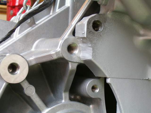
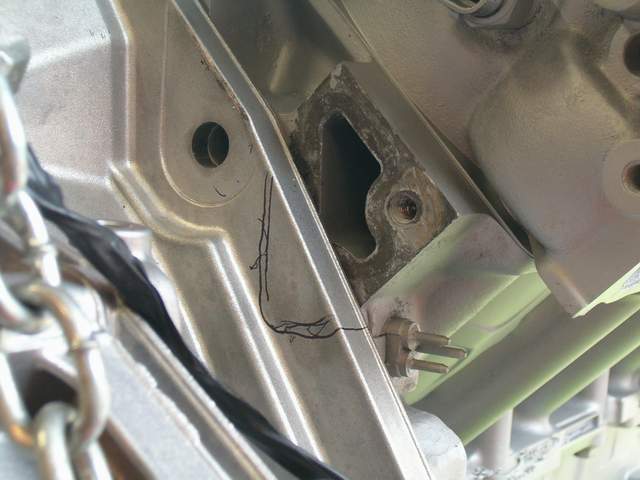
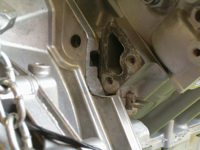
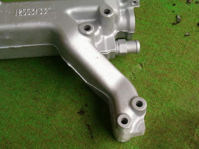
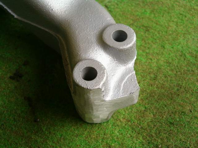
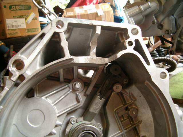
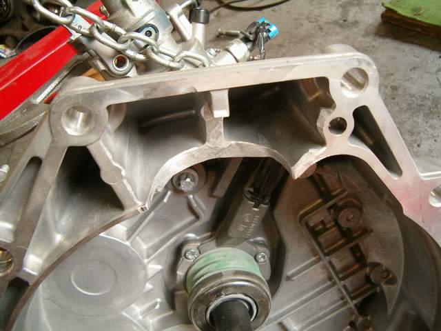
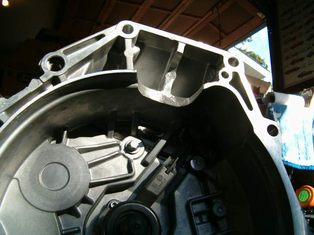
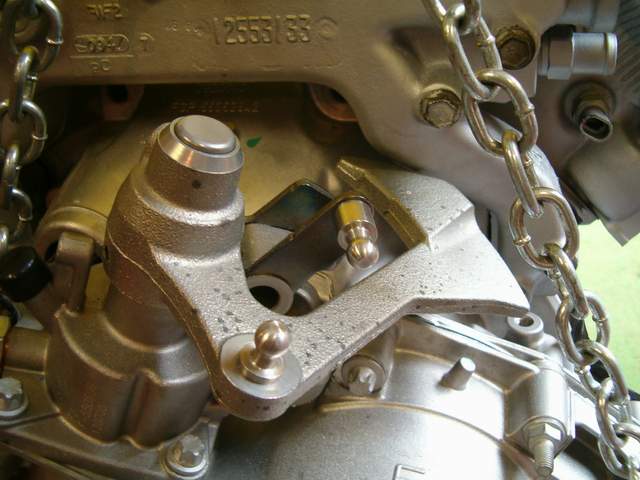
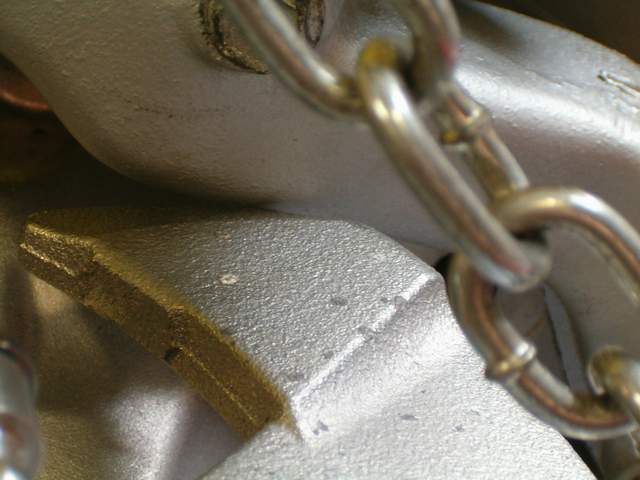
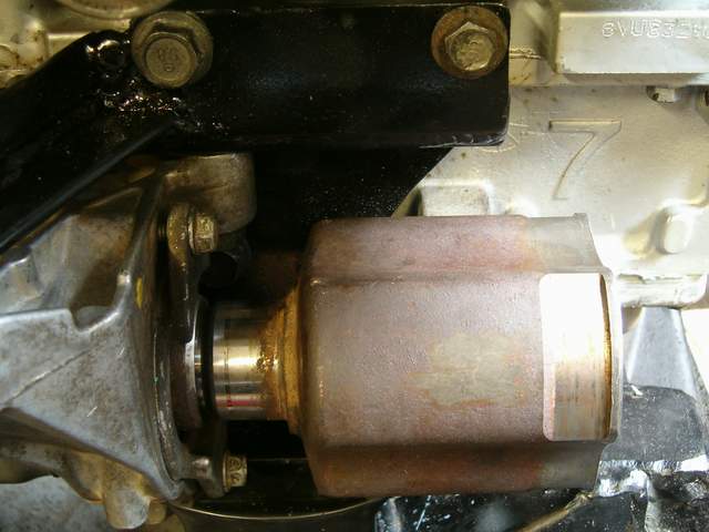
Well i didn't want to start this thread until i was finished but i guess i will just post the work as it gets done. The big question was can a northstar be mated to an G6 6 speed and it can. The first step i went through is getting the trans to bolt up to the engine. The right side of the northstar block must be notched and an adapter made to relocate the lower rear bell housing bolt. This also has to be done when using a getrag. The lower rear water passage of the water manifold interferes with the bell housing. So the bell housing must be clearanced and the area around the bolt hole on the water manifold can also be ground slightly. Just like the getrag the inside of the bell houseing must also be ground to make room for the top mounted starter. The shift mechanism clears the water manifold without a problem. The shift counterweight is the closest to the water manifold when the transmission is in reverse. I'm not sure if you can tell or not but there is about 1mm clearance between the weight and the manifold when in this position. Those are all the modifcations necessary to get the g6 trans to bolt up to a northstar. Hopefully tommorrow i'll be able to tackle the new mounts.
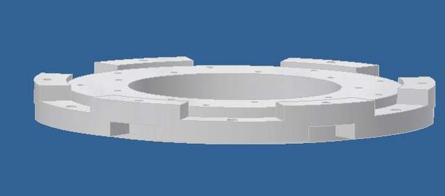
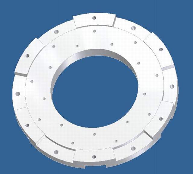
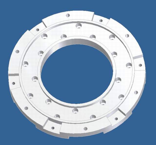
Yeah it was probably me but I think there were a few others that were interested in it. I'll be reusing my aluminum spec flywheel and am going to CNC an adapter. This is the design i'm thinking of using. The design isn't final but let my know what you think and what i can improve on it. With this design the adapter weight will be 5 lbs.
Sorta related question. I see you have a hydraulic release bearing, I guess all 6 speeds have this, but what do you do for a clutch master? Does the Fiero master work ok with the release bearing? Reason I am asking is because I am looking for a getrac, but most of the ones I am looking for used the hydraulic release bearing.
------------------ 84 Fiero Sport Coupe #1192 :: 86 Fiero Base Coupe Quad 4 HO :: 1998 Dodge Neon EX 2Dr 2.0L DOHC Auto
This is the one peice flywheel used for the 3800 application to the 6 speed (F40). This same flywheel can be made with the differance of the crank bolt holes and balancing.
First to answer a few questions: I'll be using the stock g6 final drive ratio I'm not going to cut off the counter weight because it doesn't interfere with anything
Team race tech how much would it cost for a one piece flywheel? I'm definatly interested but i should probably follow through with my own plans since i have already bought the $130 (ouch!) piece of aluminum to make my adapter from.
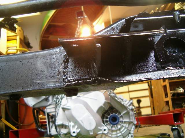
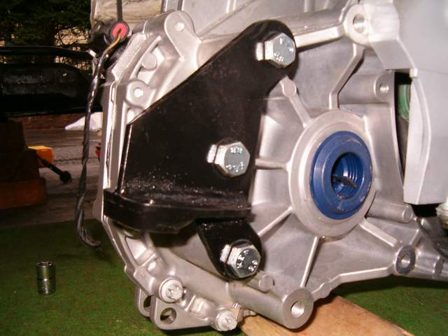
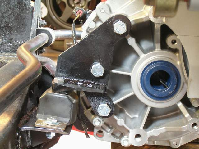
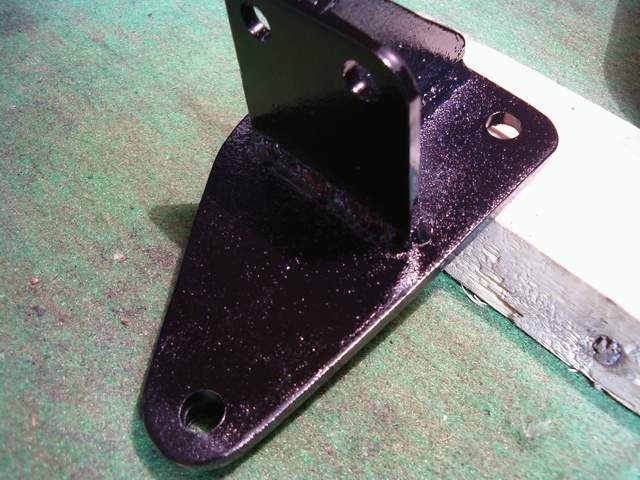
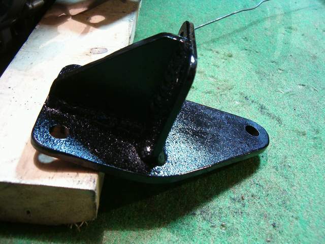
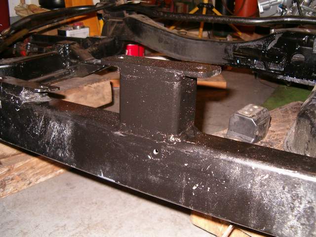
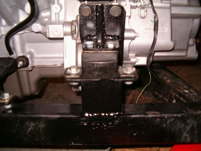
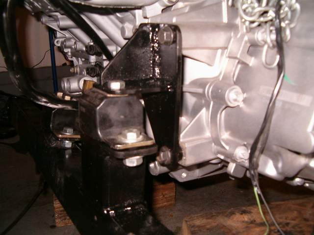
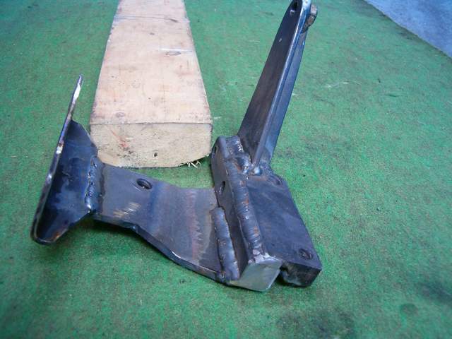
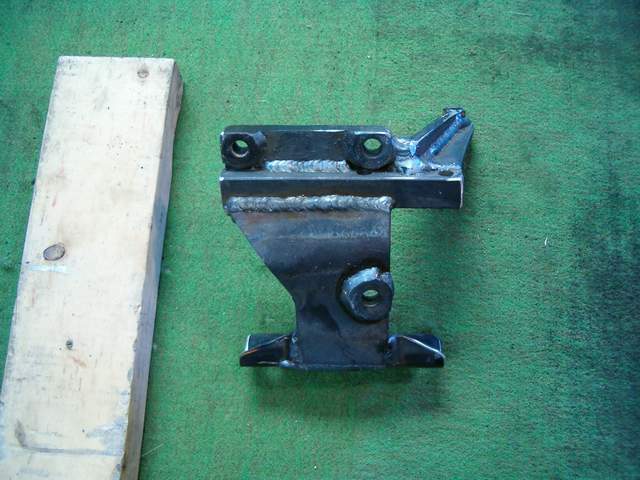
Today i got the mounts finished. All the mounts are made from 1/4" plate and the mounts themselves are energy suspension poly GM transmission mounts. I started with making the rear transmission mount. Then i made the frame mount part of it, added a few gussets and a large piece of scrap i had lying around to sort of box up where the old mount used to be. Then i started working on the front tranny mount. And the frame part of the mount. The last few pictures are crappy because it was getting dark. Next step will be to make the intermediate shaft bearing support.
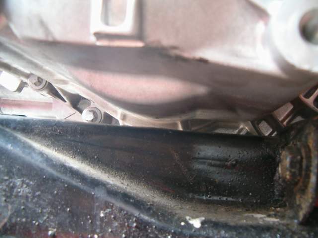
I solid mounted my setup when I couldn't find the poly interlocking trans mounts locally at the time I wanted them. I have an 86 so my cradle is different. I was trying to get a good look at your clearance but couldn't get an idea since there are no pictures of the two key areas I noted on mine. The bottom of the trans over the driver side of the cradle has about 1/4" clearance and about the same for the front edge near where the front tranny mount would go so it's about as low as reasonably possible as well as close to standard specs. If I had the time for such a project I would have liked to have modified the cradle to allow for at least a 1" lower position relative to stock. That's about as far as I could go before the oil pan protrudes below the cradle.
The flywheels are pricey, mainly they are made to order and no quantaty is made. For the one peice aluminum with steel friction surface and balanced to match the stock northstar flex plate, this will work with a standard custom clutch design like the one used for the 3800 application ( pressur plate and disk) with the exception the G6 input spline hub $750.00 CDN.
Joe
------------------ Street Legal Tuning.
Specializing in Fiero performance: 3800 swaps, custom Aluminum flywheels, Brakes, Engine's, Aftermarket Bolt on performance parts, used Fiero parts, www.iactech.com e-mail: joetrentadue@hotmail.com
I have about the same bottom clearance that you do, it's about 1/4"-5/16" between the bottom of the tranny and the top of the cradle rail. My oil pan sits about 1/4" higher that the bottom of the cradle.
Hi Joseph, A question? back in you first post when you started with the quest to building your swap you had said you went to a auto parts store to look at some similar clutches that use the same number of splines as the G6, if i'm correct was it from a ford Ranger? now that you have a custom clutch what center hub did they use? and will the one from ford work?
There are a few different ford ranger clutches that all have the right spline and diameter, all the 3.0L V6. 95-97 98-00 01-03 and 04-06. I had a look at the first three models and found the first two to be exactly what i was looking for, they both use the same disc, and from what i can tell the same pressure plate, just the TOB is different. The 01-03 center hub section with the springs was very thick, if using the fiero pressure plate the fingers would definatly contact the disc. If i end up buying a disc from spec it will be from the 99 Ranger 3.0L.
There are a few different ford ranger clutches that all have the right spline and diameter, all the 3.0L V6. 95-97 98-00 01-03 and 04-06. I had a look at the first three models and found the first two to be exactly what i was looking for, they both use the same disc, and from what i can tell the same pressure plate, just the TOB is different. The 01-03 center hub section with the springs was very thick, if using the fiero pressure plate the fingers would definatly contact the disc. If i end up buying a disc from spec it will be from the 99 Ranger 3.0L.
when I did my Northstar/Isuzu swap I got the clutch, pp and flywheel from CHRF. they use Mccloud products and have a very nice clutch setup they use for the sand rails etc. just tell Alan what spline you need and he should be able to fix you up. I'm running a stock vin9 motor and have seen zero slippage and engagement is very smooth.
Sorta related question. I see you have a hydraulic release bearing, I guess all 6 speeds have this, but what do you do for a clutch master? Does the Fiero master work ok with the release bearing? Reason I am asking is because I am looking for a getrac, but most of the ones I am looking for used the hydraulic release bearing.
It does work ok. You just need to mate the slave line to the HB.
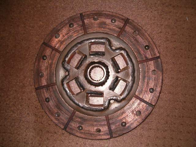
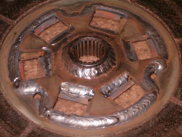
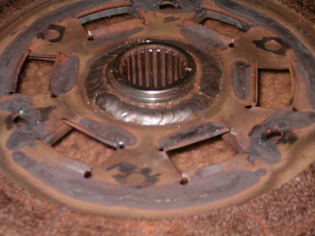
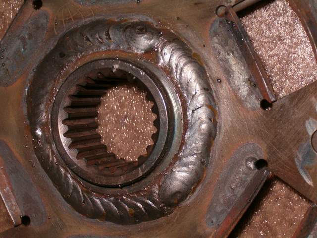
Well i made my clutch disc today. I have a spec stage 3+ clutch that i only put a few hundred km's on with the getrag and i really wanted to re-use it. From what i've read some of the higher powered manual guys are having problems with sprung hubs, and after switching to a solid hub clutch everything was fine. They say the engagment really isn't all that much different and i really dont mind a rough ride. I was thinking about buying a stage 4 disc from spec for a 99 ford ranger but that would cost 250-300 at least. So instead i decided to modify my stage 3+ into a stage 4 and convert it to the correct spline. I used the center hub section from an 88 ford ranger 4 cyl i think, all rangers have the correct spline, and welded it in the center of my stage 3+ disc. I figure the worst case scenario is that it either breaks or i dont like how it drives in which case at that point i will buy a proper disc. But for only $20 i'd like to try the welded disc just to see what it's like. The center section looked like it was two pieces, the spline looked like it was pressed into the flange, so the first step i did was weld that in solid. Then i put it in the lathe and turned one of the welds down so it was a nice fit inside the center of the clutch disc. Then tack welded in a few places and then welded it up. It only warped slightly (a hundredth maybe) although i don't know if it was even perfectly straight before, either way i'm not worried about it. The welds are relatively symetrical so i'm not to concerned about ballancing. Like i said it was only $20 to modify it and worst case scenario is i have to buy another disc, but i'm pretty sure it's going to work just fine. I've also been thinking about how i'm going to modify my axles. I'm starting with the intermediate shaft and axles from a supercharged cobalt ss. I think i'm going to weld the axles but i'm not sure which way. There is a circle track place locally that grinds the axles down to points and welds them up from there for $100 each or i was thinking of welding a beefy sleeve overtop of them. My old shop teacher has had great success with the sleave method. I'm also thinking about haveing them cryo treated after welding to increase their strength, but the idea is to keep the cost down, i guess we'll see when it comes time.
[This message has been edited by Zac88GT (edited 09-27-2007).]
Great information, I'm following very close. I'm working on a 4.0 Aurora with twin turbos and the six speed! So your tread is helping me along. Great built!
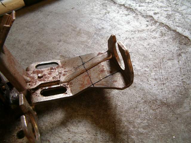
Last night I was able to modify the 4-speed shifter that i picked up last weekend and make the shift cable bracket for the transmission. Since i will be using two getrag 5-speed select cables, the shift cable mount on the shifter had to be moved closer to the shifter by 1.5". This was make sure the cable was in the middle of it's travel range when the shift lever was centered. In josephs 6-speed thread he just cut the tab off of the shift lever so it could no longer hit the stops, this would have been easier but i didn't want to do it because i thought it would change the position of the shifter in the car, and i was very comfortable with it's original location. This is the shift lever in the centered position.
Here you can see the line marked 1.5" forward of the face of the mount. The face of the cable bracket should by 5/8" from the bend just aft of the bolt holes for another reference. And the bracket hole should be centered on the outside edge of the square mounting plate.
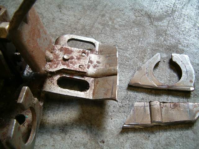
After cutting.
After welding.
Painted with gussets.
Next the limit slots on the shifter had to be elongated towards the drivers side to make room for a 5/6 gate. After a little measuring i figure the shifter requires about .5" travel per gate so 1.5" min total cable travel is required. Stock is about 1.2". The shifter is dissassembled by removing the c clip from the shifter and removing the lever. The two c clips are then removed from the limiting shaft at the back and the shaft is slid backwards. Unhook the spring and pull the bell crank mechanism up off the shaft. Discard the spring and remove the long bolt holding the other part of the shifter on. You can now get enough angle to slide the lower pin out the front. These are the oringal slots.
These are the slots after elongation. It wont take very much material removal to increase the cable travel. With the material that i removed i now have 1.75" of cable travel.
Next was to build the shifter cable bracket. I started with a piece of angle iron that i ground and drilled holes in to get it to bolt to the base of the shift shaft. After that I pretty much just eyeballed the cable locations working around my CAI. Nothing to technical i can say about it, it's just something you have to get in the right position and weld. When making the bracket insert the pin into the shift mechanism on the transmission. This will hold it in between gears in the 1-2 gate. You can then make the bracket with the cables connected and the shifter up against the reverse lock out and in between gears. My original select cable seems a little stiff, so i will try and lubricate it up to make it better and use it as the shift cable. The new one from the fiero store will be the select cable. I was thinking of duct taping a vacuum cleaner to the end of the stiff cable and using the vacuum to draw some silicone lubricant all the way through the cable. If you guys have any idea of a good way lube the cable let me know.
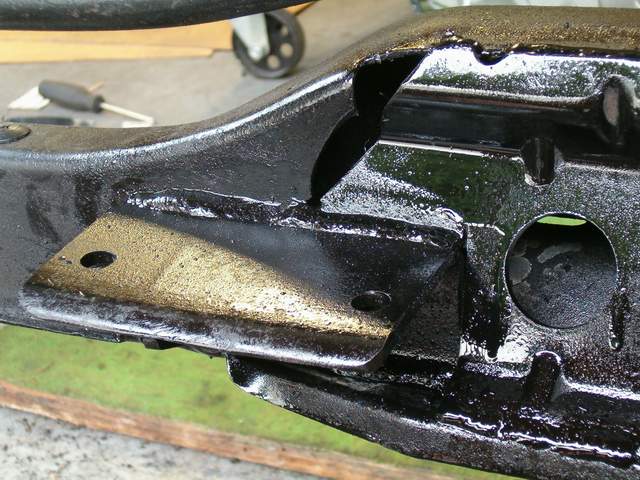
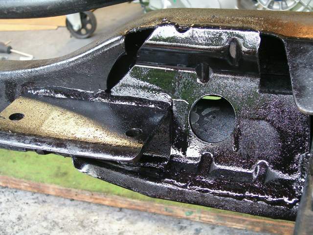
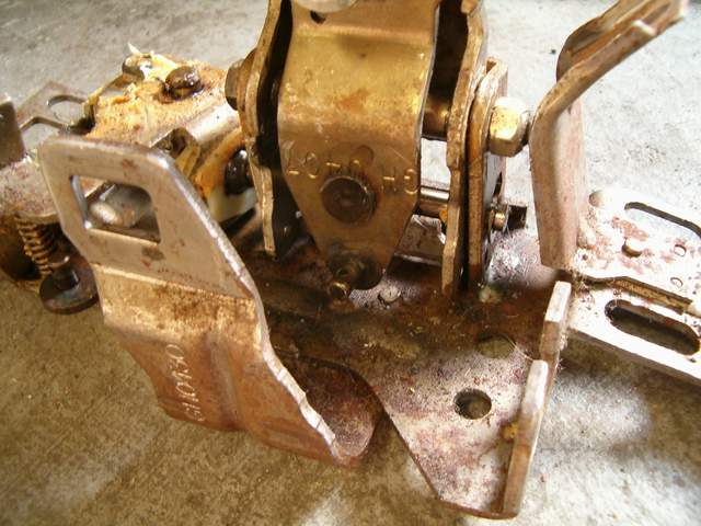
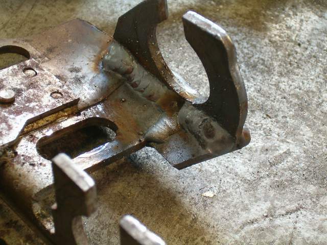
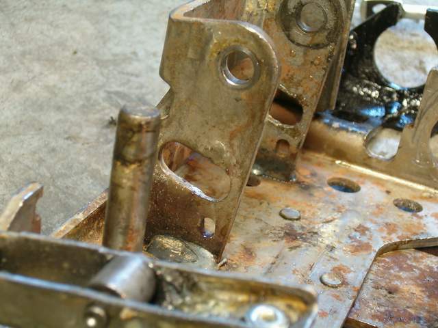
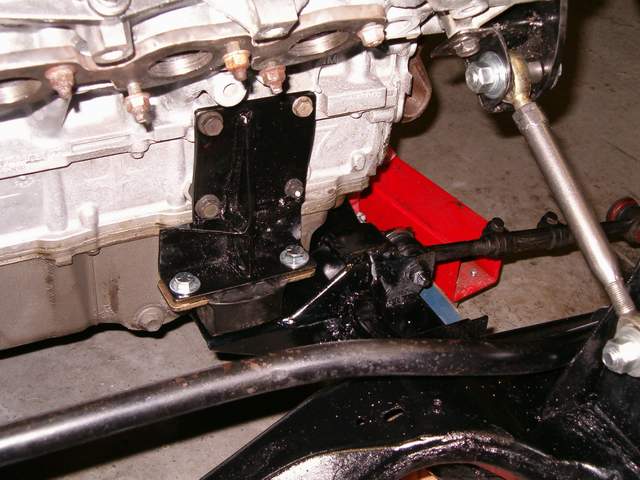
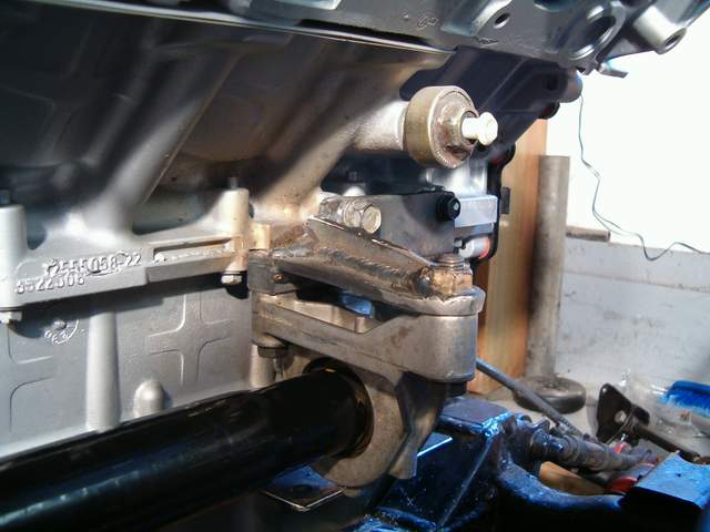
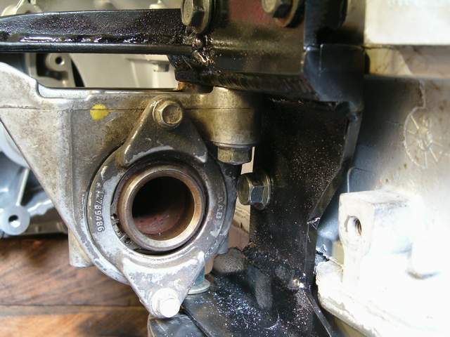
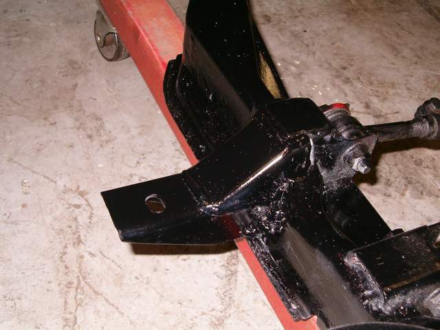
My original engine mount i had made while using the getrag wasn't going to work. It was in the way of the intermediate shaft and the cv axle. You can see the original mount and location here.
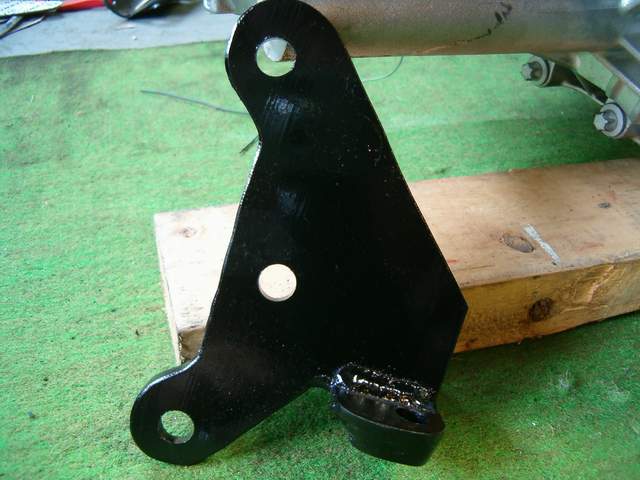
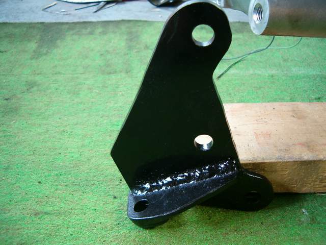
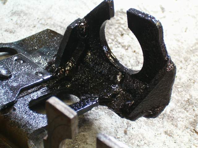
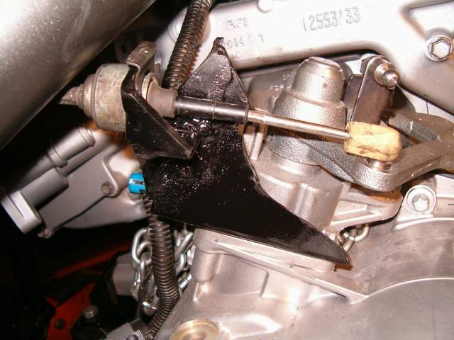
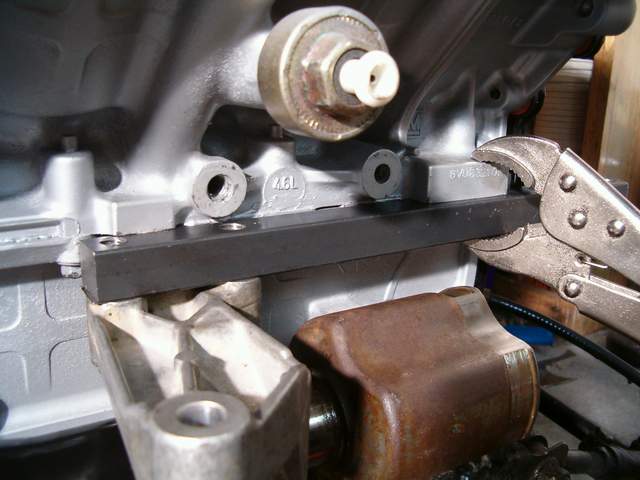
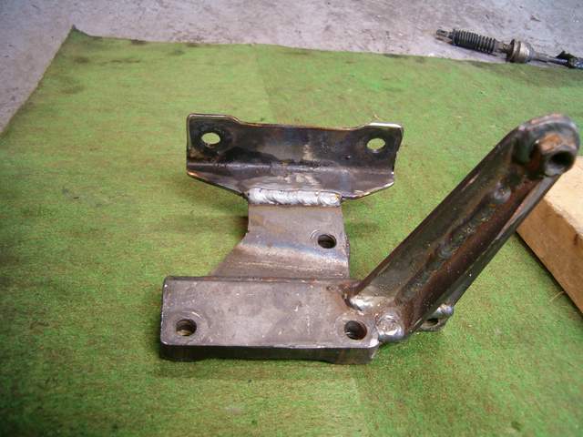
The intermediate shaft bearing is in almost the exact same area so i had to find a way to encorporate both the engine mount and bearing support into one piece. It turned out pretty good and i'm happy with it, only downside is it's fairly heavy, probably 2 lbs or so, hahaha. As stated before the intermediate shaft that i am using is from an 05 cobalt SS supercharged. I started off by drilling and tapping two holes 1.875" apart into .75" solid square stock. I then bolted this to the intermediate shaft and found that if you could clamp it with vice grips to the block it lined the shaft right up and would spin easily.
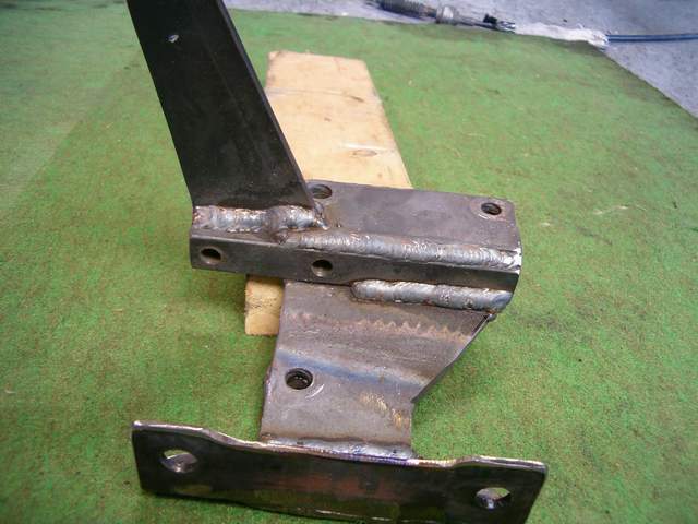
I then made a plate for the top to bolt holes and spacers to weld on the backside to space it out the required distance. I tacked and welded this on and made a plate with a slight bend in it to run down to the lower bolt and the footing for the engine mount. I tacked that on aswell as the footing. Then i made a plate to extend to singular bearing bolt hole and bolted this in place. I tacked this in place as well as a gusset to run along the top. Removed everything and welded it up. I cleaned it up with a little trimming and grinding and painted it.
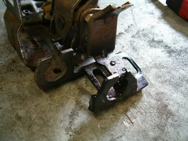
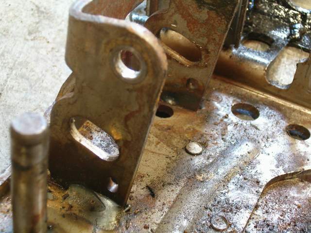
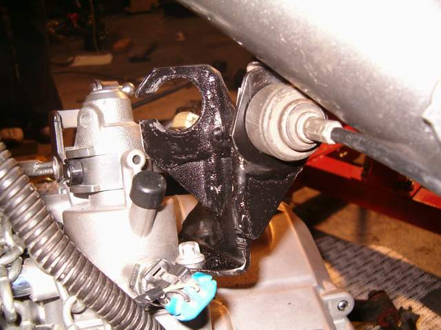
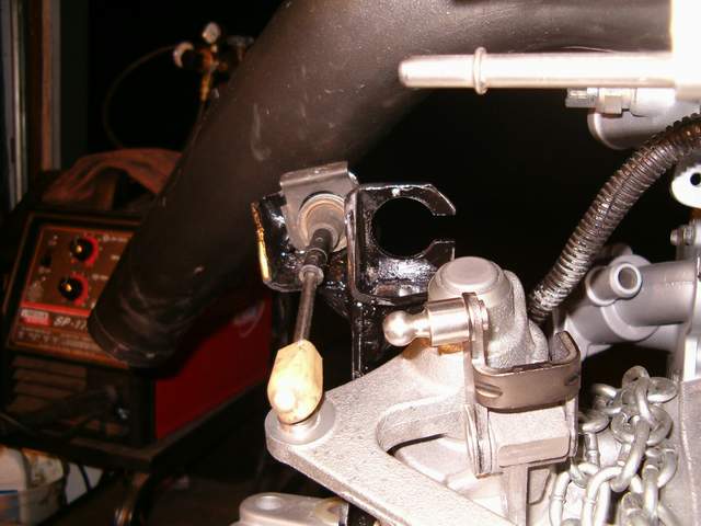
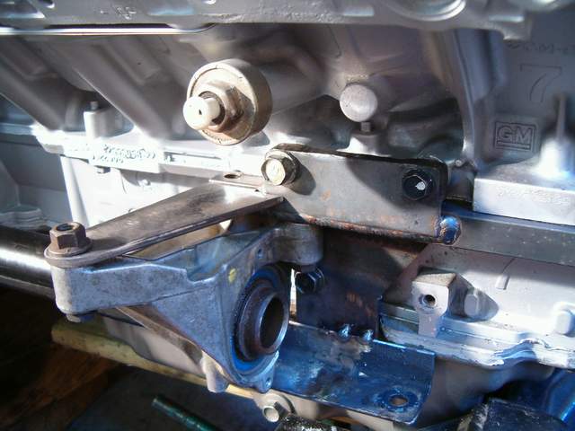
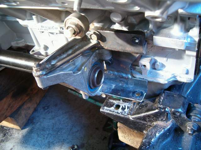
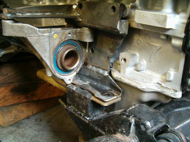
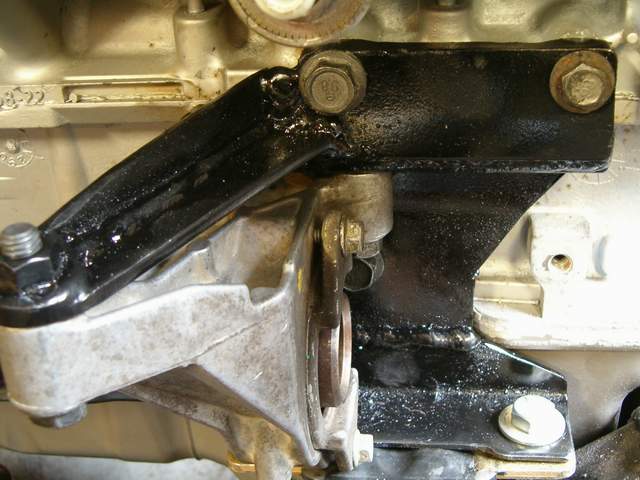
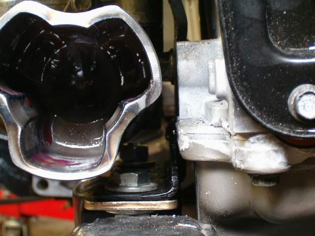
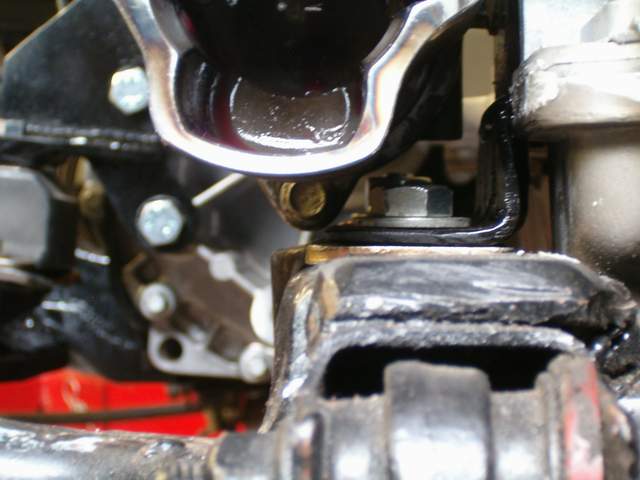
There are a couple of tricks to putting it in because the area is so confined. The mount has to go in after the intermediate shaft is in place and the intermediate shaft must be bolted to the mount before the lower engine mount bolt can go in. The bearing cap must also be removed before the lower bolt can go in and I am limited to using an open end wrench to tighten it. Here you can see some of the tight clearances in between the mount, intermediate shaft, and cv end.
The good news is that aside from the flywheel adapter and axles, all of the tricky parts of the swap are pretty well done. IT CAN BE DONE!, wohoo. One small clearance issue to take note of is after the axles come together and the bands are crimped arouned the cv boots, the nub formed by crimping is large enough it will interfere with the block. Pound the nub flat with a hammer and all should be good.
I didn't bother checking both forward and backward stops on the shifter. When I noticed I needed more travel for the even gears I cut the stop for the shifter, but if I understand what you did correctly I apparently had more forward travel than what was necessary in which case I could have gone to my bracket at the tranny instead, realizing how iffy things can get I made my bracket for the cables at the transmission adjustable so I probably could have loosened the gear select mount and moved it to the appropriate location. I still have the extra shift lever from the 5 spd shifter I butchered, especially since the stop removal allows for a little shaky feel when selecting the even gears and if you are not careful slamming a gear or two may damage the cable since it would absorb all of the stopping force.
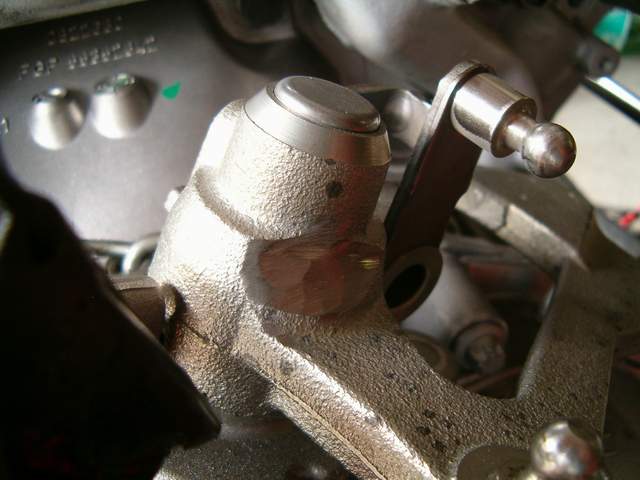
OK, so i decided i wasn't entirely happy with my shifter. When slamming it back into an even gear (2-4-6) it would stop on the cupped end of the shifter cable on the tranny, not a big deal. But when i slammed it into an odd gear (R-1-3-5) the cable would be close to it's limit of travel and kink at the end. That i decided should definatly be corrected, and while i'm in there i might as well fix the other stop too. So basically i just welded a 3/16" thick tab infront of the original pin for the odd gear stop and then built the weld up and used that for the even gear stop as seen here. Works like a charm, no more kinks and no bottoming out. Perfect!
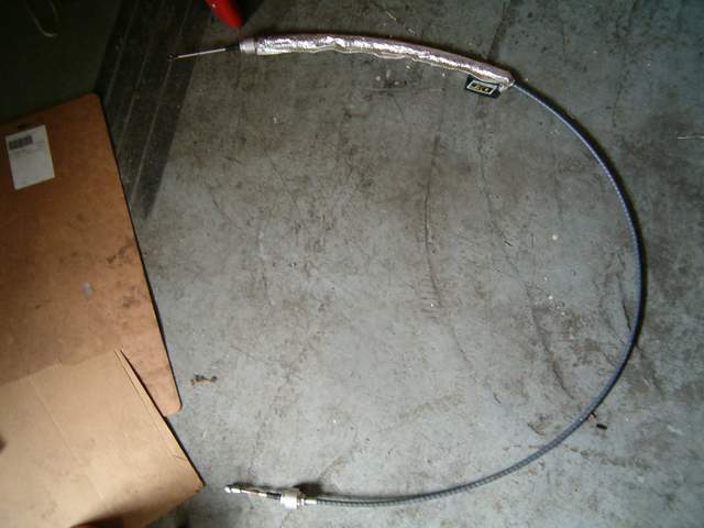
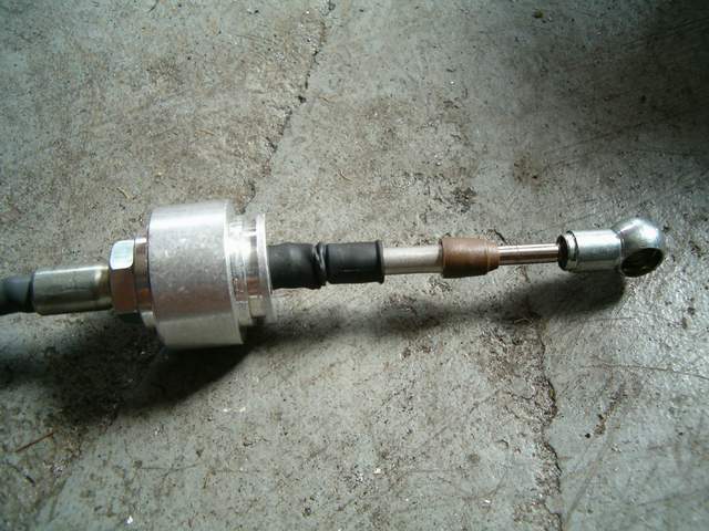
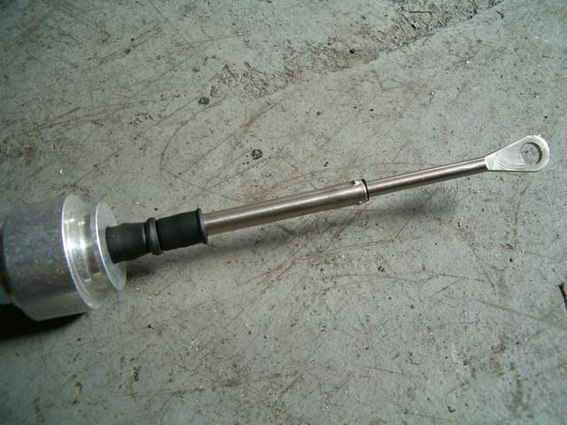
I got my select cable from the fiero store today. Looks and feels really good. Only problem is the transmission end has a slightly different guide tube on the end and was contacting the shifter on the transmission when trying to pull it into the reverse gate.
Simple fix was just to grind a little bit of a releaf into the shifter part.
The other strange thing is that the cupped trasmission end of the cable came with a dollop of grease inside it, but mixed in with the grease were a bunch of metal shavings, like swarf from drilling! Just goes to show you should always inspect everything you buy very carefully no matter what it is.
Well i take 1 step forward and ten steps back. i bolted on my struts/spindles today to double check my calculated measurement for axle length and low and behold, the axles don't F***ING line up. A crutial measurement that i assumed to be the same was the distance from the input shaft to the axle splines, this turns out to be different. So now i have to redo all of the engine mounts and make a new dogbone to move the engine back 1 inch. I sure hope theres room in the engine bay for that it was pretty tight before. I'm sooo pissed right now.
On second thought, moving the engine back 1 inch would require all new engine mounts, new dogbone, possible interference with the power steering pump pulley and strut tower, possible interference between rear head and firewall, I am making new headers anyway but the old ones would not line up anymore. I would also have to make a new cold air intake tube, and the decklid strut would probably cause an issue as well. Basically everything i did to get the northstar in there originally would have to be changed and i'm not prepared to do that much grinding, welding and fabrication all over again. With the shortest axle being probably somewhere around 10" between pivots and a 1" offset thats less that 6* equivelant steering angle. I've decided i'll just let the cv axle take up the angle since i dont think 6* is to big of a deal. If the cv wears out a little quicker than if it were straight, big deal, it's a hell of a lot easier to change one of those every 5-10 years than remaking everything.
Some will say that the axles need to be perfectly aligned, but I tend to disagree. Your 1" offset to the front is the same as if someone lowered their car 1". With all the lowered Fieros running around, there has not been a huge rash of CV failures on the lowered cars. Not all CV's are created equally, but the front axles on a chevy 4x4 run at a significantly greater angle than 6 degrees from factory.
What is the distance from the crank centerline to the center of the front cradle bolt? My halfshafts are also at an angle to the front, the car is lowered about an inch, and the engine is lowered within the chassis, so my halfshafts could be at a slightly larger angle (never measured it), but they have been that way behind a SBC for 20,000 miles without any issues (and 5K of that was puliing a 1000 lb trailer).
Well i take 1 step forward and ten steps back. i bolted on my struts/spindles today to double check my calculated measurement for axle length and low and behold, the axles don't F***ING line up. A crutial measurement that i assumed to be the same was the distance from the input shaft to the axle splines, this turns out to be different. So now i have to redo all of the engine mounts and make a new dogbone to move the engine back 1 inch. I sure hope theres room in the engine bay for that it was pretty tight before. I'm sooo pissed right now.
Sorry to hear that, I know the feeling when it isn't right and there is no option aside from cutting and welding after you've done so much of it already. I used the shift cable from the 4 spd muncie from advance auto on my 6 speed, I didn't know of any other options used on the Fiero that had the proper ball cup size. Is there no way you can cut the mounts in two and weld them back together offset?
Modding the tranny mounts for an inch backwards wouldn't be that bad but the engine mounts would be trouble, ecspecially the frame part of the rear engine mount because of where it is and the shape of it. Plus the engine would have to be raised for the oil pan and tranny to clear the suspension mounts. The more i think about it the less concerned i'm becoming, I think it will turn out allright. Joseph, i used 2 getrag 5 speed select cables, proper cup size and they're quite long so they're not an issue routing around the bohemouth N*. When i had the 5spd tranny in there the select cable was fine but the shift cable had to be re-routed to go through the original select cable hole in the firewall to get it closer to the tranny. It was a real tight fit over the top of the head and onto the 5 speed. But with two select cables and the different bracket geometry it should be great. I'd like to see the difference in length between one of the cables you used and one that i used.
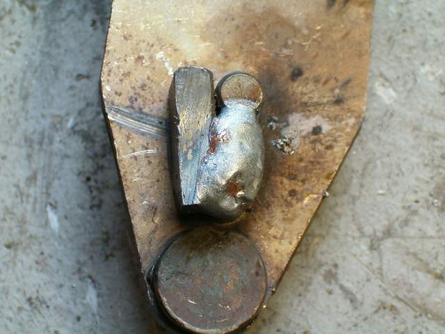
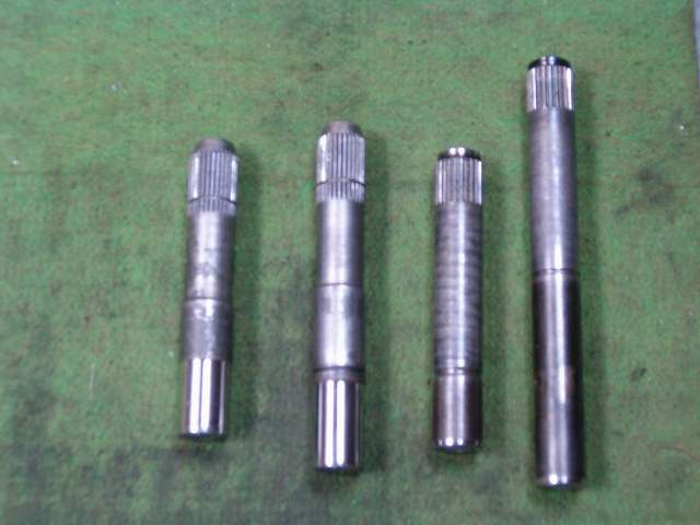
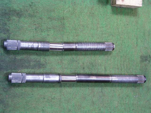
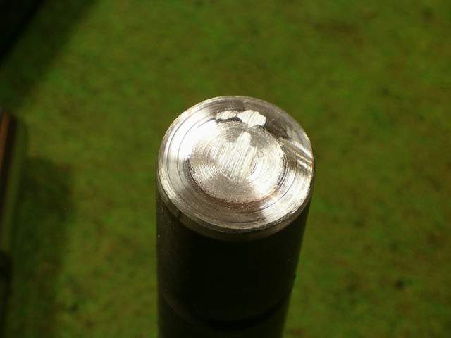
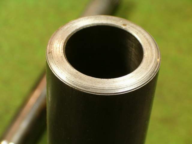
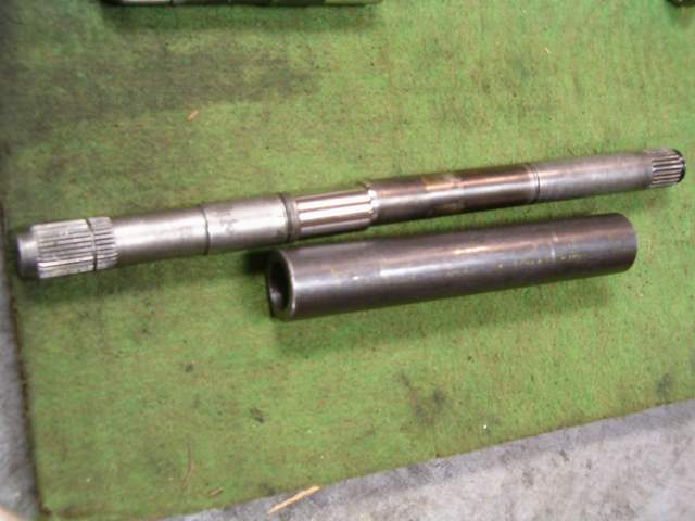
I have the axles ready to attach somehow. I will post the exact lengths once they're together and i know they'll work. I'm not sure how i'm going to put them together yet. They are about a .005" press fit into a 1/4" wall hydraulic tubing sleeve. The tubing itself should be strong enough considering that torsional strength increases to the 4th power with radius. I figure that even with the metal compositions being different the tubing should transmit 2-3 times more torque before breaking than the solid 1" axles. I'd like to try and not distrub the temper in the axles, they are hardened about 1/4" deep as you can see in the pictures. I'm not sure if i should press them together and rely on the friction fit to transmit the torque or press them together and weld them at both ends. If i just rely on the friction and then do spin then they might spin weld in place and could become stronger than just a bead around the outer edge. I'll have to look more into this and start another thread about spin/inertial welding and friction fits.
There have been a few that have tried welding axle shafts in the past, and they never followed up on their results. This most likely means that they succeeded, but I would like to see that its a proven method, as it is significantly easier trying to get axles in these 6speeds.
Edit, Would it be possible to get some splines cut into both the "tube" and the axles? Instead of a pressed juncture, why not have a pressed, splined, welded juncture?
[This message has been edited by darkhorizon (edited 10-10-2007).]
You could drill a couple of holes in the sleeve, assemble the axles and then plug weld the axle to the sleeve to ensure they do not spin. The press fit would help lessen the torque the welds and area around the welds would experience.
Originally posted by darkhorizon: Edit, Would it be possible to get some splines cut into both the "tube" and the axles? Instead of a pressed juncture, why not have a pressed, splined, welded juncture?
A spline would be the best in this situation, but if machining a spline was a possibility than i would have just cut the shaft to the right length and remachined the spline for the inner tripot assembly. Unfortunatly this whole process is to get around the machining of splines. (i dont mean to sound sarcastic or anything, that truly would be the best way to attach the collar) I have a feeling that i'll end up welding them, but if i do i will be sure to document the abuse that i put them through and if they hold up.


 and if they hold up.


