A little more work on wiring up the Fiero BCM & Riveria digital IC into my 86GT.
While wiring up my terminal strip "B" I run across a potential issues with the "Headlights Suggested" and "Headlight On" sensors! I am not sure if the Headlights on indicator would cancel out the "Headlights Suggested" indicator. I checked with Chris Eddy, the developer of the Fiero BCM module and he could not say for certain of the operation. So this will require me to go an retrieve my Riviera digital IC from the shop that is cutting out the new face plate for the IC.
Once I figure out what course of action that needs to be taken I will get back and report what I have done to resolve the potential issue.
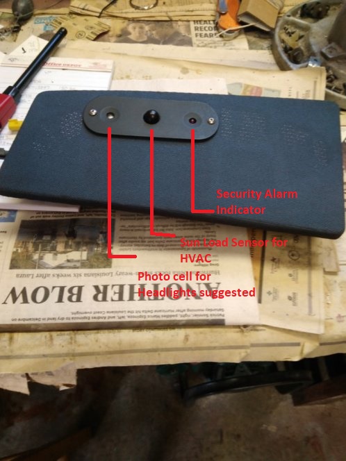
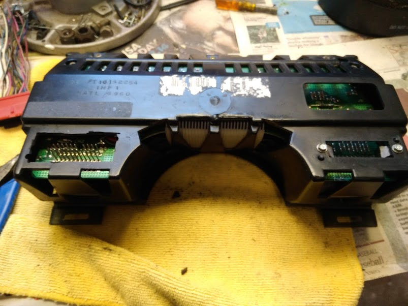
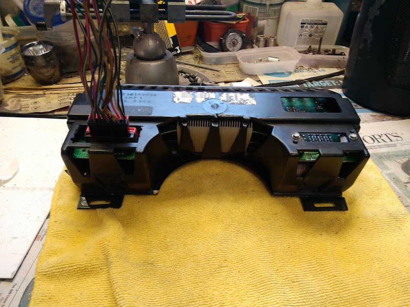
This is what the dash senor panel looks like:
As you can see the panel contains 2 sensors and 1 indicator. The dash panel is from a 2001 Grand Prix. The sun load sensor is part of the digital HVAC system that I have installed in my 86GT.
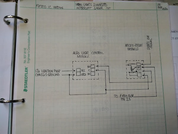
Let's see if this works, trying ANOTHER file sharing service. This is the wiring diagram for installing the Riviera IC and the BCM into a Fiero. Let us know if you see something missing or wrong.. Link to Wiring Diagram
Due to the weather I was able to do some work on finishing up the wiring on the Riviera digital IC, Fiero BCM wiring and not do home repairs. I am happy to report that the wiring is near completion. What remains is the cleaning up of the wiring placement, installing the Riviera IC for testing in the new wiring configuration (the fun part). My plan is to install the Riviera IC & Fiero surround where it is suppose to go with the dash being in place. I am do it this way for ease of correcting and wiring adjustments that may be required and to ensure that I don't have a short or anything like that.
Oh, Chris..... your wiring link works!!
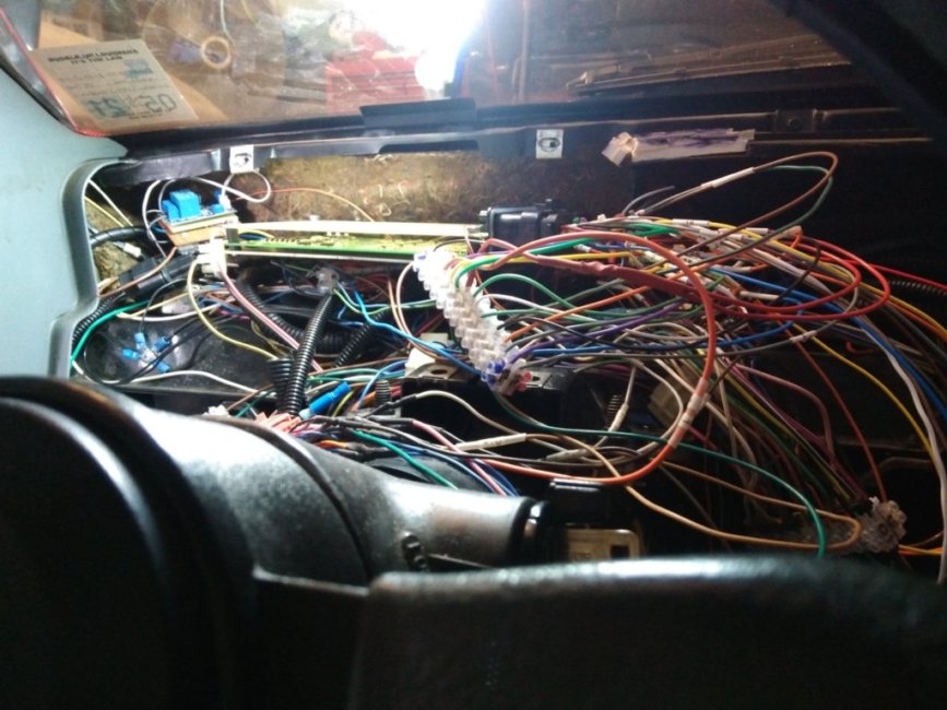
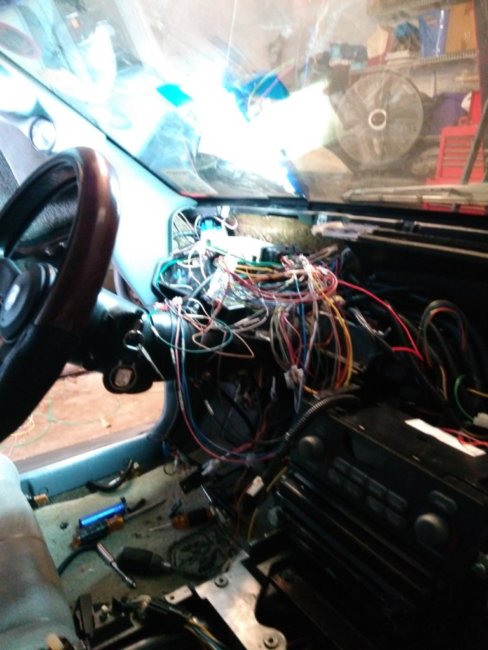
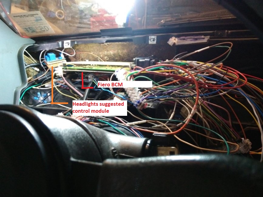
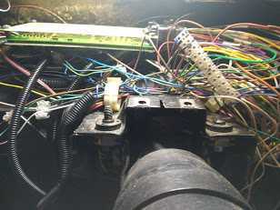
Photos of the finished wiring, not cleaned up! I know, it looks like a big ass rat nest.
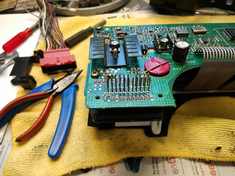
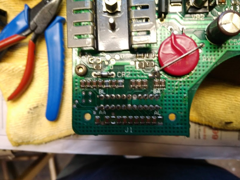
In addition, I have changed my photo cell controller for a smaller unit (space limitations). This control unit for the "Headlights Suggested indicator. Also, I added a micro relay to the circuit to cancel the "Headlights Suggested" signal when the headlights are in the "ON" position.
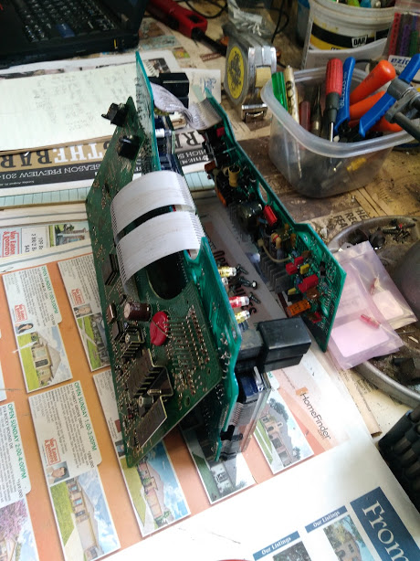
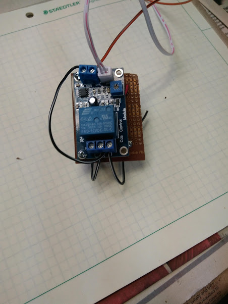
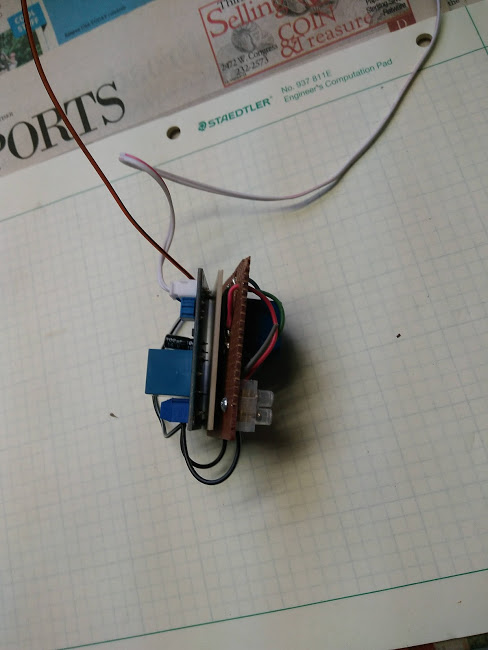
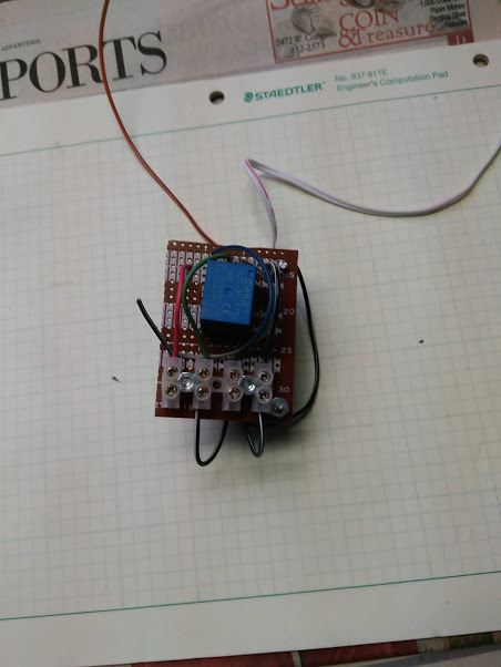
Below are photos of the Light controller circuit board:
Photo of the wiring diagram:
I will have to make a trip to the shop that has my Riviera digital IC. They are the ones that will be cutting the new face place for the IC. Unfortunately, they are closed until the 2nd for the holidays. Oh well........
Once I have the Riviera IC install I will post photos of that..........
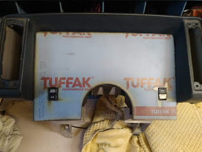
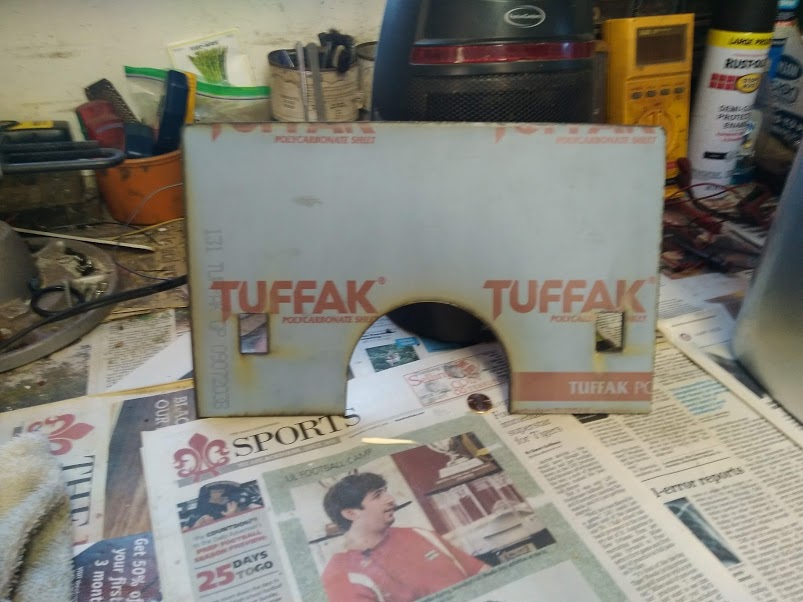
Finally got the IC face plate from the shop & the instrument cluster/surround! The new face plate fits perfectly, but a little long. I had forgotten to measure up the face plate with the bottom Fiero instrument cover in place when I was measuring up the face plate dimensions. Oh, well.... luckily that's an easy fix.
Having said that I noticed that the size face plate (Lexan) I used was too thick (1/8") or in my opinion is too thick. It appears that a 1/16" face plate thickness would be better. That is now on order. My plan is to go ahead an installed the Riviera digital IC & Fiero surround into the car and begin testing the unit to ensure there are no issues. If there are I will correct as I come across those problems.
Sorry for the delay, but hey this in unchartered territory!!
Here is a photo of the new face plate and the surround:
I worked as a EE myself and must say this is quite a complex project. I lean toward analog but can appreciate the work that went into this project. Your Fiero dash will look very unique. The only suggestion that I would make is to make sure you have a spare LCD panel just in case part of the installed panel ever burns out.
------------------ " THE BLACK PARALYZER" -87GT 3800SC Series III engine, custom ZZP /Frozen Boost Intercooler setup, 3.4" Pulley, Northstar TB, LS1 MAF, 3" Spintech/Hedman Exhaust, P-log Manifold, Autolite 104's, MSD wires, Custom CAI, 4T65eHD w. custom axles, Champion Radiator, S10 Brake Booster, HP Tuners VCM Suite. "THE COLUSSUS" 87GT - ALL OUT 3.4L Turbocharged engine, Garrett Hybrid Turbo, MSD ign., modified TH125H " ON THE LOOSE WITHOUT THE JUICE "
At one point I did some searching for LCD displays that could be used to retrofit a Fiero IC bucket. But alas, the hard part is finding a round LCD display of the right dimensions. And rectangles just did not want to fit right. That would be fun to do. And the Vac fluorescent displays in the Riviera IC are super custom, so you would have to have them made special. You are right Dennis, word is that the Riviera IC has a failure mode from overheating.
Thanks Dennis & Chris for the comments. I have heard about the Riviera digital IC have possible issues with heat. For that reason I plan to place a cooling fan behind the IC. Not sure if that will address the problem or not but will give it a try. Point well taken about the need to have a back up IC. I have a second and plan on getting another shortly. The local Pull-a-Part sent me a notification they had received a '89 Riviera. Plan on going next week to check it out.
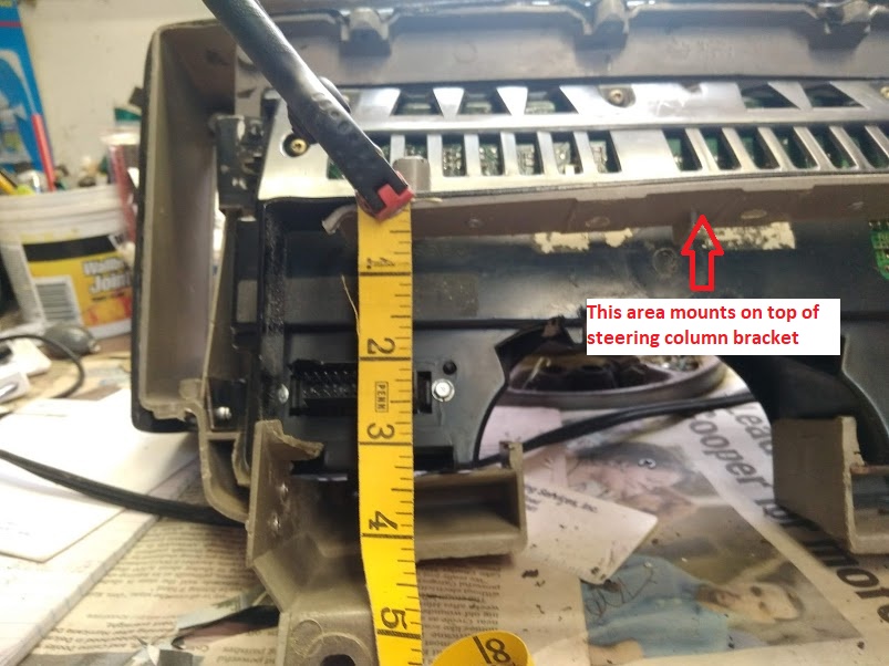
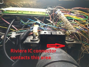
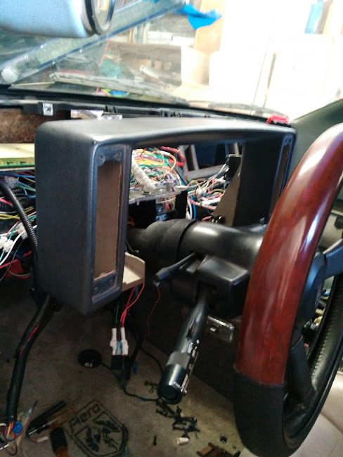
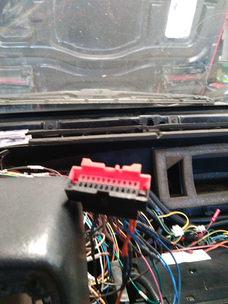
I am currently in the process of installing the Fiero surround with the Riviera digital IC into my 86. A couple major installation issues has arisen that will need to be addressed before I can move forward. The main issue is the Riviera digital IC rear connector is hitting up against the right side of the steering column mounting bracket. Since the steering column bracket cannot be relocated or removed the Riviera IC connector will have to be relocated. That is what I am currently working on. Relocating a fixed connector is not an easy task!
I do have a game plan and will be working on the relocation of the connector.
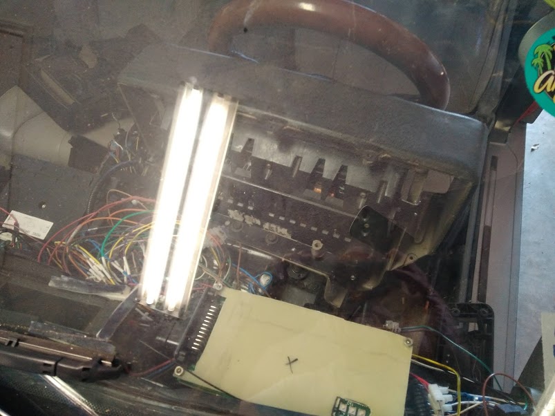
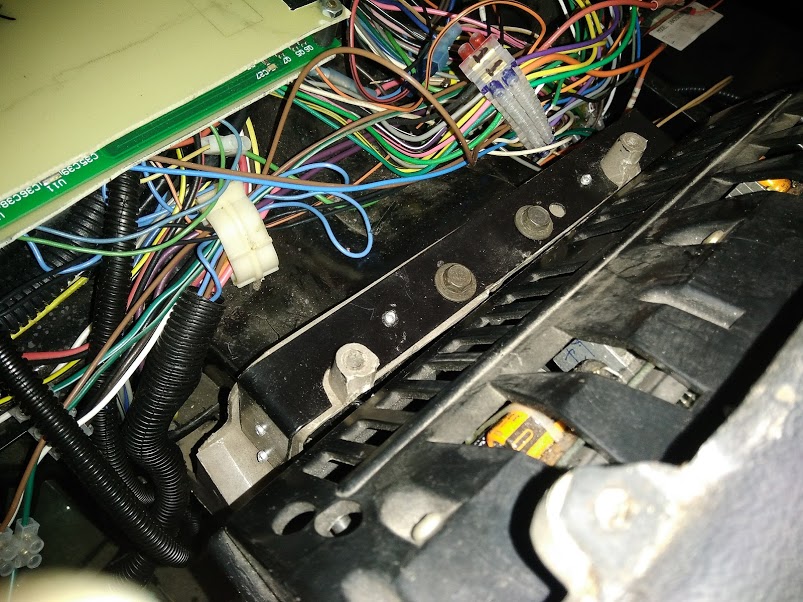
This is the steering column bracket in question:
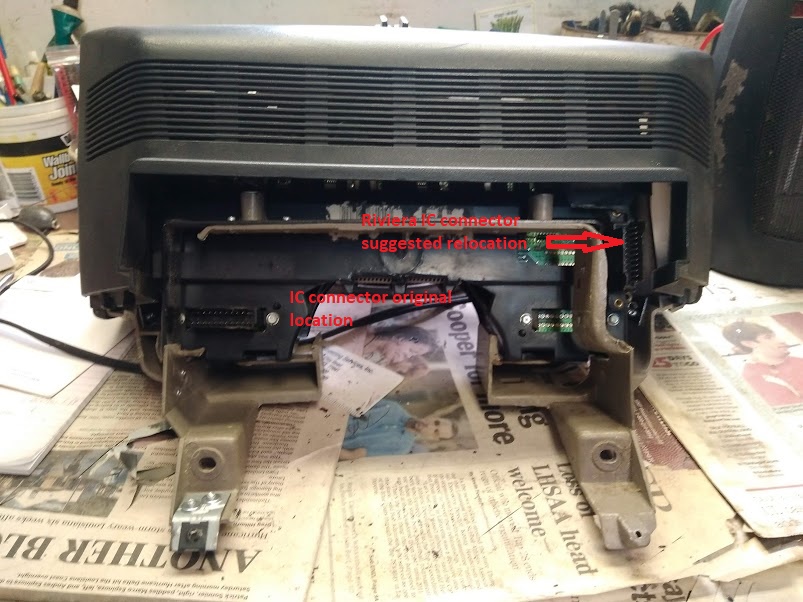
Fiero surround mounting location & IC connector location:
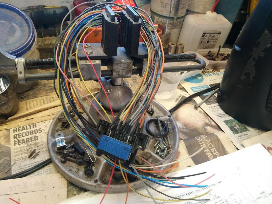
I have removed the rear connector from the spare (inop) Riviera digital IC. I am basically just testing how best to relocate the rear connector for final installation. Also testing how best to remove the connector pins that mate to the Riviera IC circuit board. For my case it would appear the best and perhaps easiest method is to heat the pins then remove when they become mobile. That is the method I will be using. Once the connector is removed I plan drill out the connector pin locations on the circuit board to facilitate the wire pigtail installation. If anyone has a better suggestion please do so!
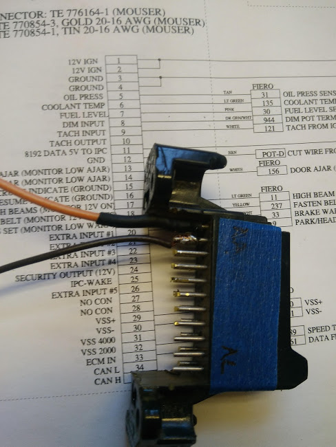
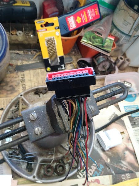
I have begun wiring up the removed connector. I hope to follow the OEM wiring color code for the connector pigtail wiring as close as possible. Starting the rear connector wiring mods:
Once the wiring of the rear connector is completed I will post another photo of the completed wiring job.
Cajun, a comment and a question.. First, I would not drill the holes to put the wires into the circuit board. The holes are plated through, and if you drill them the soldering on top and bottom would have to be just right, and prone to failure. Question, is it possible to shift the IC up, or forward, or both? I for one have to sit up and peer over the steering wheel to see the gauges. So a little up and forward might not be a bad thing. Instead of the original connector from the IC, you can now choose a different male and female connector to work with instead.. something with crimped pins would be great.
Thanks for your comments: Item 1: On drilling holes, I was referring to drilling out the solder on the mounted connector point once it was removed. Basically cleaning up the connection point. Currently thinking the drilling would require additional work and potentially cause other issues. My current plan is to solder wires to connector pins on the IC circuit board.
Item 2: Relocating the IC & surround. I am thinking that would open up a linty of new mounting issues. As it currently stands the Riviera digital IC fits pretty snuggly in the Fiero IC surround. Moving the surround up a bit would then require new fitment issues regarding the surround and mating components. It's doable but would require additional work and fabrication of companion components to make it look like it belongs in the new position on the dash. The IC could be moved forward a bit but not enough to allow the connector to fit. There is not really that much room for play or movement.
Worked a little on the Riviera digital IC rear connector modifications:
I have completed the pig tail portion of the Riviera IC rear connector modifications. Now for the real work! I also need to gather up enough courage to cut off the rear connector on a working Riviera digital IC. Once the rear connect is removed (cut off) I am pretty much committed to carry on. I just have not yet decided the best method for the removal of the rear connector. The pig tail section connector was cut off from a non-functional Riviera digital IC. I am leaning to that approach for the connector removal. Then I can remove the connector pins individually from the circuit board.
A photo of the pig tail section of the rear connector:
More than likely will not be doing any more work on the this project until after Christmas.
I have been dreading removing the fixed connector on the Riviera digital IC. To that end I have been researching my opinions and believe me there are not many!
HOLD Da PHONE.......... have you ever had one of those aha moments when the light bulb goes off in your brain to a potential solution to a problem? My fear was the removal of the fix connector on the Riviera digital IC for connection to the rest of the vehicle. The way I removed the one that I will possibly use for my solution for the existing IC connector contacting the steering wheel mounting bracket was to cut it out with a Dremel cutting wheel. That approach worked out okay for it's intended use or purpose but not so much the removal of the fixed connector on a working IC. I'm thinking the cutting wheel action could potentially create static electricity and fry the circuit board to which it is attached?
So, I have ordered a couple pairs of micro diagonal wire cutters. The wire cutters will be used to cut the connecting pins between the circuit board and the fixed connector. There is about an inch of play or room there. If all goes well I will end up with pins sticking up from the circuit board. Those pins and their placement appear to match the mating connector for the IC. If that is the case, we will be home free on this part of the project. Cross your fingers!! Failing this approach I will go ahead and wire each pin individual to the pig tail I have already fabricated. Not my first choice.
Once the micro wire cutters arrive I will proceed with the project. Also I will take photos of what we are looking at and the end results.
In fact it's a method that will allow most individuals to accomplish this modification to the Riviera digital IC. No soldering necessary!
The operation is to remove the IC rear connector to gain access for the installation of the IC in the Fiero surround. By removing the connector an inch or two of clearance is gained for installation of the Riviera digital IC into the Fiero surround.
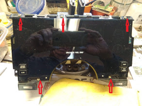
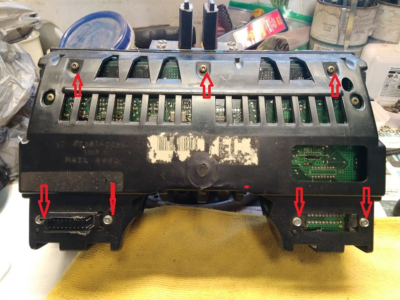
To access the IC connector & the circuit board the front and rear covers will need to be removed. To remove the covers 12 screws will need to be removed. Five Trox T-15 and three Trox T-15 and four 7/16 hex screws in the rear.
Once the rear cover is removed and you have clear access to the connector you will need to cut the pins coming from the IC circuit board to connector. Cut the pins just below the connector. I found it's best to cut the pins with micro diagonal wire cutter. The head of a micro wire cutter allows access to the individual wires (pins) from the circuit board. You will notice that in cutting the pins some may bend slightly in the cutting process. No worry, they can easily be straightened once the connector is removed.
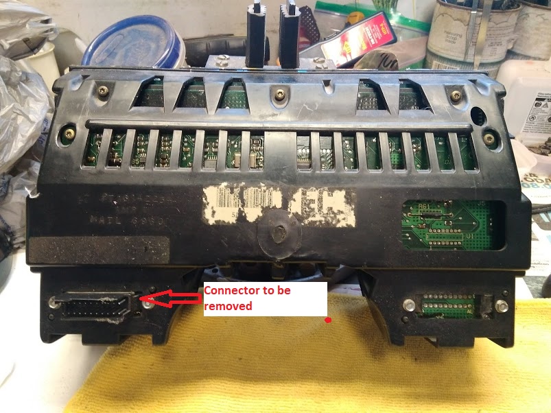
This is what the circuit board should look like once the connector is removed. Oh, it was a ***** to removed the screws attaching the connector to the circuit board.
The opening where the connector was will need to enlarged to accommodate the IC mating connector.
Photo of the mating connector installed. A note of caution when installing the mating connector ensure you have the proper connector orientation. The pin numbers are marked on the circuit board to aid in connector orientation.
I have not yet re-installed the surround back into my GT. I will follow up once the surround is installed.
I have installed the Fiero surround in my GT for a test fit:
I then removed the surround, installed the Riviera digital IC and re-installed in the GT:
The following photos are various shots to the installed, back & top views. Sorry for the overhead light reflections in some of the photos: Back view:
Top view:
In order to gain additional room for the Riviera IC connector I had to shave the lip off of the connector. I will be the first to admit the fit is tight but manageable.
Stock Riviera digital IC rear connector:
The Riviera digital IC rear connector shaved:
I have not yet powered up anything. Before that can happen I need to re-install the various connectors and switches that was removed previously. I will not be re-installing the dash until I can test the Riviera digital IC. Don't want to have to do work twice or three time before I get it correct.
Powered up i Riviera digital IC this afternoon. Nothing happened, so I am pulling g the IC to see what went wrong. Suspect there may be a wiring error in my part?
Went through a few electrical checks to see what I could have possibly done wrong? I removed the Riviera IC and disconnected from the car. I then connected a mating connector in order to check the various signals from the connector. All appeared to be good with the static checks; checked the various power pins and ground pins to ensure they were responding as planned.
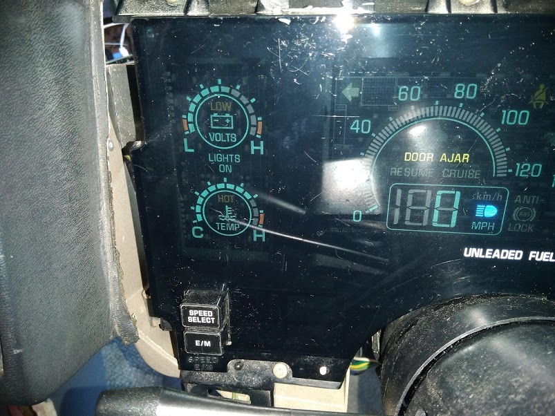
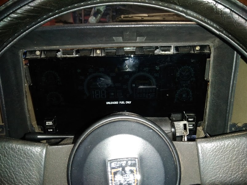
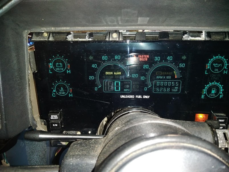
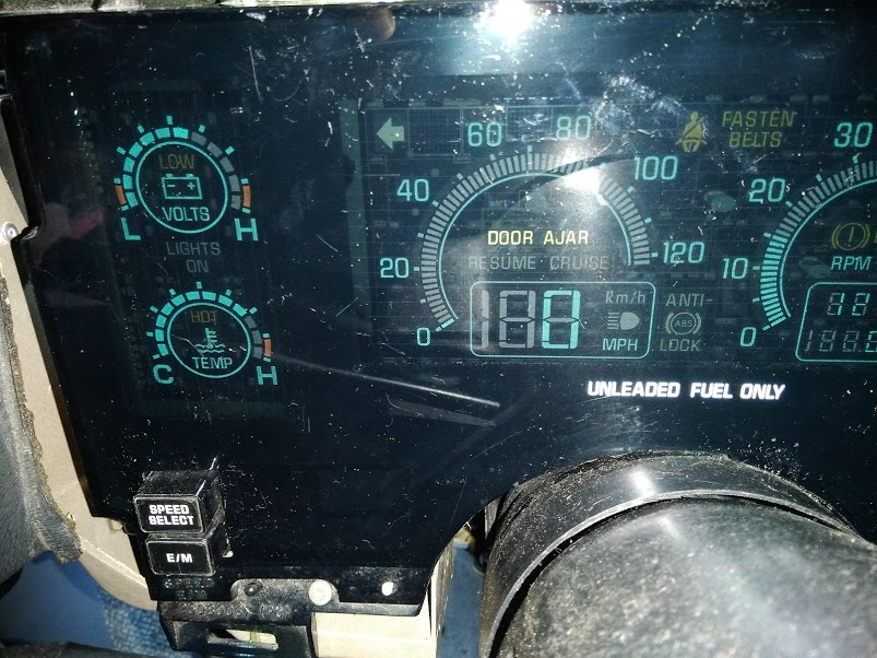
It turns out that I have not seated the mating IC connector all the way. Once I reseated the connector and powered up. The IC lite up!!!! I made a few quick checks to see if things were working. I.e. turn signals, hand brake, door ajar, etc. Those items appear to be functioning properly. I did start the car up. The voltage gage responded as did the temperature gage. The tack does not appear to be working?
I plan on doing more checks next week. But hey, making progress. My worst fears did not happen, smoking the IC during testing!
Here is a shot of the Riviera digital IC powered up in my GT.
I continue to test the various functions of the Rivera IC. I still have a few indicator functions to check out before I can say the testing is complete.
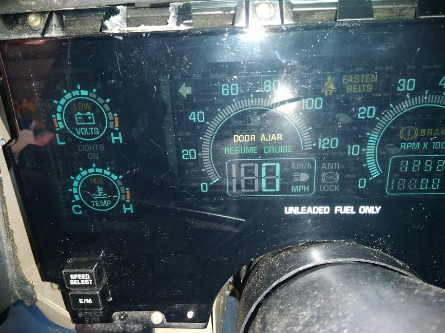
Here is what is working thus far: Turn signal indicators, emergency flasher, the gages (voltage, oil pressure, water temp and fuel level), seat belt indicator, Brake warning, cruise Resume, SES indicator, and tach.
My plans are to complete the Riviera IC testing by the end of next week, hopefully?
Photo of the IC working.......
In the above photo I was concentrating on the water temperature gage. The radiator fan started. In my mind the gage is reading a little high. When I have the Fiero stock IC in the car the temperature page never got above 200-210 degrees. I have a low temp switch installed.
This photo is where the radiator fan kicked off.
Hopefully next week I will attempt to verify the operation of the following indicators: Low Oil Level, Washer fluid, Low Coolant level, cruise Engage, Headlights suggested, Head light indicator, Security indicator.
Once all has been verified and checked I will put the GT on the road to check the speedometer function.
Just saw this thread. Your electronic skills are amazing. Few people would take on this kind of a project.
On a completely different note, I have the same instrument cluster as you. I got mine out of an early 90’s Riv. However, it went in to my Reatta. Did you know that quite a few Riv & Reatta instrument clusters suffer from the dreaded “00” error message? Trust me on this. . Also, I discovered that when you pull a Riv instrument cluster at a PickNPull, it is very wise to check all the bulbs! I have replaced quite a few.
By the way, I love the display but I HATE the stupid “headlights suggested” orange light. I hate it when my Reatta tells me what to do. I find it very annoying! I have asked my Reatta buddies how to disable it but alas, they said you can tell the car it is nighttime but that will only open up a can of worms. Kit
Kitskaboodle, thanks for the comments. Replacing all the incandescent bulbs was one of the first things I modified on the Riviera IC cluster. Replaced the incandescent bulbs with LEDs.
As far as the "Headlights Suggested" goes I have a circuit for that. When you power up the headlights it overrides the "Headlights Suggested" signal. Bare in mind that I am not using the Riviera BCM.
Did a little more testing of the Riviera digital IC today as the weather here in south Louisiana is spring like. Having said that, the weatherman is telling us that an Artic blaster will be hitting south Louisiana by the weekend. They are predicting a 50 to 60 degree shift in the temperature. Oouch.
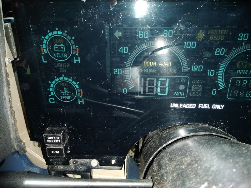
Here is a photo of the "Lights On" and "High beam" indicator powered:
A photo of the "Cruise" and "Resume" indicators powered:
I am having difficulties powering up the last four (4) indicators; the are "Low Coolant Level", "Washer Fluid", "Low Oil Level" and "Headlights Suggested".
I have contacted Chris Eddy to see if he has any ideas was to what the issues could be. In addition, I plan on purchasing a companion connector for the BCM so I can test it on a test jig. Don't feel like taking all the wiring down just to test the BCM.
[This message has been edited by Cajun (edited 02-10-2021).]
I am having difficulties powering up the last four (4) indicators; the are "Low Coolant Level", "Washer Fluid", "Low Oil Level" and "Headlights Suggested".
I have contacted Chris Eddy to see if he has any ideas was to what the issues could be. In addition, I plan on purchasing a companion connector for the BCM so I can test it on a test jig. Don't feel like taking all the wiring down just to test the BCM.
Do you have a washer fluid sensor now? If you do not have a sensor, it won't light up. There isn't a wire for low coolant from the Fiero either.
It was a matter of what to do with the icons on the cluster that had no corollary on our Fiero. So I just made an input to the BCM.. then if you want to modify or add a low coolant sensor, well, there is a place to plug it in. This input is "ground to activate". Some are not.. headlights on and left/right signal I believe are "12V to activate".
No real progress to report. I am still trying to sort out why four (4) indicators are not working? Also waiting on a response from Chris Eddy. Besides for the past ten (10) days or so my garage has been below the freezing mark. Too cold to do any real work.
Like you I am hoping to complete and wrap up this project in the next couple of weeks or so pending good warm weather (above 50 degrees). I want to move on to the next planned project; installing a 2008 3.5l Chevy engine and 4T65E transmission.
Now that the weather has warmed up a little I was able to perform more testing of the wiring for the Riviera digital IC and Fiero interface. Still trying to sort out why some of the indicator are not functioning.
Chris Eddy has suggested that perhaps some of my issues with various indicators not functioning was in part due to pins in the BCM connector was not seating properly. Yeap, that appears to be the problem. Now all of the various indicators are functioning as intended. They are: Coolant High Temp, Low Coolant Level, Washer Fluid Level, Low Oil Level, Headlights Suggested.
The only item yet to be tested is the speedometer. I hope to do that this week sometime? I have to get another face plate for the IC cut. The first one is a bit too thick, 1/8" the new one will be 1/16th. Then button up secure the wiring and re- install the dash, then hopefully I am done with this project?
On another note, I am toying with the idea of building another mating connector for the Fiero BCM. The one I built for the Fiero BCM was actually my first connector build, so it's far from perfect. I have ordered another companion connector. If I choose to do that it will delay completing the project a bit.
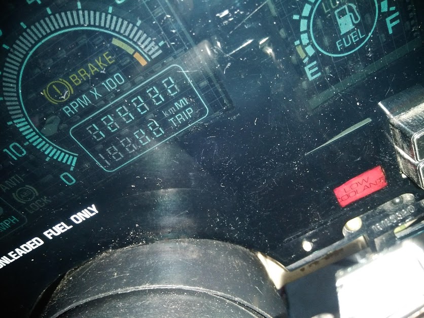
Photo of the "Low Coolant" indicator. The indicator is in the "A/C Service" position on the Riviera digital IC. Sorry for the poor quality of the photo, difficult to capture.
A couple of three set backs; 1. Several of the locking prongs on the pins in the connector have broken. They could be replaced but set back 2, the dash is too tight where all the wires are bunched up. This will require the relocation of the Fiero BCM. Rather than do a bunch of splices to lengthen the wire loom I have opted to replace the connector and associated wires.
Set back 3, the replacement connector I had ordered is not the correct companion connector for the BCM. I will have to order a replacement connector!
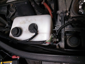
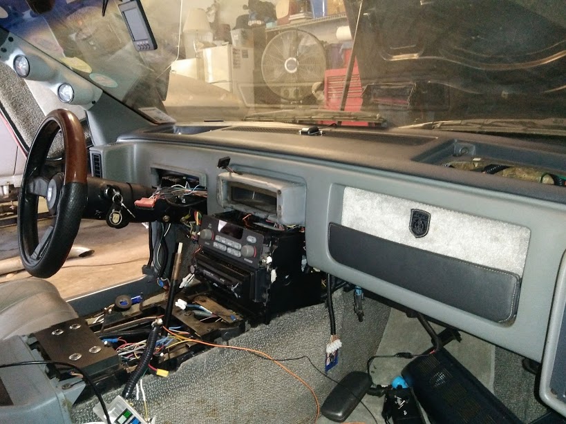
My plan is to relocate the Fiero BCM on the passenger side, somewhere around the "Blue Thingy" . There appears to be sufficient room there that would allow the placement of the BCM.
Ahoy mates, just a few things on the project.. Cajun, I used two different connectors on the PC board, a black one and a grey one. They have the same pins, but have slightly different keying in the plastic. I shooda stuck with one type, probably switched when I could not get the mate. Either way, I have my housing (the end with the wires on it) with a few slots cut in the plastic that lets me plug it into either one, so you might be able to do that. Cajun was questioning the correctness of the analog inputs (fuel, oil pressure, coolant temp), and sure enough, they needed work. The coolant temp is a thermistor, which is not a linear line, but a curve. Mike sent me the GM chart and I put it in the software. Also, the fuel and oil pressure calculations were improved (they was wrong). Meanwhile, I did a 14 minute video covering the testing of the inputs. In addition, I went on to show how the 3 setup buttons work and what they do. Link:: https://rumble.com/vekv9b-t...-use-in-a-fiero.html
No real progress lately. I have sent the Fiero BCM back to Chris Eddy for tuning?
The 35 pin connector and pig tails has not yet arrived (bummer). The shop indicated they would cut the new face plate next week if all goes well.
Once the items arrive I am waiting for it's pretty much just connecting everything up to the new connector, install the dash, done. Everything has been tested and works.
As previously mentioned, I will be locating the BCM on the right side of the dash in the area of the "Blue Dingy" thing. I am hoping this will ease up some congestion on the left side of the dash where the mini-terminal strips are located.
Chris, nice video. Now I understand how to operate the 3 switches. Thanks for that.
I finally received the connector with pigtails I thought I had ordered but to find I received only a connector and pins, no pigtails. I have gone back and forth with the supplier with no luck.
So, now I am in the process of building about 35pin connector with 3 foot pigtails. Once completed and tested I will begin installation.
[This message has been edited by Cajun (edited 04-10-2021).]
I received the re-programed Fiero BCM from Chris Eddy (The one I had that he recalibrated). I have re-installed it and was in the process of testing the BCM while I was building another 35-pin connector. While in the testing process I noticed that a couple indicator lights on the Riviera digital IC were no longer operative. It's my guess that they have burnt (incandescent lamps). These indicators are active a lot during the course of the IC operation.
I have removed the Fiero IC surround and Riviera digital IC in order to replace the indicator lamps that are not working. While at it I will go ahead and replace all the incandescent indicator bulbs with LED units. To replace the indicator lamps will require the dismantling of the Riviera IC. A time consuming process, not so much dismantling the Riviera IC but rather the replacement of the indicator lamps with LEDs. I will be using 74-A (Amber) & 74-R (Red) miniature Wedge Base LEDs from Superbrightleds.
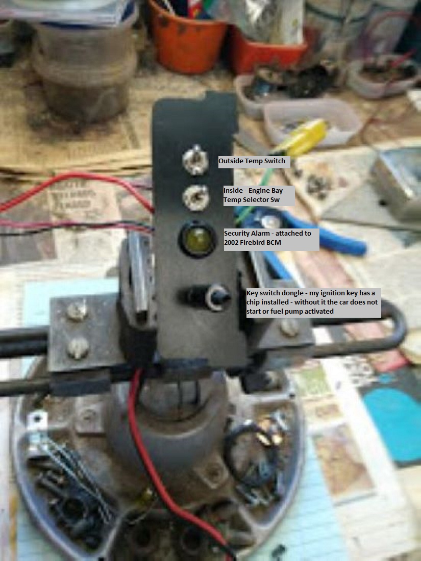
I have also updated my security system controller (attached to the 2002 Firebird BCM). Although not directly related to the Riviera digital IC install the Riviera IC does not have a Security indicator that I can attach to the Firebird BCM. This was a function that I had installed into my 86GT instrument cluster. All I did was add an indicator LED lamp for the "Security" function. Basically, when you install the key into the ignition switch the Security lamp lights up! If the dongle is not installed the car will not start or activate the fuel pump. The 2002 Firebird ignition key has a chip (specific value resistor) installed within the key. The dongle I built provides the function of the resistor key.
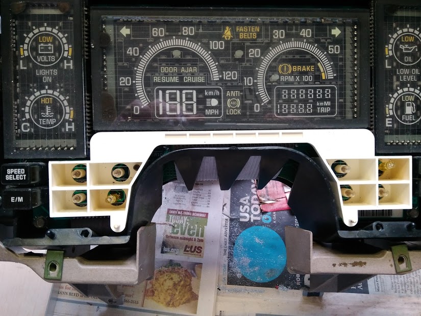
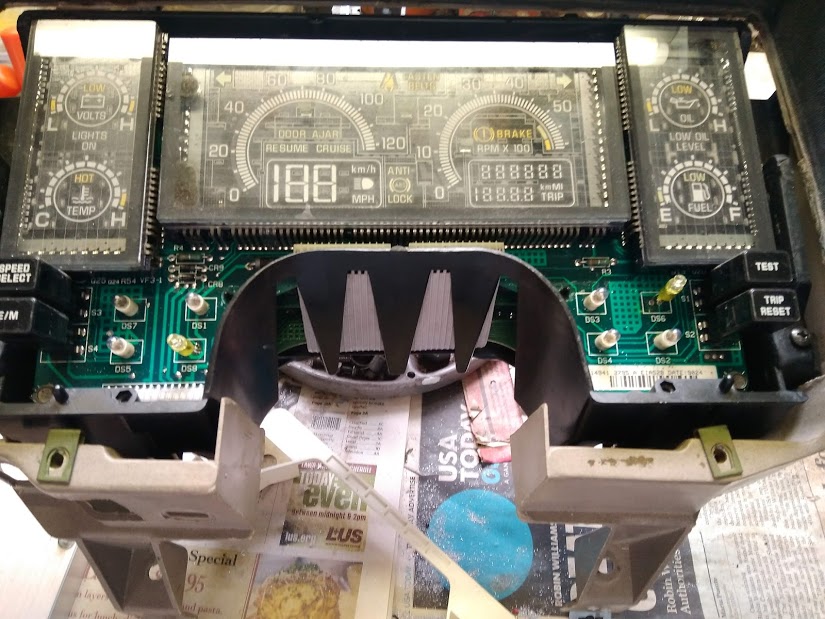
Here are a couple photos of the indicator lamps in question. As you can see I had already replaced a couple indicators that were burnt. Now for the rest of them!
This is so cool. I've always liked digital displays. I loved it in my 94 Town Car, I was a little disappointed that they went to a hybrid layout in the later Town Cars.
I have a Turbo Sunbird cluster (okay, two of them) that I want to try to put into mine because of the instrumentation on it, but this would become my next choice.
For folks with an automatic, what do you think the feasibility would be to have the RPM gauge be repurposed to be a boost gauge?
I really appreciate the work you put into this, especially with rebuilding it with the LEDs! Lower charge demands, less heat, longer life (depending on LED, of course), pretty cool stuff!
If there was ever an award given for the most complicated and technical instrument panel adaptation; it would have to be Chris project. As an EE myself I fully appreciate the large amount of R & D ,fabrication and the interface designs that were used here to get this dash functional. Outstanding A+ work.
------------------ " THE BLACK PARALYZER" -87GT 3800SC Series III engine, custom ZZP /Frozen Boost Intercooler setup, 3.4" Pulley, Northstar TB, LS1 MAF, 3" Spintech/Hedman Exhaust, P-log Manifold, Autolite 104's, MSD wires, Custom CAI, 4T65eHD w. custom axles, Champion Radiator, S10 Brake Booster, HP Tuners VCM Suite. "THE COLUSSUS" 87GT - ALL OUT 3.4L Turbocharged engine, Garrett Hybrid Turbo, MSD ign., modified TH125H " ON THE LOOSE WITHOUT THE JUICE "
Realized that I had not posted in a bit. Hopefully all can understand and appreciate the fact that life sometimes gets in the way of personal projects, especially when it comes to family!
The good news is that the dash is back in the GT. It took some doing to get it in, had to make about 4 or 5 attempts until the fit was correct. Had to reposition the wiring several times to clear the dash internal components. Now that is done I can move on to completing the replacement of the incandescent lamps in the Riviera digital IC. I have replaced 5 of 8. The amber LEDs are on back order.
Just for grins, here is a photo of the Riviera Digital IC disassembled:
I am getting close to the end of this project. Once the remaining LEDs arrive and time permits I will install them into the Riviera IC. Once that is done, then the Riviera IC install into the GT. Then the testing of the system.


 . Also, I discovered that when you pull a Riv instrument cluster at a PickNPull, it is very wise to check all the bulbs! I have replaced quite a few.