Pictures of the modded pivot points on my '87 cradle:
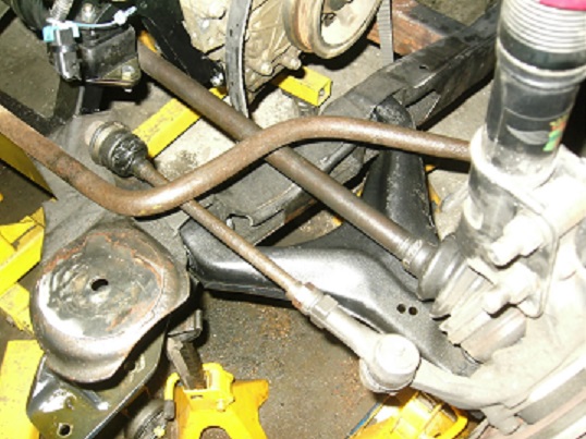
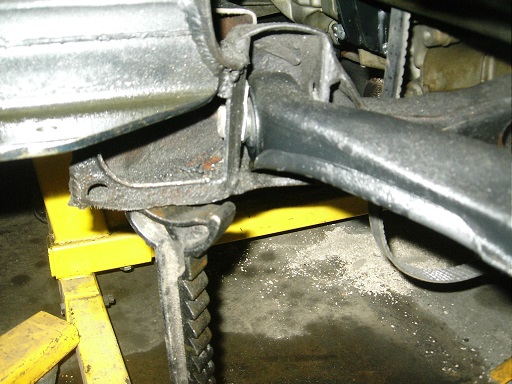
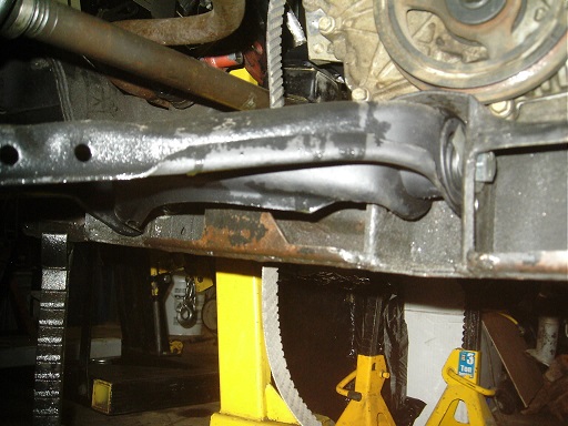
These are of the right side of the cradle. The first picture is an overall view. The second is of the rear mount with the arm pivot mounted in the lower of the two holes. The third one is the front with the front pivot of the arm mounted in the upper hole. You can also see the tilt of the lower control arm; higher at the front than the rear. That's to get some anti-squat.
If you look closely beside the bushings, you can see the alignment shims that I used to take up the clearance between the Lemforder bushings and the cradle mounts.
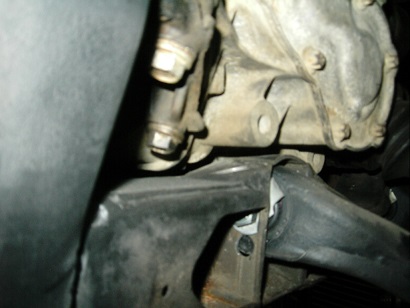
How does that work on the left side? The left forward pivot is right under the transmission. I would not have thought there would be enough room there to raise the pivot. Do you have pics?
The Indy pace cars had the rear of the cradle spaced downward--and maybe eccentric forward cradle bushings in order to raise the front of the cradle--in order to reduce/eliminate pro-squat. I like your idea of raising the cradle to improve the rear camber gain and roll center, but then the power train goes up as well. In order to keep the CG low, the engine mounts would have to be modified to lower the powertrain back to where it was... but then you have less room for raised control arm pivots AND the oil pan is hanging below the cradle and vulnerable.
Of course that raised the front end and reduced caster, so I need adjustable control arms to go along with it and a method to lower the front end back down. I have 2" lowering spindles for that, but that's not a way that's available to everyone.
I just checked the transmission-to-cradle gap on the cradle in my garage.
It's hard to get a precise measurement, since the underside of the transmission shape has an irregular shape, but the top of the cradle could definately move up an inch (or close).
Here is the setup: 4-speed Muncie with ribbed case Rodney Dickman polyurethane transmission mounts 1985 cradle
One of the reinforcing ribs on the case may have to be locally ground off, but the actual main wall of the transmission could remain intact.
Originally posted by Will: The Indy pace cars had the rear of the cradle spaced downward--and maybe eccentric forward cradle bushings in order to raise the front of the cradle--in order to reduce/eliminate pro-squat. I like your idea of raising the cradle to improve the rear camber gain and roll center, but then the power train goes up as well. In order to keep the CG low, the engine mounts would have to be modified to lower the powertrain back to where it was... but then you have less room for raised control arm pivots AND the oil pan is hanging below the cradle and vulnerable.
I consider the suspension geometry to be more important than a 1/2" difference in the C of G of the car. I placed the drivetrain according to the space available and used poly trans bushings and engine mounts to minimize movement.
To complement the raised cradle, I also moved the tops of the strut towers in an inch per side. This increases the camber gain. Camber gain from my present ride height is -0.6 and -0.5 degrees for 1 and 2 inches of compression respectively (total of -1.1) and +0.8 and +0.9 degrees for 1 and 2 inches of droop. I typically use -1.8 camber in the rear, so that brings my rears almost vertical under heavy braking, then back to proper camber when cornering. The camber change in roll moves the inner tire a little more upright than body roll takes away while maintaining camber on the outer so I'm satisfied with the geometry for now. If needed, I can move the struts in a bit more, the coilovers leave a bit of room to play.
For bumpsteer, I have 0.004" and 0.010" toe-in in compression and 0.055" and 0.150" toe-out in droop for the same aforementioned travel, essentially acting like Ackerman at the rear. I'm deciding whether to keep that or change that for zero bumpsteer but turn-in is pretty good due to the zero toe (from about 3/16" toe-in static) on corner entry that changes to toe-in/Ackerman in the corner. Once I'm done with the other suspension stuff at the front and get the car debugged again, I'll see if that is worth changing.
My oil pan is about an inch above the bottom of my new front crossmember, and I've tilted the engine back by 5 degrees to help with oil movement under hard braking. That 5 degrees is about the same as going from 1.2 gs down to 1.0 gs under braking, a nice improvement for a wet sump car. The pan is baffled well of course but every little bit counts.
[This message has been edited by mender (edited 12-04-2017).]
Originally posted by Will: The sealed ball joints are a great product for a street car, but for a race car... why didn't you just replace your spherical bearings?
I'm developing weld-in sleeves to replace the stock bushing sleeves. The weld-in sleeves accept spherical bearings and also have shaft seals on the spacers to keep crap out. When the spherical bearings eventually wear out... just knock the old ones out and install new ones.
I made the spherical bearings non-servicable because the rules said they had to be made with hand tools and a welder. Scrap tubing for the sleeve and spacers, everything welded together then installed on the control arm. I'll be cutting the old ones apart and putting a set of the new bushings in for race spares.
The Lemforder ones are pressed in and also plug-welded through the original sleeves so shouldn't move or deflect. To replace I just grind off the plug welds and press them out. I think the loads will transfer to the beefy part of the control arms where they meet the sleeves but I may reinforce the sleeves on the spares, good point on impact loads and such.
[This message has been edited by mender (edited 12-05-2017).]
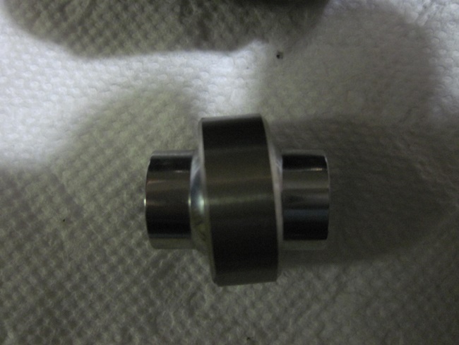
I think there is a bit of confusion as to how these bushings are constructed. They are only suspension bushings in the sense that they press in to a sleave on a control arm same as a rubber bushing does. But these are really a type of spherical bearing designed to go in to a control arm. The rubber at each end just seals the grease in making them better for street use than a rod end or bare spherical bearing as in Mender's old setup.Here is a picture of one that I put a bolt in and twisted to show the kind of deflection that these bushings are capable of -
And that is not the maximum, the rubber seals cause them to relax after twisting them as much as I can. This is a similar bearing that QA-1 sells for mounting their coilovers for people that have shocks that don't line up close enough for normal bushings-
Pretty sure if you cut open a Lemforder you would be looking at something very similar. I just finished the lower control arm front passenger side and these bushings are a dream come true as far as I am concerned. No more binding and there will be no unwanted movement of the tire caused by bushing deflection. Thanks to Mender for showing us this product.
I made the spherical bearings non-servicable because the rules said they had to be made with hand tools and a welder. Scrap tubing for the sleeve and spacers, everything welded together then installed on the control arm. I'll be cutting the old ones apart and putting a set of the new bushings in for race spares.
The Lemforder ones are pressed in and also plug-welded through the original sleeves so shouldn't move or deflect. To replace I just grind off the plug welds and press them out. I think the loads will transfer to the beefy part of the control arms where they meet the sleeves but I may reinforce the sleeves on the spares, good point on impact loads and such.
They may very well have a plastic liner. BMW ball joints for E30 and other 3 series control arms (also made by Lemforder, of course) have liners. Welding to the outer shell may have melted the liner and definitely messed up any heat treatment in the outer shell.
Yes, these have the PTFE liner as well. We use lined rod ends on the race car and they seem to survive quite nicely and no clattering.
The outer shell is carbon steel and reasonably thick so I didn't worry about welding on them. The bushing had the same stiction before and after plug welding but I only did a moderate plug weld. Welding them directly to a control arm (no sleeve) would likely cause issues with the liner. The bushings will allow 7 degrees of deflection, not a tremendous amount but enough to compensate for what I'm doing with them.
These bushings have a minimum projected street life of 60,000 kms in a Mercedes but I'll see how well they stand up on the track. At 80 hours of track time, the monoballs were worn out and had a surprising amount of slop in them. My rear sway bar was keeping things fairly snug so I couldn't easily feel the slop with the car up in the air on the hoist. I took off the sway bar and was not happy that I had missed this, hence a redo of the rear sway bar setup to go with the new control arm bushings.
For those paying attention, the sway bar shown in the picture at the top of the page is the one going in and will be connected to the struts instead of the lower control arms. It weighs 14 lbs less than the Herb Adams bar yet will have the same roll resistance. I'm also going to make it adjustable with sliding clamps on the straight section. No more control arm binding, lighter and adjustable.
[This message has been edited by mender (edited 12-06-2017).]
I guess if you do your own alignments, then it doesn't matter, but I'm wondering if it's any more trouble for the alignment shop when a car has sway bar brackets installed sandwiched in the strut-to-knuckle bolts.
What I like about the sway-bar-attached-to-the-strut setup is that the ball joint is no longer subjected to a pulling force that may pull the ball out of its socket.
Not that the sway bar on the wishbone is a terrible idea (I had that on my old Fiero)... but we've all seen double-wishbone Hondas with dislocated ball joints on the side of the road.
I saw a ball joint supporting the lower extremity of a steering column of a snowmobile. It was a plastic non-serviceable piece, captive in a piece of steel, which was then welded to the steering column.
It was explained to me that the welding operation was of short enough duration, and that the weld bead was physically far enough from the plastic parts that welding would not damage the ball joint.
So at least in the snowmobile world, welding to a ball joint can be considered acceptable. Passenger cars however, probably definately have much more strict longevity/warranty requirements.
[This message has been edited by pmbrunelle (edited 12-06-2017).]
The 84 to 87 rear suspension mounts do not run parallel to the centreline of the chassis. Would there be any advantage to make them run parallel geometry wise?
Depends on what else you wanted to do with the geometry or hardware. For example, if you wanted to convert the control arm from an A-arm to an H-arm, you'd need to rework the inner pivots or the arm will be twisted back and forth through suspension travel and eventually fail.
I would retain the A type arm but make new inner mounts that would be parallel to the chassis. The A arms would be lengthened as needed to keep the ball joint in its stock location. Then I could modify the upper arm mount so it would be parallel as well. The advantage in my set up would be longer lower control arms and it would be easier to get both sides perfectly matched. I just don't know if there are any other advantages to being parallel. And I am trying to decide if it is worth the work to do it or not.
[This message has been edited by wftb (edited 12-18-2017).]
I *think* that the plan view angle of the control arm pivots was selected in conjunction with the anti-dive angle in order to minimize the amount that the wheel moved forward as the suspension compressed. This a measure to improve ride quality. It may also be a measure to keep the caster more or less constant as the car dives under braking.
Yes, I said "dive". The 84-87 Fiero rear was designed as a front suspension before the Fiero used it. It was not geometrically adapted to be a rear suspension, which is why it has problems. Why couldn't GM have borrowed the Toronado front end for the rear of the Fiero?
If you're not concerned about any of the points above, go ahead and relocate the pivots. I plan to, and I finally had my epiphany about the most elegant way to do it.
This is copied directly from a pdf, I'm not sure how to link to a pdf. If you search this exactly, the pdf link should come up, but its just pretty generic info.
" MOOG PROBLeM SOLveR CONTROL ARM BUSHINGS "
It seems to say they are available for these makes and models, so would need to run a cross reference.
Note that those are intended to replace "vertical" bushings in control arms. There won't be an application for Fieros. They most likely won't have a small enough ID to fit in the Fiero control arms as they've been designed to replace bushings that are primarily sized to absorb shock.
[This message has been edited by Will (edited 12-21-2017).]
I put the Del-a-Lum bushings in to my RCC rear control arm. Only one side done so far. I had to narrow the bushing assembly by 1/4" to make it fit in the cradle. The arms are made out of 1" by .120" thick tube and the plate steel is about .2" thick. Total weight as shown is 6.2 lbs. I got rid of the control rod holder I no longer need.
[This message has been edited by wftb (edited 12-29-2017).]
Just wanted to post that I am now driving my car with the febest bushings in the front lowers and they are working great.Only about 300 KM so far but no problems at all. Someone asked earlier about road noise and there is no difference between these bushings and poly. They really have changed nothing road noise wise.I will report back when I have put a few thousand KM on but really looking like a great mod.
[This message has been edited by wftb (edited 03-01-2018).]
I can't say if they are still available but Herb Adams made a set of control arm bushings for the Fiero that were of the spherical design. They required welding after assembly but they came with all of the necessary items including the grease fittings and spacers. I had the complete set but they have been lost due to moving and occasionally I find pieces of them around the shop.
The Del-A-Lum bushings on the control arm above used to be made for the Fiero and I got the set that I modified to fit the tubular arms from West Coast Fiero about 8 years age. No longer produced by Global West when I looked recently and not listed on WCF anymore. Trying to find Herb/Matt Adams or VSE yielded no luck. But pics of his stuff would be nice. Supposedly some of his used parts are for sale on Ebay.
[This message has been edited by wftb (edited 03-03-2018).]
I now have about 2000 KM on my new lower bushings. I decided it was a good time to crawl underneath the car and check everything over. The bushings have been working great, no signs that anything is wearing prematurely or quirky handling going on. What I wanted to check on was my welds. Replacing all the lower bushings was the biggest mod I have ever done to the suspension arms and I did a lot of welds. Not being a welder by trade, I keep a close eye on these things. It was nice to see no evidence of cracking or any damage on any of the welds.
Check out Moog K200174 next time you're in the market for ball joints. It's has a shoulder OD of 1.517, minor OD of 1.344, length of 2.123 and is made for a 12mm bolt.