I don't remember off the top, but that OSE 12P looks fascinating... more digging for me to do now!
Today, I started on the rear suspension, got a bunch of work done on it!
When I put the engine in originally, I went ahead and put in prothane bushings. I think I didn't grease them enough, they always squeaked. So this time, I'm going to make a couple of modifications to the bushings, then add some zerk fittings where applicable.
I started with a 1' long piece of delrin 2.5" In diameter, Cut It down to size, then bored a hole in it, then sliced it into little washers with a parting tool. Then I took each bushing and cut off the flanges off of each of them. What I am left with is a hybrid, delrin/polyurethane bushing.
Then, I got busy making a ton more of these.
For the adjustable Toe link, I did something a little special. 88's have a problem when the rubber deteriorates on the toe links, or when poly is installed, the metal sleeve slides down the bushing and eventually comes in contact with the cradle, and/or the upright, and starts to saw into them. So I made a cup shaped delrin bushing that will prevent that from happening again, by ensuring that the sleeve can't slip off the poly.
Then I got really busy with the sandblaster and blasted clean the uprights and the links.
I also ordered a new pair of wheel bearings. I had an unusual, and unfortunate mishap with one of them just before I pulled the engine for this project. See here for details. https://www.fiero.nl/forum/Forum2/HTML/125790.html Needless to say, I went for a set of bearings that weren't just cheap replacements. I specified Timken's... at nearly 4x the cost of the cheapest ones I could find. No kidding, you can get a PAIR of new "513011K" rear Fiero wheel bearings to your door for $40 on eBay. Shipping included. But you have been warned...
Another task, back to the fuel lines. Since I decided to go all Nylon and Quick disconnect on my fuel lines, I ordered a few parts to make this happen Dorman parts:
I also ordered 10' of 3/8" and 5/16" nylon fuel hose too. I'll post more details when I actually do the fuel lines themselves
And, I received my Stainless scrubbers that I will be using as a coalescent inside the air/oil separator. I ordered 12, thinking I'd need 3 or so. Nope, one was plenty. These are nice because I can be reasonably assured that I will not need to worry about pieces coming off and going down into the oil pan.
Yep, one's plenty.
I'm still a bit concerned about the mounting location for this piece though. It looks like the spot that I have slated for it might be a bit more crowded then I initially thought. It's looking like it might go in the wheel well where the old air intake and water separator were. There just isn't any space left inside the engine bay. I've truly packed every possible space with every piece of needed equipment. It's insanity I tell you!
The only thing that is holding me up right now, is the clutch pressure plate. Hopefully Spec will pull through and I'll have that soon. Then, I can actually start finalizing my setup, and actually tightening down some more bolts.
Once I get this suspension done, and the clutch installed. I'll really need to focus long and hard on getting the heat shielding done. It seems like the crossover is such an inconvenience. It's near the air intake, The turbo compressor, the throttle body and it's wiring, the CTS, the intercooler and plumbing. So it seems that the solution is to really concentrate on shielding the crossover from everything really, or build heat shields for every one of these items. Either or both of these solutions must be considered.
Autospeed still expressed some concern with the possibility of some steel shards coming loose over time when they performed this catch can modification, I'm not sure what they did but I think they installed a piece of screen over the drain and vent hole to make sure it didn't happen. I've been running a standard cheap ebay catch can with the see through level hose on the side for months now, with a vent to the inlet air pipe to the turbo to help suck the vent gasses through. The inlet port from the valve cover has about a 3" tube connected internally directing the vent gasses to the bottom of the catch can to help separate oil before venting out the top. So far I have yet to see any oil register in the level tube. I run 15W50 Mobil 1 so that may be helping keep the oil mist to a minimum.
Got my wheel bearings and fuel hoses in today. The fuel hoses are 10' rolls of 5/16" and 3/8" Nylon fuel hose. I'm actually a really big fan of the plastic fuel hoses with quick disconnects. This allows for flexability, small packaging, and if protected correctly, infinite lifespan. Just all around easier to deal with. It's not all that expensive either. A novice can just go to Autozone, pick up a Dorman 800-229 and 800-230 a 3/8" and 5/16" compression fittings, put those on the tank, then make up the plastic lines that will plug into practically any swap.
Like I was saying in my last post, I sprung some extra $$$ for the Timken bearings. I could have spend $40 on a pair of brand new pieces of junk. But I still think at 4X the price, they really aren't even all that expensive. Old Duralast bearing on the left, new Timken on the right. You can see right away that the wheel flange is WAY thicker. Good. I don't ever want that to fall apart on me again. Also, it looks like the outer bearing area between the wheel flange and mounting flange is also MUCH heavier. Perhaps a larger bearing lives in there then normal???
I can say though, that the crappy Duralast bearing looked exactly the same as the OEM bearings. Physically indistinguishable from OEM. But you can see that with the Timken, they at least made an effort at improving the bearing, even though they are competing against some slash-throat pricing.
I am still waiting on a pressure plate. Hope it comes in soon! It's really stalling this whole project, and worse, my motivation.
In the meantime, I've been painting the cleaned suspension parts and getting a few more supplies together. I need very little more then the pressure plate to finish this whole project. I still need to make a pair of mount brackets for the FMHE, and start running some lines front to back.
Today, I started on the rear suspension, got a bunch of work done on it!
When I put the engine in originally, I went ahead and put in prothane bushings. I think I didn't grease them enough, they always squeaked. So this time, I'm going to make a couple of modifications to the bushings, then add some zerk fittings where applicable.
I started with a 1' long piece of delrin 2.5" In diameter, Cut It down to size, then bored a hole in it, then sliced it into little washers with a parting tool. Then I took each bushing and cut off the flanges off of each of them. What I am left with is a hybrid, delrin/polyurethane bushing. https://images.fiero.nl/2012/IMG_1958.JPG
For the adjustable Toe link, I did something a little special. 88's have a problem when the rubber deteriorates on the toe links, or when poly is installed, the metal sleeve slides down the bushing and eventually comes in contact with the cradle, and/or the upright, and starts to saw into them. So I made a cup shaped delrin bushing that will prevent that from happening again, by ensuring that the sleeve can't slip off the poly. https://images.fiero.nl/2012/IMG_1960.JPG
Where did you get the delrin? That is such a good idea, I want my suspension to be able to move easier!
Just go to rod ends in the lateral links. Urethane is for suckas and has all the problems you noted and then some. Stop wasting time trying to fix something that should be trashed and go with what GM should have put in those links in the first place. http://realfierotech.com/ph...p?f=3&t=2573&start=0
There are a few threads on it on this forum as well. I think FieroGuru has found rod ends with integral sleeves that help significantly.
Thanks Will. I'm seriously looking into that now. Just so long as they are durable, and greasable, I'm totally cool with using them. I will be driving this car a buttload once It's up and running. So the links have to be very durable, if not lifetime parts. I honestly hate poly, I have to fix a serious issue in the front end where the poly siezed to both the inner and outer sleeves, and worked the sleeve out of the control arm. it's a crap sandwich up there. There is no way I would ever put poly back in unless I can reliably grease it externally. That was my current intention. But... A good and durable heim setup I'd be all over. Bushing compliance be damned! So, it looks like I'll be doing a little research and perhaps some shopping.
QA1 PCYM Series rod ends feature a 2-piece chromoly steel design and a heat-treated, black oxide coated body for corrosion resistance. The ball is heat-treated as well with a precision-ground, hard chrome plated finish. The ball is specially designed for high misalignment applications. QA1 PCM Series rod ends are built to last.
I would not suggest greasing them. All it does is give something for the dirt/grit to stick to and wear them out faster. I am up to about 3K miles on my setup with lots of driving in the rain and they are still tight.
I did bore out some large nuts and tacked them to the tubes so I had a good method to tighten them.
[This message has been edited by fieroguru (edited 07-12-2013).]
Thanks Will. I'm seriously looking into that now. Just so long as they are durable, and greasable, I'm totally cool with using them. I will be driving this car a buttload once It's up and running. So the links have to be very durable, if not lifetime parts. I honestly hate poly, I have to fix a serious issue in the front end where the poly siezed to both the inner and outer sleeves, and worked the sleeve out of the control arm. it's a crap sandwich up there. There is no way I would ever put poly back in unless I can reliably grease it externally. That was my current intention. But... A good and durable heim setup I'd be all over. Bushing compliance be damned! So, it looks like I'll be doing a little research and perhaps some shopping.
I know it's counter-intuitive, but greasable rod-ends are contra-indicated.
Just get high quality (minimum $25 each) steel on steel and seal them with sealing washers and rod-end boots.
My thinking is that we are dealing with is something similar to a tie rod end. They grease and seal those, and they have lube grooves in them to promote grease flow. That's what OEM uses, and it lasts a really long time, but usually winds up needing to be changed out once in a cars life. So I'm a bit weary of metal on metal with no lube. What I think I'll do, unless I am convinced through more research otherwise, is get a higher end grease-able setup; Grease it and run it. If it all goes tits up, I'll get new joints and run them dry. Not like its difficult to replace joints anyway, but it is a pricey experiment in durability. I'm doing some serious research in the meantime. Overall, I like the idea though. They are pretty, and they should make up for some of the shortcomings of the Fiero's old design. It's also got me thinking about making my own custom press-in Front A-arm Joints, since the poly up there has been quite troublesome. And, I have the resources to make it happen. I'll let you guys know what I wind up deciding to do.
Originally posted by Fierobsessed: Overall, I like the idea though. They are pretty, and they should make up for some of the shortcomings of the Fiero's old design. It's also got me thinking about making my own custom press-in Front A-arm Joints, since the poly up there has been quite troublesome.
I'm designing weld-in spherical bearing sleeve that will work on '84-'87 rear arms and '84-'88 front arms. I'll be glad to share the design with you.
It's been a little while, it's time for an update!
I've been in a bit of a holding pattern for a while mainly due to the clutch. But finally I have a moderate clamp force pressure plate. However story doesn't end there... I ordered a medium pressure 2,400 Lb 9-1/8" pressure plate from Spec. This is a 50% increase in applying pressure.
Immediately I got right down to inspecting my purchase. I have to give Spec their due credit. This is one pretty pressure plate. Manufacturing defects? Zero. But what is it? What did they do to increase the applying force? I noticed that it seemed like the pressure plates surface is awfully low in relation to the mounting surface. So I broke out the caliper and a straight edge to take a measurement.
So, .271"
Ok so... The next obvious thing to do was to measure my Clutch Net disc.
That means that...
Oh, that's not so good.
I sent an e-mail to Spec inquiring about the intended clutch thickness for this model pressure plate, their answer was .350" to .360". Which is really helpful. Or in my case, bad news. Although I could just install it, and I could drive with it, It would have a minimal life, and will never have full holding capacity.
I happened to have a pressure plate from when I originally put the 3.4 DOHC in my car already, it is a Valeo brand stock replacement. Turns out it is exactly the same donor pressure plate. This gave me a unique opportunity if you know what I mean...
Ok here's the difference They drill out the three rivets on the straps that secure the friction surface, and they re-machine the fulcrum point inward, which does cause the friction surface to lose some clamping distance, which can be made up for with a slightly thicker clutch disc. Intern, there is a dramatic increase in holding pressure. With that bit of machining done, they put the friction surface back, replacing the rivets with new ones. It would work great but only if I have the correct thickness disc for their pressure plate.
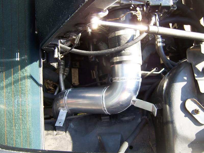
I have some thinking to do. This problem is not yet resolved. But in the meantime I've been very busy. I loaded the engine back in the car for another fit check. And it was nearly perfect. Only the dipstick tube needs an adjustment. The air filter the silicone elbow and stainless joint all fit, and it looks like the oil separator has it's home too.
I'm back on hold on this project. Getting married! So needless to say the next week or so I'll be a bit preoccupied!
I've mentioned it before but, given how many times I've read about problems with the Spec combos on first go around, you may want to visit your local clutch builder if you have one. My pressure plate started out as a stock HD unit that was modified the same day to 2300 lbs clamping pressure. At this point given how well it has held I wouldn't consider buying a plate, or disc from any company unless the local builder couldn't supply it.
Nah, it's just too much work, and not financially viable. I'll save the details of why for the conclusion post I will do once this project is more or less done.
Onward!
I am pleased to say, that now that I am married, that I still have my Fiero's and I'm still working on this project. Well, at least just getting back into the groove now.
So I finally decided to grab the bull by the horns and make a custom higher strength pressure plate. This was a really fun project, and one I only wish I knew then, what I know now, so let me share.
The fun starts with a standard aftermarket Getrag pressure plate. This one is a Valeo PN AMC44, Sold under the brand name Dynapak.
First things first, drill the rivets from the pressure plate face side, I started with a 5/32" drill, then only drilled a little bit down with a 7/16"
Once the rivet head was just starting to show break through, I removed the remains with a pair of pliers, the idea is to not damage the strap in any way, so drilling had to be done very carefully.
Head removed
I very carefully pried the straps off of the rivets with a flat head screw driver, they popped off rather easily.
Oh, I almost forgot, label! Is orientation important? I don't know, but It can't hurt. And I know my 1 is backwards, I wrote it while it was upside down and I suck at it.
I tapped one of the straps out of the way so I could remove the pressure plate.
With that one strap out of the way, it wasn't difficult at all to free the pressure plate
Remove some rivet remains
Now for the fun stuff, and another reason I love my 12" lathe
All I have to do is move the pivot point closer to the fulcrum, So it started out like this:
And after a little reworking, it's now like this:
Measuring from the face to the pivot point, it was .770" stock
I cut it down at the same outer face angle to .720" This pressure plate lost some throw, but gained some leverage.
For assembly I needed to make some rivets. No problem. Another easy task for the lathe.
I put the plate back in place and tapped the one moved strap back into place and slipped the rivets into place
Today's custom tool... A rivet thingamabob. Some 1/4" steel hastily welded to a vice grip. But oh, what a wonderful tool it is.
And what does this tool do? It clamps the rivet into place for pressing, without interfering with the pressing process.
I also made up a small shaft of steel to do my rivet pressing, then mounted it all up and pressed away.
Final result:
IT'S DONE! I finally have my clutch all sorted out. I've been on this problem since February, and I spent all kinds of money on pressure plates that didn't work out. Reworking a stock plate was more fun then I thought it would be. I'm just so relieved that it's done. Now I can start to really wrap things up and get this car going in the near future.
I've also settled on the rear suspension links for the toe and trailing links. They're on order. I'm getting excited about this project again, and that's just what I need right now.
Nice work on the pressure plate. It's cool how black box items can become so simple and easy to modify if you just take the time to measure and investigate.
Todays task was to build some brackets to mount the intercooler. These brackets slip in between where the 88's front suspension anchors to the frame, and the frame itself.
After painting and mounting them, you can see it hovering right in front of the condenser
Then it was just a matter of slipping the intercooler in and bolting it up!
And here's its final resting place. Just enough clearance to make me happy!
I still have to make up a radiator cap setup from what I cut off of the intercooler so I can fill it, I'll "T" the overflow line in with the coolant system's overflow. It's just convenient that way.
I also received some parts for my rear suspension links. I sort of ordered the wrong ones, paid a little extra for a feature I had to remove...
No big deal to remove the studs,
The rod ends I got are from QA1, they are Chromalloy Steel on Steel, 3 piece, and equipped with a zerk fitting. They really are the best thing I could find for the application. Along with those, I also got aluminum hex style adjusters, 9" and 10", and I got seals for the rod ends. I'm hoping my choice in a moderately high end grease able rod end will result in excellent performance and lifespan. We'll see. I still have to make up some spacers, but it looks like if I drill out 1/2" nuts, they will fit perfectly.
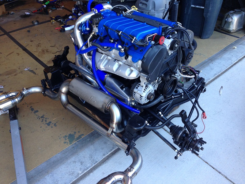
And on another side note, I picked up a new toy. I absolutely love this truck. I've wanted one for years, and now I finally have one! So hopefully before the end of the year, I will be driving two vehicles with 400 or more horsepower I'm just glad I don't have to work at it with the Trailblazer SS.
Did a bit more work on the front mount heat exchanger today. Originally, the FMHE had a radiator cap on the top on one end. But, there is no way that the intercooler would have fit between the frame rails with that overhanging the end tank.
So... I used my trusty sawsall to cut it off.
Still needing a fill port, I decided to make the coolant fill a remote mount. I welded in a 1/2" NPT bung.
I put a 1/2" 90 degree barb fitting into it. This way I can JUST sneak a hose between the frame rail and the condenser, then up to the remote fill.
The next big task, was to make the remote fill. I figured why not use the part I cut off the intercooler, and some aluminum stock to make the filler.
Ready to be mounted
Here seems like a good spot.
I still have to mount the pump, and run some lines, but the hard stuff with the FMHE is done. That's all for now!
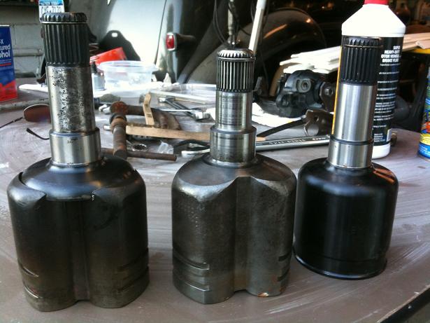
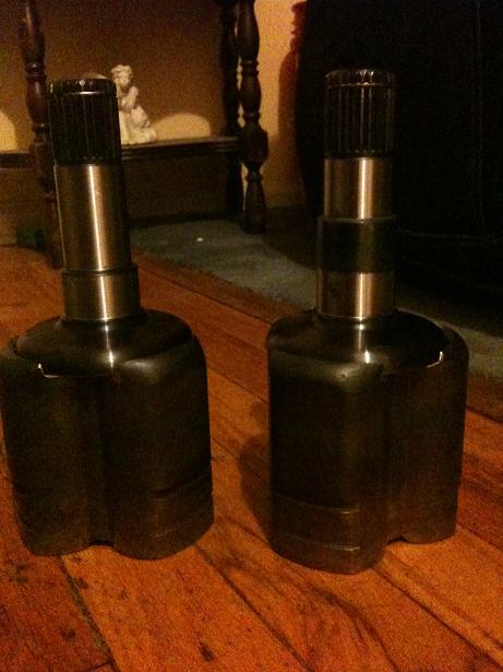
Just a little more for today, I got the itch to test out my suspension links, and the custom axle cups. Mainly to verify the depth of the tripod assembly. I built my axle cups a long time ago but here they are as I was making them
So it is an EMPI aftermarket axle for a Chevy Equinox that was the donor for the stub shaft, and I machined a stock manual Fiero cup to press onto it, then welded it in place. On the one, I had to add a sleeve to extend the sealing surface to mate with the seal.
That was 4 years ago.
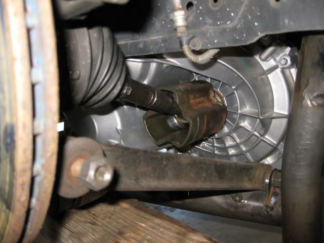
Today I wanted to test fitment. My drivers side axle shaft is from a 90 something, probably 93, Corsica with a 4T60. I knew it would have a beefy short axle shaft. the outer CV is the original to the Fiero. The passenger side has the same treatment, but it just uses a stock manual Fiero axle shaft and outer CV, with the custom axle cup. The passenger side cup didn't need to be tested, because it's in the stock location almost perfectly, but I needed to test the drivers side because the axle line has shifted forward for the G6 transmission. It's substantially closer to the crank itself then it was on the Getrag, and the axle cup is further out on the drivers side as well, and the angularity on a shorter axle can spell disaster if it is not considered.
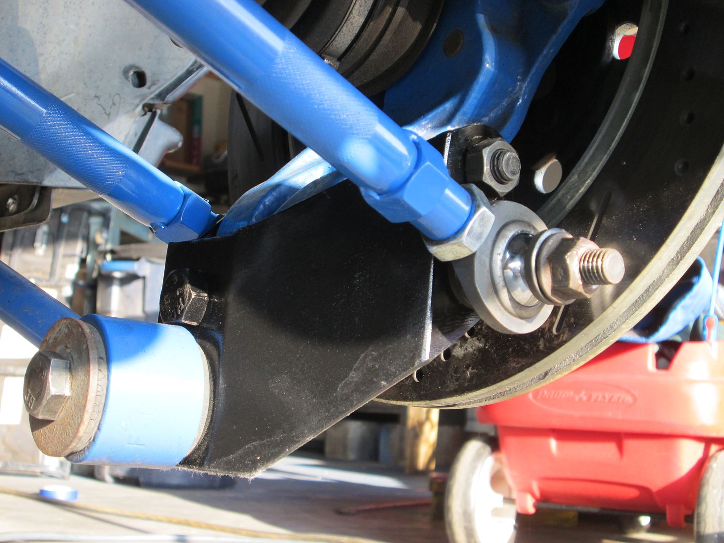
The links look good! I did wind up drilling out 1/2" nuts to turn them into spacers. They fit absolutely perfect!
All the zerk fittings are pointing downwards except for the rear inboard, they can all be greased easily. Also, there are seals on either side of each rod end. the seals will allow pressurized grease to escape, but should prevent any dirt from getting in. I hope this combination will provide exceptional life span on these rod eyes!
And for the axle test, All the way up to the bump stop.
About mid-travel.
Free hanging was fine as well.
So now I know I don't have to worry about the axles. That's another check mark on my to-do list.
[This message has been edited by Fierobsessed (edited 08-26-2013).]
Today I wanted to test fitment. My drivers side axle shaft is from a 90 something, probably 93, Corsica with a 4T60. I knew it would have a beefy short axle shaft. the outer CV is the original to the Fiero. The passenger side has the same treatment, but it just uses a stock manual Fiero axle shaft and outer CV, with the custom axle cup. The passenger side cup didn't need to be tested, because it's in the stock location almost perfectly, but I needed to test the drivers side because the axle line has shifted forward for the G6 transmission. It's substantially closer to the crank itself then it was on the Getrag, and the axle cup is further out on the drivers side as well, and the angularity on a shorter axle can spell disaster if it is not considered.
And for the axle test, All the way up to the bump stop.
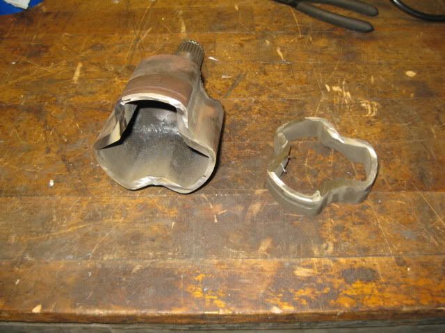
Did you spin the tripod while it was full compression? I went the same route with the hybrid tripod/corsica axle and at full compression the axle hit the inner surface of the tripod housing. However, I had the upper strut hat flipped and the tubular cradle had the drivetrain lowered 1", but then I rotated the transmission back up, so my setup was slightly different than yours. I ended up cutting the tripod housing back so there was 1 groove for the boot vs. two to gain the needed clearance.
Guru, looking at your pictures made me want to recheck. I feel better now that I did. My axle still clears the cup, but it turns out that when I tested it the first time, I did NOT hit the bump stop like I thought I had. But this time I had the whole car sitting on that one spring. I think I got it this time. It looked much closer to your picture.
My next task while the engine is still in the car was to make yet another bracket (I've long since lost track of how many brackets I've made) to hold the Air/Oil separator that I built. I was running out of space in the engine bay, but I could just squeak this in where the old air cleaner used to be. That got me thinking... What if I made a bracket that mounted exactly like the air cleaner assembly?
That was the answer!
So I bent up some metal I had laying around and found building the mount was pretty easy.
Next, I made a clamp like bracket that would hold the can, and welded that on.
A couple of bolts, and it all comes together pretty nicely!
And it slips right in, and the old air cleaner bolts hold it all in place.
It's been a very productive day again.
I am ready to pull the engine out for the very last time so I can put the clutch in, and do a bunch of finalizing so that I can put this project on the road. It's getting exciting!
Guru, looking at your pictures made me want to recheck. I feel better now that I did. My axle still clears the cup, but it turns out that when I tested it the first time, I did NOT hit the bump stop like I thought I had. But this time I had the whole car sitting on that one spring. I think I got it this time.
I normally do the axle check w/o a spring on the strut, so its easy to cycle the suspension from full compression to full droop while spinning the tripod assy.
GM went to the trouble of welding all those little top hats to the body metal in order to hold things in the engine bay... Why shouldn't we take full advantage of them?
It's been a long time since I've had any updates. Life is busy! But I'm back at it again.
After a little axle testing, and building that bracket, It was once again time to remove the engine. This should be the last time it comes out! I promise!
It's time to install the flywheel and clutch. As per instruction, I put Loctite on the bolt threads, and a grease just under the bolt heads to aid in getting the correct bolt torque. Done. Note, that I decided to use grade 8 studs in place of bolts to hold the pressure plate. I was finding that the cast iron threads in the flywheel tend to gall. There is only one solution to keeping that problem at bay. They were loctited in, as well.
Next I had to bolt up the pressure plate and center the disc. And that is done! hopefully this is the last time I will need to see the clutch for a long time.
With the clutch being bolted in, I slipped the engine back into place and mated it up with the transmission. It all went very smoothly. Then I decided to build the axles. But since these axles have 240K on them, I figured it would be a good idea to disassemble and thoroughly check them over. I'm glad I did, because I found some damage to the outer star on one axle. No worries, I had a donor axle to pull another star from.
I cleaned, greased and assembled the axles, new boots, new clamps.
And, installed! I also painted everything before assembly, It's nice to see it done. You can see that the F40 actually has its axle holes closer to the crankshaft then the Getrag. The 3 shaft design pulled the differential closer. So this axle will always be a little out of alignment, and will probably not last quite as long as it should. But that's just how it has to be.
I had one more little welding task on the crossover. I needed to add a 8AN stainless fitting to the crossover to connect the EGR to. No problem. Drill a 3/4" hole, and weld away!
Installed.
When I purchased this 12" Gas line, It was painted yellow. I stripped the paint off using paint stripper. I accidently destroyed one when I attempted to use the wire wheel and sand blaster on it. Apparently, it was a little too powerful and I poked through. But the paint stripper did a perfect job.
Hoping to cut down on unnecessary heat in the engine bay, I began wrapping the exhaust with the Lava rock header wrap. This should keep me from cooking the wiring and the compressor housing on the turbo, since the pipes pass kind of close to the compressor. It would suck to heat that up too much.
So I'm back on track and will be working on it almost daily. Soon I hope... Soon!
[This message has been edited by Fierobsessed (edited 09-19-2013).]
Everything looks good! The header wrap is nice too, just a shame it covers up those nice welds. I love the look SS gets when the welds change the color.
If you run out of places to bolt things to in the engine bay, I bought a bag of these along with some ss flange locking nuts from McMaster. ("These" is referring to the right angle weld studs)
I tore out all those right angle brackets and welded in studs anywhere I needed them. I used cushion clamps to hold the miscellaneous wires and tubes and fuel lines. They are easy to remove and it cleans up the engine bay a lot.
It took me a few hours to remove all the brackets and decide where I needed studs and weld them in place. It's a good day project.
Originally posted by Fierobsessed: Note, that I decided to use grade 8 studs in place of bolts to hold the pressure plate. I was finding that the cast iron threads in the flywheel tend to gall. There is only one solution to keeping that problem at bay. They were loctited in, as well.
That's odd. I've never heard of cast iron being prone to galling... exactly the opposite, in fact. In my experience it's very resistant to galling.
quote
Originally posted by Fierobsessed:
I cleaned, greased and assembled the axles, new boots, new clamps.
What's your axle setup? (You don't have to go over it again... just linking the post where you talked about it would be fine...)
quote
Originally posted by Fierobsessed:
So this axle will always be a little out of alignment, and will probably not last quite as long as it should. But that's just how it has to be.
I was having a ton of issues with galling on the flywheel. This is something I have not encountered in the past. Testing my various clutch combinations required me to mount the pressure plate multiple times. Each time I dissassembled it, the theads were clearly damaged on the bolt. (10.9 grade) So I used the tap a couple of times to fix the threads. It didn't really matter because the 6 pressure plate bolts on this flywheel were not located correctly on the flywheel in the first place. So I drilled and tapped 6 new bolt holes centered around the flywheels true center and installed studs. The donor flywheel was shockingly poorly machined from the factory. It's all good now I hope!
For the turbo header heat...I did the wrap thing and it did work ok, but I still had some heat issues. I went to a .020 sheet metal heat shield and the issues are gone. It's not as flashy as header wrap but it works better, especially long term.
Thought I'd mention this for anyone with these common turbo issues.
Originally posted by Slowbuild: I went to a .020 sheet metal heat shield and the issues are gone. Chay
I couldn't agree more... especially since that is exactly what I wound up doing anyway! I took the stock "Front" heat shield that I had mounted on the rear manifold (which is actually a flipped front manifold) and welded on some very thin, probably just that, .020" or so sheet metal to the heat shield. The stuff was so easy to bend using a piece of exhaust pipe as a guide, and tin snips for cutting. The welder had to be put on its lowest setting and it was still burning through easily. So it isn't by any means my prettiest weld, but It's fine enough.
I applied some heat reflective tape to the inside of the heat shield, and laid some header wrap over the top of that to keep the shield cool. It should be far cooler now.
So I went from this, which was going to cause serious issues:
To this, where I feel like there is nothing to worry about:
I also decided to build a little shield housing for my CTS. The wiring and the sensor were pretty close to the crossover, and that just didn't seem like a good thing. I'll wrap the wire with heat tape. I'll probably build another small heat shield for the crossover in this area too.
While I was at it, I added another section to the end of my water outlet pipe. It now drops off near the under car coolant line.
I had an idea. I decided to make a new oil drain fitting out of various pieces of steel gas pipe fittings. I wanted one 1/2" NPT inlet, and two 1/2" AN outlets, one vertical, one horizontal. This is a really novel idea I think. The vertical outlet will drain directly into the oil pan, and the horizontal is going to the bottom of my air oil separator. This way, any gases from the turbo aren't forced into the drain line, they can travel up to the bottom of the air oil separator, and any oil that accumulates in the separator can gravity drain down the same line into the oil drain that goes straight into the pan. This will alleviate any pressure that may build in the drain line to the separator, and allow just oil to run its way into the oil pan.
And finally, I plumbed in the oil feed for the turbo as well. So now all my oil issues are addressed. Done.
I'm going to work on the wiring a little more now. I decided to change the way I wired the fuel pump. I'm not particularly thrilled with the factory layout. Get this:The power goes from the fusable link near the battery through the body harness to the fuse panel in the front. Then back through the body harness to the C203, to the engine harness. Then to the relay and oil pressure sensor for control, then back through the engine harness to the C203 Then to the body harness for a third time, then back into the engine bay where it finally goes to the fuel pump connection. It's all a bit much.
This circuit will now be drawing around 11-13 amps now, so I think I'll cut it down to a fuse mounted near the relay running directly to power, then leave the last bit in so I don't have to have two connectors running to the fuel pump. It'll cut the wire length into a third of what it was. Then I could re-utilize the old fuel pump power wire for something else that needs full time power. Not sure what that might be yet. Probably nothing.
After I get the wiring harness touched up, I just have some 1/4" and 3/8" tubing to make up for a couple items, then I can mount the upper intake. It's all just some detail work and the intercooler plumbing left. Then it's install...
It's been a very busy past few days. I've made a ton of progress and the engine/cradle assembly is complete. I'm just cleaning the garage, which got way to messy during the final assembly phase, then I need to prep the car to receive the package, including installing the intercooler lines and pump as well as some other engine bay preparations.
Some recap on what I've done most recently, I...
Redid the little bit of fuel pump wiring I had mentioned in the previous post, and added a fuse to the circuit which will go by the relay. Tidied up the wiring, added some heat reflective fiberglass tape Finalized the wiring harness in general Removed the original 3/8" valve cover breather port stubs and installed 1/8" NPT plugs as they were no longer needed at all. Cleaned the belt covers and the top cover, painted the hardware and installed Installed the sway bar Tightened up all connections Modified my PCV pipe that also operates the blow off valve Installed the turbo blanket Installed the various water lines to the turbo and wastegate Added the connection hoses to the engine for the coolant and breathers.
I worked on some of the smaller lines, like the fuel pressure regulator reference line, since this is now a boosted engine, I felt it was appropriate to place some insurance on all the vacuum lines. I used aircraft style fastener wire and pliers to wrap and tighten most of the smaller lines. I could have used small zip ties instead, but I'm pretty good with the stainless wire and I don't trust cheap zip ties. The connections were very secure after this.
An decision had to be made. Which wastegate spring should I use?...
After much debate, since the spring will be nearly impossible to get to in order to change it, I settled on the spring on the far left, it's natural opening pressure is 7.25 PSI. I originally had installed the smaller spring above it, which was 4.35 PSI. It really bothered me how easy it was to open the wastegate with just my fingers, let alone the buildup of exhaust pressure. 15 PSI of exhaust pressure would likely have pushed the valve open against that spring. It just seemed too weak for me to be comfortable using it. I may not know what kind of pressure will be in the exhaust manifold, but I wasn't going to let that inhibit boost or spool.
The other reason the spring selection was touchy is because I chose to use an ECM controlled boost solenoid, so the ECM can regulate boost at whatever PSI I want. So I wanted a weaker spring, as the computer's ability is only to increase boost past the spring setting by delaying the application of control pressure to the wastegate. So if I put in a bigger spring, I lose some flexibility in how much range the ECM can control boost. So I figured I wouldn't want to have anything less then 7 PSI as a setting.
However, one more thing I will do is apply a strong vacuum to the other port on the wastegate to pull the diaphragm open so it will not boost during initial tuning. 7 PSI might be a bit much for rough tuning. A vacuum line with a check valve should do the trick.
Another thing I had to do was add some Fiero style exhaust hangers to the front of the exhaust.
I also made and added some cradle intercooler lines.
Once all this was done, I can say the engine is ready for the car. But the car isn't ready just yet.
One last walk around.
I also drained the gas tank. I used the fuel pump to empty it most of the way. Once the fuel pump chugged its very first bit of air I immediately cut it off and drained the tank by manual methods. I learned that the Fiero's fuel tank actually has about a gallon and a half, or so of fuel when the pump finally quits on flat ground This is what I got out of it after the pump was finished.
I'm going to finish organizing and cleaning the garage, then I will get the tank ready, and load it in, do the new intercooler lines to the front, find the intercooler pump a home and wire it in. Then its just some cleaning and painting in the engine bay and the engine will go in. Hopefully within the next day or two.
I had a really busy week. I've been working on the car as much as I can stand to. I didn't take a heck of a lot of pictures, but heres the jist of it.
The engines in. It runs. It boosts. It drives.
Without tuning it much it's not really drivable. It idles ok but I'm having serious issues with data logging. so I'm having trouble with diagnostics right now.
After getting it up to temperature it sprung a water leak that required me to drain the coolant and remove the turbo. Which I might add, is a huge pain in the butt
I found later on that the leak was actually not my welded pipes, but rather the banjo bolt itself which was damaged in manufacture
Nothing a few seconds on the lathe couldn't fix
I got it all back together now. And am struggling to maintain a connection from the ECM to my computer.
I did have an issue where somehow, inexplicably 12V was making it to the map sensor wire, causing the car to fry a computer and make the car not run. If the MAP readings weren't pegged, it might have been a bit more difficult to find. But the real question is, how does 12V get into a direct wire from the map sensor to the ECM?!? Either way, I will have to fix that!
In the meantime I've bypassed that wire externally for the time being, and am having quite a time trying to get the ECM to communicate. There is something weird going on that I will get to the bottom of.
That's the same thought I was having. But there is only a 30mv difference between the chassis and the ECM when the engine is running, that is well within acceptable. If it were a volt or more I could see some serious issues. If anything, that tells me that my engine is well grounded.
I figured out what was the issue with the MAP sensor wire and had a good laugh at myself. I intend to put in the electronic boost gage/tach, I knew I had to commandeer a wire to the dash board, and I decided to use the no longer needed "Temp warning" lamp circuit to feed the signal to the gage pod. My stupid face forgot that I wired that! The bulb was still in the socket in the instrument cluster, and it was back feeding its 12V feed into the map sensor wire. I popped the bulb out, and all is good now. I've always been a good harness builder, I even put in features I forget about.
Troubleshooting is continuing on the logging... I can't even begin tuning without data logging.
Yay! I fixed the data logging! Again, my fault, I wired in a feature I forgot about. I wanted a calibration wire to the wideband controller, I put it on the ALDL, but I put it in slot E which happen to be one of the serial data ports that IS wired to my logger. So the wideband controller was interfering with the serial communication. I moved it to an empty port and it now logs perfectly. So I took a lap around the block and logged it, now I can start dialing in! I needed to hear some spoooooling followed by some Spwishing to keep me motivated.
Originally posted by Fierobsessed: I figured out what was the issue with the MAP sensor wire and had a good laugh at myself. I intend to put in the electronic boost gage/tach, I knew I had to commandeer a wire to the dash board, and I decided to use the no longer needed "Temp warning" lamp circuit to feed the signal to the gage pod. My stupid face forgot that I wired that! The bulb was still in the socket in the instrument cluster, and it was back feeding its 12V feed into the map sensor wire. I popped the bulb out, and all is good now.
It's wired normally, 5V, GND, and Signal. But, the signal wire splits, one going to the ECM, the other runs into the C500 (D3) which was the temperature light. From there it makes it to the cluster, where it will be locally wired to the sunbird boost/tach. The key is to not have the temp indicator bulb in place. Or move the wire to a different conductor on the cluster. I forgot to do that. so the bulb was back feeding the map sensor and the ECM. Oops.


 Topic Closed


 I'm just glad I don't have to work at it with the Trailblazer SS.