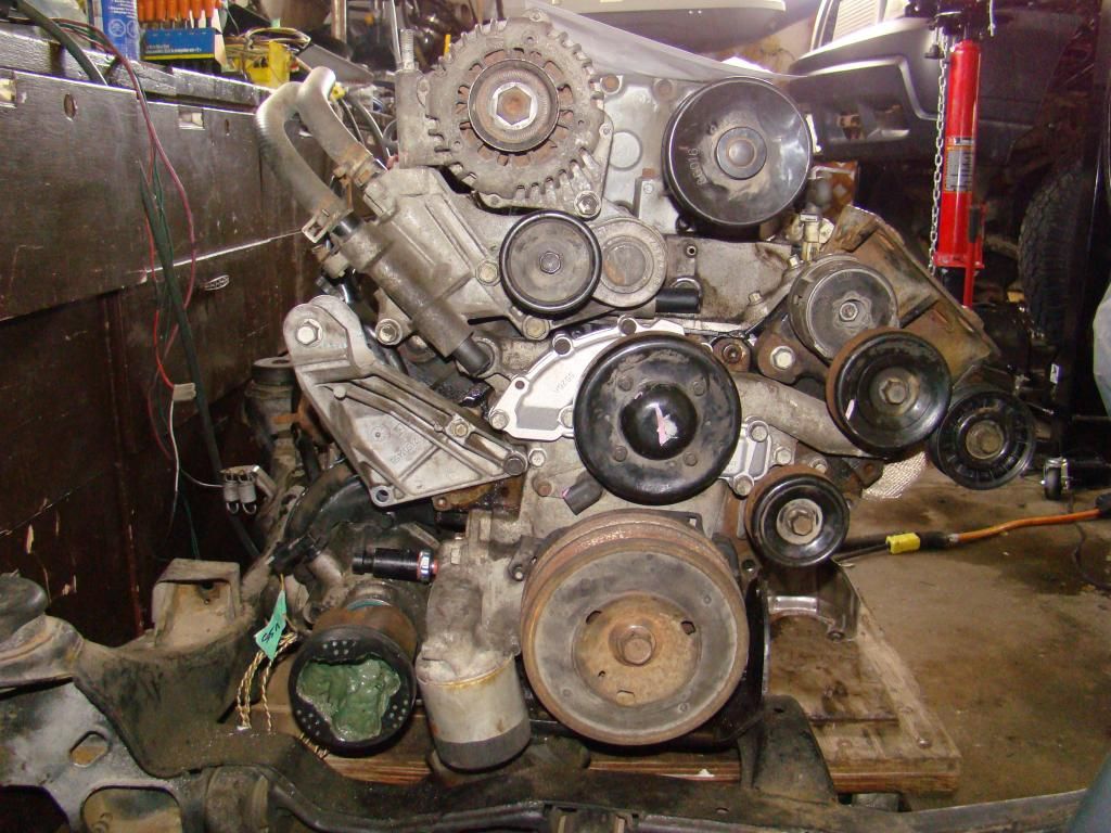
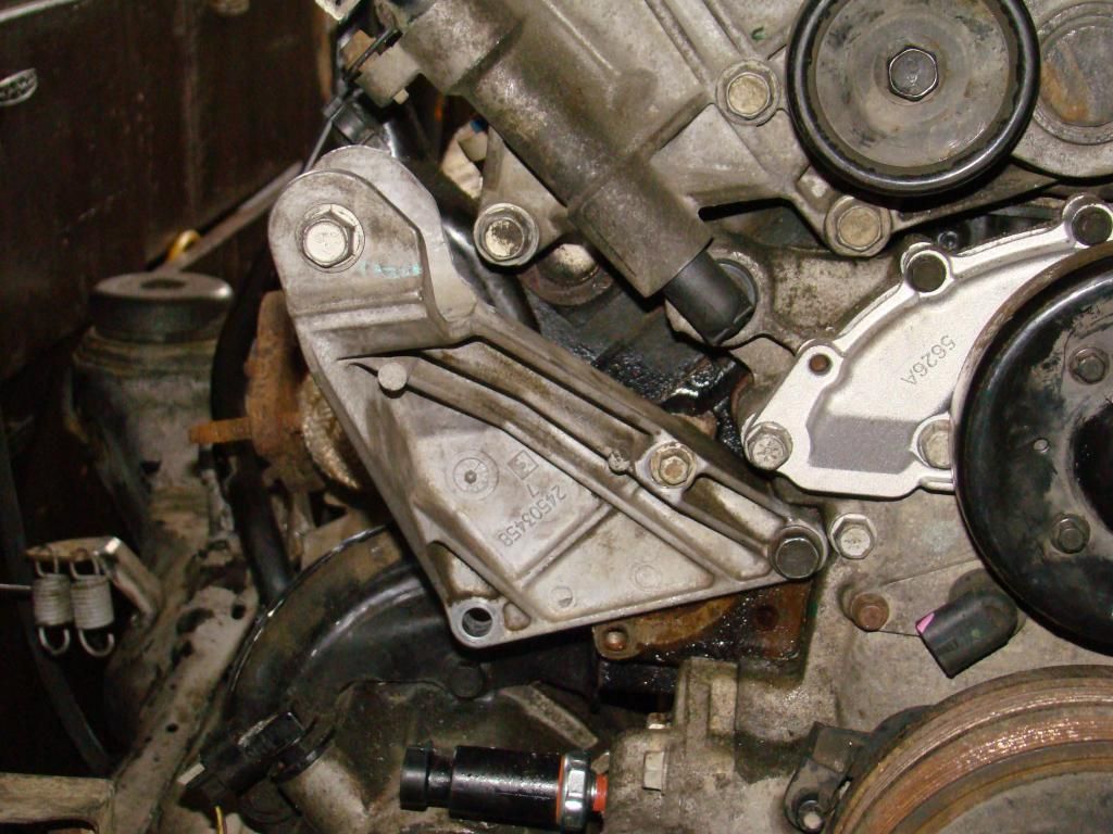
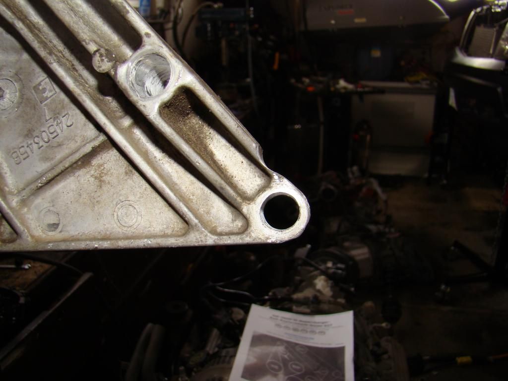
When I pulled off the alternator bracket with what ever else underneath, there are two 90 degree plastic coolant tubes. What are they called? The local napa doesn't have a clue and one broke.
They break all the time. Usually you can go into any competent parts store and say you need the two new 90 degree elbows and they will show you to them.
Here they are in metal (recommended). Almost every store carries the Doorman brand.
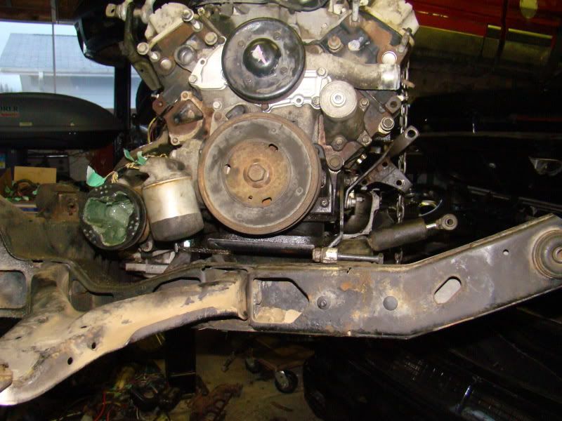
Got the metal ones ordered but they will be 4-6 weeks away. Got the engine cradle out tonight, man that was heavy. I thought it would move with the wheels but nope I had to drag that ***** by myself. Got er dun though.
------------------ 86 GT Convertable 3800
[This message has been edited by Tweeder (edited 09-06-2012).]
Hey Tweeder Congrats on the swap, I think I'm late to the conversation, but I have to put a word in for phonedawgs. I had him make me a complete harness for the 3800 NA swap I'm doing, it is totally plug-in-play, the best quality, I'd highly recommend him and his product. Anyway goodluck with the swap.
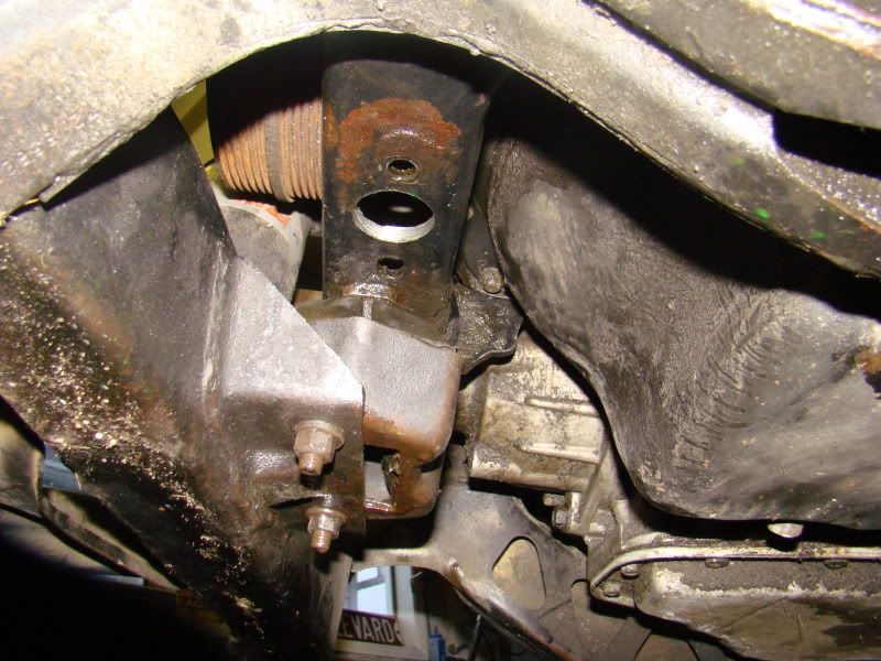
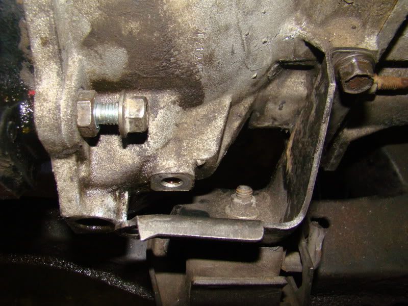
Woohoo most of the mounts from the previous swap fit. The right side and the left back fit. I have to refabricate the right rear one. Will three lower mounts work? And will I need to add a dog bone? Will post pics tomorrow.
front left need spacer for one hole on front left same as above, different angle.
front right I still have to fabricate the mounts for the strut but thats easy.
With the th125c I had another mount on the back left but that don't fit, I might be able to make it work. If not will the three mounts be enough or will I still need the dogbone up top?
I was out there working on a way to mount the shock and what not. I was on the back left corner and I could move the cradle up and down a couple inches, so I definitely need something there unless the dogbone up top will suffice. The old mount that was there from the th125c wont fit in the inner cradle and mount up. what do y'all do to secure that corner?
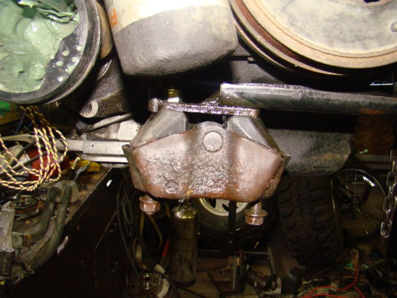
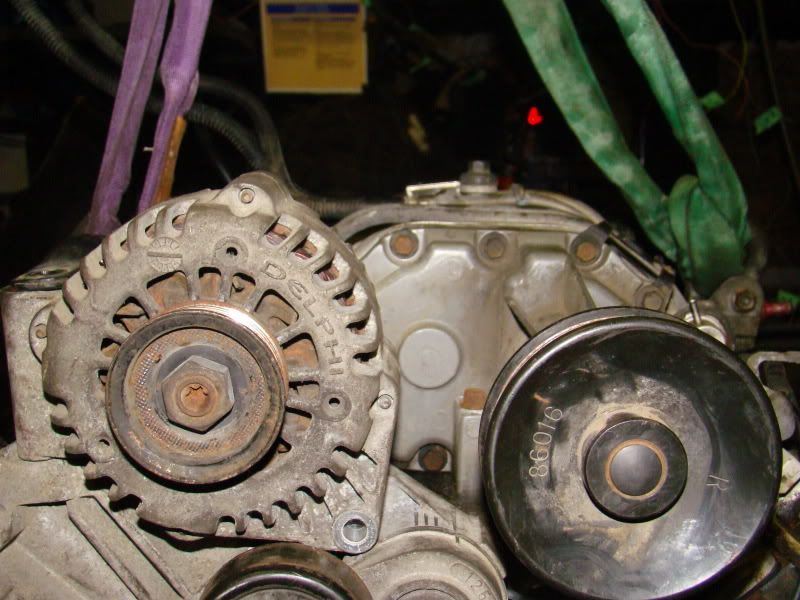
The alternator can be left up in the factory location but it hits a brace under the deck lid. So you either have to move it down or notch out the brace. I made a mount in about hour moving it down to were the power steering was.
That shock on the back side is pretty much good for nothing you can build a solid mount in its place, put dogbone up top or do both.
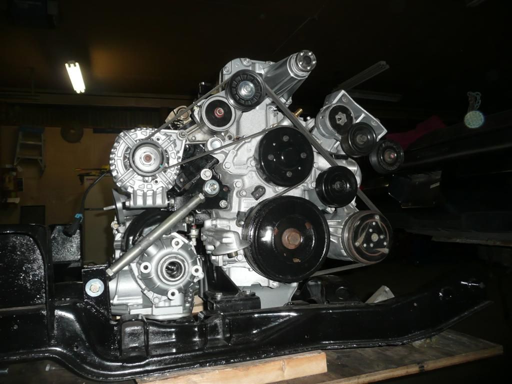
why would I have to relocate my alternator? It looks like it won't be much higher than the plastic cover.
Our work was on a series 1. The alternator looked like it should fit just as it does in your picture. But the structure of the trunk lid has a brace going right through that area, where the plastic piece is missed. Notching would be quickest, but we didn't want to do that. We elected to make a bracket.
What about the bracing for the back left? I'm worried that when the cradle is bolted the engine will flop around as it did while hanging from the hoist when I found this out. I could post a vid if it helps?
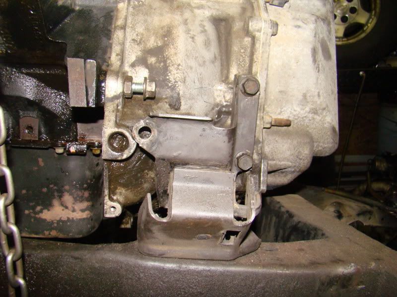
the motor is mounted with 1 mount on the oil filter side and 2 on the transmission, then a dogbone up top to keep the motor from twisting. Have seen a mount built on the bottom where the air conditioner mount. Like the ones pictured here http://www.gmtuners.com/Cus...88_GT_L67/index.htm.
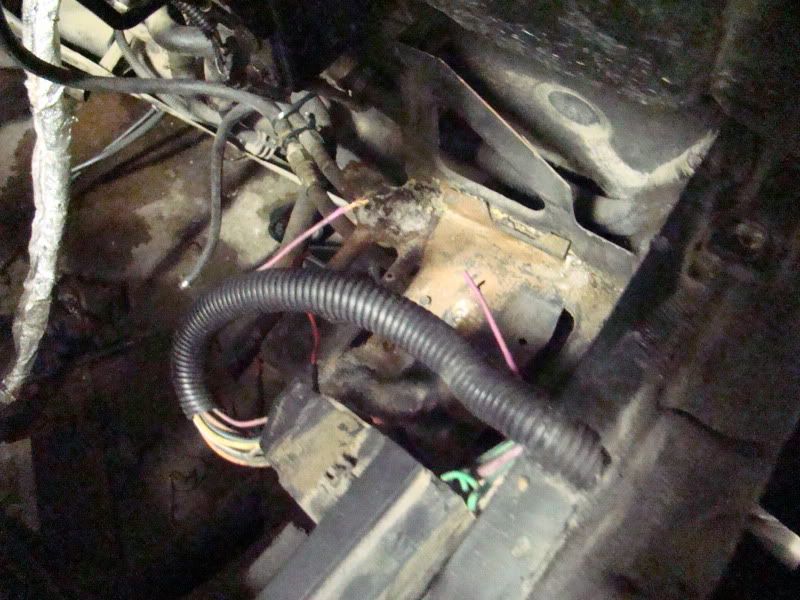
I also noticed on my c500 harness, the side that's attached to the car; the po cut the purple wire. I can put it back together but why would it be cut?
Oil Pressure - If your 3800 oil pressure sender is not 3 pin you will have to replace it. If it is 3 pin it might work. Center Pin - Wires to C203 - Oil Pressure Gauge Outside 2 pins - Wires to the CONTACTS of the fuel pump relay (Orange/Black and Tan/White) to provide a back up to the fuel pump relay closure
Heated O2 sensor pink - switched power C203 pin K - if it is too short extend it
Alternator Red - Goes to the PCM Orange - Goes to unswitched power
Ignition Harness Pink - Switched power to the ICM. Run this off of E3 of C500. If the donor harness doesn't have a fusible link you should add a 20A fuse located at C500
Evap Purge Solenoid (Pink and Dk Green/White wires) - Keep the solenoid - Move it physically to on top of the tranny. One vacuum line runs to one of the vacuum only ports (between the throttle body and the SC, or on the throttle body itself). The other vacuum line runs to the PURGE port of the evap canister Pink - Switched power - C203 pin K Dk Green/White - PCM
MAF Pink - Switched Power - C203 pin F Black/White - Connect to your Sensor Ground lug. (Use separate grounds (separate terminal rings on separate bolts) for the Relay Grounds and the Sensor Grounds)
Sensor grounds are normally Black/White wires Relay/Power grounds are normally Black only wires
Fuel Pressure Pink - There is no fuel pressure sensor so IDK
A/C Green - Runs to the A/C relay
Injector harness. I doubt the injector harness works the way it came from the donor engine. Cut the pinks and splice all the pinks from each bank to a wire. Then run those two wires to C203 pin J. Since these splices are outside you MUST use solder and shrink tube on the splices. You really need to use solder and shrink tube on all your splices.
Cut Purple wire near C500
If your body harness is for an automatic, the power to the starter solenoid will be on C500 pin A4. If it is for a manual the pin is E2. If the harness was for an automatic, then the wire on A4 is Yellow and it ran to the automatic transmission selector switch. When the tranny is in P or N the fat Yellow wire is connected to the fat Purple wire. The fat Purple wire then runs to the starter solenoid.
If your engine harness was only for a manual transmission then you should have a fat Purple wire that runs from E2 directly to the starter.
Phonedawgz, thanks again. I was a bit mixed on my terminology with the oil pressure and the oil pan sensor. Both have two wires and the black/white is cut which you explained where they go. As for the pressure sensor, yen mine is a 2 wire. Do you happen to know which sensor and i guess a new pigtail connector that I would need? And the pan sensor (low oil?), does that go anywhere in peticular or is it not needed? The fuel pressure i was confused about I now know is the boost solenoid, I have deleted that so I won't need the wiring. The injector harness, all the pinks are together; the pink I was referring to was one coming from that cluster. So with that I guess I run that single pink to the C203 J.
The oil pressure sender needs to be a 3 pin type. A replacement sender for an ’88 2.5 or 2.8 Fiero is what you need. Delco 1808A or 12555492 or equivalent.
PM sent re connector for the oil pressure sender connector - I have new 3 pin connectors and can sell you one with longer pig tails.
Drop the oil level sensor in the oil pan. There is no place to connect it to on the Fiero. Besides if you need an oil level sensor to tell you your oil is low you shouldn't be driving a Fiero.
It looks like your body harness was originally for a MT??? That wire should be yellow in a AT car. It is purple in a MT car. Maybe the previous owner didn't know that the starter wire showed up on a different pin for the AT and just spliced around the connector. I can sell you a short wire pigtail so you can put that wire back into C500 where it is supposed to be.
I can also sell you any other connectors you need. I have new 2 Bar MAP sensor connectors. It seems like the white connectors are always broken on the donor harness.
A few more things -
That extra connector in the CTS - eliminate it. Splice the wires direct. The Yellow and the Black wires need to run to the PCM. The Green wire runs to C500.
There is an extra connector in the Bank 2 (rear) knock sensor. I usually eliminate that also. Note also - that larger connector of the extra connector kinda looks like it would plug on the knock sensor directly. It doesn't. It doesn't fit anything but the socket for the extra connector and then the pigtail off of that it what actually fits the knock sensor.
You usually need to add a wire to pin E of the engine side of the 8 pin ICM harness to engine harness connector. That wire runs to the tach via C500. I can supply you with a wire with the proper terminal that will click directly into there. Remember at the ICM connector - The Pink (power) and pin E White (tach) run to C500. The other wires including the other white wire run to the PCM.
Transmission selector switch - The white 4 wire smaller connector wires to the PCM. The larger connector wires to the starter circuit, and pins B & E wire to the back up light switch. Some donor harnesses come with a nice connector there that have long fat wires for the starter connection. Some however come with just a few light wires there and relays are used for the heavy current switching. If you have the light wire type, I can sell you a connector wired with the fat starter wires and with new back up wiring added to it.
Relays (Fuel Pump and A/C) - I usually use the sealed new style relays. The Fiero relays are light weight and non-sealed. I can sell you replacement relays and sockets that fit on the stock hangers. See here - https://www.fiero.nl/forum/Forum2/HTML/121280.html
------ Also - You are going to need a speedo buffer circuit
The 4T65E has a VSS that puts out 24000 PPM (pulses per mile) square wave. The Fieros all had VSSs that put out 4000 PPM sine wave. The solution is to run the VSS signal directly to the PCM and then use the 4000 PPM square wave signal out of the PCM. Then run that square wave signal into a buffer and the sine wave buffer output can be fed into the speedo signal of C203. You can make your own (schematic on gmtuners.com) or buy mine - http://www.reddevilriver.com/Related_Products.html
----- Someone asked - I always build in the speedo buffer in the harness when an updated (non-TH125C) automatic transmission is used. I give it as an option when a manual transmission is used. The plus in running the VSS through the PCM when using a MT is that the PCM can be programmed to correct any speedo variances due to tire size. The minus is that the wiring is a bit more complicated and the PCM must be programmed for the 4000 PPM input for the speedo to not read 1/6th of the actual speed. All 3800 S2 PCMs were programmed as 24000 PPM from the factory.
[This message has been edited by phonedawgz (edited 09-23-2012).]
Phonedawgz, the car was originally a standard but for some reason the po only knows, it was changed to an auto. Next winters project will be changing it to a 5 speed. For that purple wire, since I will be going back to a standard, should I reconnect that wire back together? Do I need to change out my map? If so then I'll need a sensor replacement number to go with your harness. What is the CTS you speak of? Should I remove the second knock sensor and put a bolt in there?
At C500 GM put the starter wire on a different pin for a MT vs an AT. The PO instead of moving the wire in one of the connectors to match the other connector instead spliced the wire around C500. It doesn't matter which pin you use in C500 as long as the wire in the other connector goes to the same pin.
I would put the wire back into the C500 connector so you don't have to splice and cut the splice every time you disconnect the connector. It's fairly easy to put the wire back to the connector.
If you have a 3800 SC (not NA) then it came with a 2 bar MAP sensor. The connector for the MAP sensor is usually a 3 pin white tower type connector. (96 - about 2002) That white connector is broken in about 75% of the donor harnesses that I get. That is why I have new MAP sensor connectors.
(not my image, but this is what my 2 Bar MAP sensor connectors look like)
Later GM changed to a different 2 Bar MAP sensor that uses this connector
No you don't need to change out your MAP sensor. If you have the tower type connector and the connector tab is broken then you can replace it with my orange one and still use your MAP sensor. If you have the gray type connector then it most likely is not broken. Electrically both sensors are the same. There is no advantage to swapping to the newer stype MAP sensor, unless you just wish to buy one for $65+.
------- CTS = Coolant Temperature Sensor. It is the 3 pin connector located right below the thermostat/water outlet near the alternator. Most (all?) 3800 SCs come with the 3 pin combo CTS (for the PCM) and TEMP Gauge sender. The Yellow and Black wires connect to the CTS itself and wire to the PCM, The green wire connects to the temp gauge portion of the CTS and wires to C500. Also sorry for the confusion since we call the 3 wire CTS a CTS since it is actually a combo CTS and Temp Gauge Sender.
3 wire CTS connector
----- Knock sensors -
No don't remove it. You need both sensors, one for each bank. The front one uses a dark blue wire. The rear one uses the light blue wire, but there is usually that extra pigtail thing on the wire that confuses many.
This connector will not plug into your rear knock sensor - it only plugs into the pigtail connector
This is the type of connector that will actually plug into your rear knock sensor
[This message has been edited by phonedawgz (edited 09-23-2012).]
Phonedawgz. I have a 2002 3800sc. I do have the white map sensor but I won't need a connector as a couple years ago I bought a 2 bar with connector for my 2000 silvy but got the wrong sensor and had to order the one from the sc cobalt. So my hoarding skills finally came to good use.
Back to it finally, got the headers and transmission crossover wrapped and put back on. I was hoping to get away with out putting on the coil bracket but I see now that it houses a few idlers. I also got rid of the a/c tht came on the motor. I'm looking at putting the coils either at the battery location or possible along the fender on the drivers rear somewhere. I want to get rid of the doggone off the coil bracket, I see it could be cut off. What is the most that could be cut off or what have y'all done, pics please. I will get rid of the other dog bone mount. I'm keeping the alternator in th stock location so with that, what can I do about a dog bone?
------------------ 86 GT Convertable 3800
[This message has been edited by Tweeder (edited 03-03-2013).]
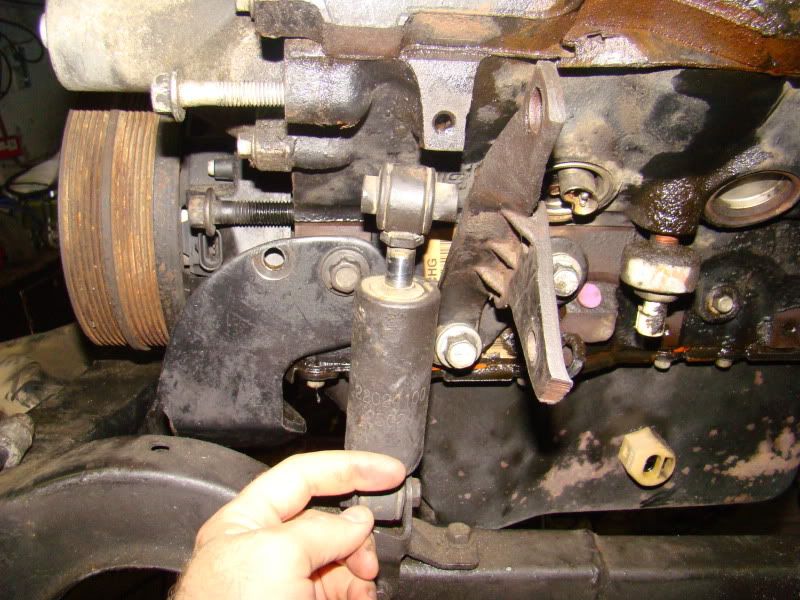
I cut down the coil bracket, would have been nice to get rid of the whole top part. I also use the dog bone bracket from next to the thermostat housing and modified it to fit here.
I had to drill out the holes bigger and ground out the outside bottom so it would get closer and ground out above the bottom hole to clear as well.
I also had to grind out the bone mount a little to clear a bolt so it would sit flush.
Not sure how it will work until I get to in the car. Its lower than stock but I can fab up a bracket and weld or bolt it through the trunk wall.