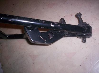
Here's some pictures of the a-arms from the crossmember I made: This is the sealing plate for the Sweet rack that mates with the Fiero steering shaft cover:
IP: Logged
10:12 PM
toddshotrods Member
Posts: 1177 From: Columbus, OH, USA Registered: Aug 2004
I believe it's eventually gonna happen, but it's also gonna take a while. R Runner's car is already built and he's busy working to take care of his family. Gusshotrod has his hands full building his car, which is using a totally different suspension system.
My car is yet another independent effort that is taking a lot of my time to finalize the design plans.
That means we all have a lot on our plates, but eventually, we should have enough information and a little time to develop a bolt-in system for the Fiero that brings its handling into the 21st century.
What's really needed is more people to get involved in the process. People who would actually need and use the system. Research is the main thing that is needed right now, and it is very time consuming.
------------------ Todd Perkins - the member formerly known as "perkidelic" todd's hot rods
I'd like to see those anti-dive blocks made for the front crossmembers. Solid blocks of steel? I have the steel 2" drop spindles from Street Dreams. I also have 300lb front springs that I cant install using normal spring compressors. The bumpstop gets in the way when using those compressors. Any ideas would be appreciated.
IP: Logged
07:09 PM
R Runner Member
Posts: 3703 From: Scottsville, KY Registered: Feb 2003
Work had me busy but is starting to lighten up. I actually got a chance to get the suspension analyizer running from performance trends. If any one is willing to take the data, I can plug it in and we can see what the wheels will do under several conditions including dive, percent turn in, and sway all at the same time. If you do go to the trouble, please give me time to input the dat. It is not much effort, just finding the time.
Here is what I need to run the software. Don't use the example, it is not optimized.
All points are measured in X,Y, and Z from a given point. At some point, I will input the data for the IMSA and find out why it handles so well.
Paul
IP: Logged
07:38 PM
Feb 4th, 2005
Will Member
Posts: 14303 From: Where you least expect me Registered: Jun 2000
I'd like to see those anti-dive blocks made for the front crossmembers. Solid blocks of steel? I have the steel 2" drop spindles from Street Dreams. I also have 300lb front springs that I cant install using normal spring compressors. The bumpstop gets in the way when using those compressors. Any ideas would be appreciated.
I'd like to see them, too... but finding the time is the interesting part...
Will most likely be aluminum, not steel.
300# is a bit much for a front spring. What are you running in the rear?
Compress it outside the car, then wrap a couple of turns of heavy mechanic's wire around the coils at 3 or 4 places around the circumference. Install and bolt everything together, then reach in with cutters and carefully cut the wire, then pull it out. Obviously don't wrap the wire aroung the very ends of the spring or you won't be able to get it out. Wrap it from one coil shy of one end to one coil shy of the other end.
Originally posted by Will: 300# is a bit much for a front spring. What are you running in the rear?
Compress it outside the car, then wrap a couple of turns of heavy mechanic's wire around the coils at 3 or 4 places around the circumference. Install and bolt everything together, then reach in with cutters and carefully cut the wire, then pull it out. Obviously don't wrap the wire aroung the very ends of the spring or you won't be able to get it out. Wrap it from one coil shy of one end to one coil shy of the other end.
300lbs sounds more like a rear spring to me! That's a heckuva lotta spring for the front?!?! I was accidentally given a set of full size Chevy springs for an S10 that I was lowering once. The instructions said, "the spring may appear to be of a heavier gauge and longer than the original - that's OK, they WILL lower your truck." I couldn't get them in so I went to a spring shop and had them banded. It only cost a few bucks and they compressed and tied each spring with a steel band, just like Will suggested, just with a crimped steel band instead of mechanic's wire.
When I got back to the shop the springs popped right in place. I locked up the ball joints and put the torch to the bands. The truck jumped OFF THE JACKSTANDS!!!!!!! Not off as in it hit the floor, but it cleared them by half an inch and settled back down on them. Same thing on the other side. It sounded like a high-powered rifle going off.
I put the wheels on and let the truck down and it was two inches higher than stock with two-inch dropped spindles! I had to drive it home that night and it was like having a solid mounted straight axle with NO springs! I called and they figured out what the problem was and next-dayed me a set of the right springs. At first they tried to tell me it would "settle"! It was an adventure to say the least! I can't remember how we got them back out.
The moral of this story... Make sure you have the right springs for your application.
------------------ Todd Perkins - the member formerly known as "perkidelic" todd's hot rods
IP: Logged
11:01 AM
toddshotrods Member
Posts: 1177 From: Columbus, OH, USA Registered: Aug 2004
Paul, I can get a lot of the specs you need from my spare front suspension but my problem is the same as everyone else's - time! It's this pesky thing about keeping food on the table
IP: Logged
11:04 AM
PFF
System Bot
Feb 6th, 2005
cadero2dmax Member
Posts: 1266 From: Brighton, CO Registered: Oct 2001
300lbs sounds more like a rear spring to me! That's a heckuva lotta spring for the front?!?!
Your adventure sounds like they sold you the wrong height springs, it wasn't the spring rate that caused your problems. As long as you have the right spring height, you can go as stiff or as soft as you want and not affect ride height.
I have 400lb Hypercoil springs on the rear and 325 custom made (stock ride height) springs on the front on the Cadero. Anybody at Wheatstock saw how flat the car cornered under full acceleration with that set-up - of course, the rest of the suspension has been tweaked a little also . The Greg Duncan built suspension has no adverse bump steer with the '88 cradle and 2" raised roll center, BTW.
The Cadero doesn't ride as smooth as my Lincoln LSE on the city streets with this set-up by any stretch of the imagination. But it isn't as harsh as you would believe.
Check it out at the track day at Arroyo Seco this summer.
G
[This message has been edited by cadero2dmax (edited 02-06-2005).]
IP: Logged
09:45 AM
toddshotrods Member
Posts: 1177 From: Columbus, OH, USA Registered: Aug 2004
Thanks for the info G. I guess it's the fact that the Fiero has decent f/r weight distribution. I know 300lbs isn't a really high spring rate, it just sounded high for a street driven car. Mainly because there isn't much up there. My nose-heavy Camaro, on the other hand, will be getting a pair of 600 pounders up front.
The springs on my S10 were too high of a rate and too long. I like a really sporty ride and usually favor a higher spring rate, but these were ridiculous. With the truck fully assembled there was NO bump travel. There simply wasn't enough weight on the front of the truck for the spring rate. They were sport coils for a 3-inch lowered full size Chevy pickup. That means they had a significantly higher rate than even a stock full-size spring. When I got the right springs in, the ride height was perfect, as was the ride and handling - a little stiff, but flat and stable.
Your car sounds like fun. I wish I could be there to see it, but I won't
------------------ Todd Perkins - the member formerly known as "perkidelic" todd's hot rods
[This message has been edited by toddshotrods (edited 02-06-2005).]
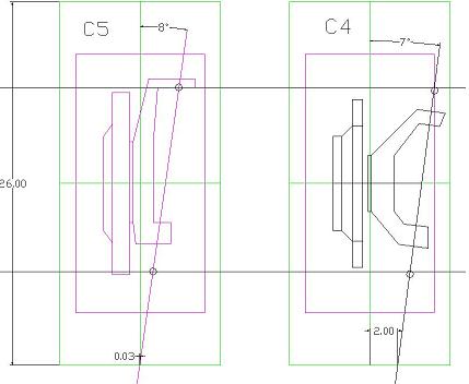
Just some info: C4 rear hubs are about .010 larger diameter than C5 front hubs where they center in the spindle. Both have a triple bolt pattern with the C4 about .3 larger circle. C4 rear hub has .75 more off set than the C5 front. You could mount the C4 hub into the C5 spindle by enlarging the ID of the spindle about .010 in. and slotting the mounting holes in the hubs. Neither item whould require a machine shop. You would end up with about .75 kingpin offset (good) and would be cheap. King pin angle looks like 8 degrees. Brand new aluminum spindle and hub with very good geometry for about $300.
Thanks five million gusshotrod!!! I have been planning on using this exact combination for over a year now. I had a feeling it was going to turn out to be a good combination, from seeing some of the specs on the parts.
It would be interesting to see if this could be packaged under stock bodywork, on an unmodified space frame. Bolt-in crossmember, stock inner fenders, etc. Getting the UCA's located for decent geometry would probably be a challenge, but the price is right if it's possible.
------------------ Todd Perkins - the member formerly known as "perkidelic" todd's hot rods
"spare time" eh? I've heard of the stuff, but it seems to have originated from the same people that started the pot of gold under the rainbow stuff. I haven't had much luck finding that yet either, but I'm stilll lookin'
"spare time" eh? I've heard of the stuff, but it seems to have originated from the same people that started the pot of gold under the rainbow stuff. I haven't had much luck finding that yet either, but I'm stilll lookin'
LMAO so true
after I get my engine in I have 4 main fabircation projects.. my konigseg VDC hinges (for fiero), the custom stearing knuckles, and a custom interior, and custom bodywork. probably in that order.
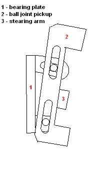
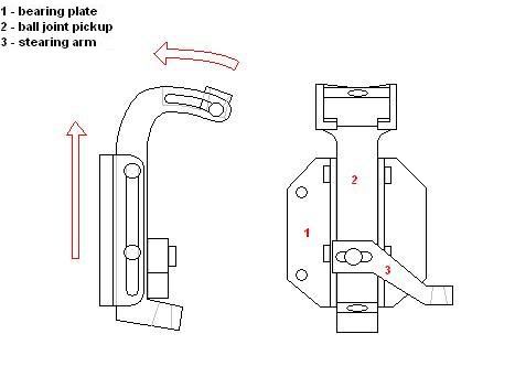
well, i got to thinking about wills modular knuckle and how he mentioned keeping the steering arm in line with the lower ball joint. (i dont know why more cars arent doing this). those ideas smudged around in my head and something finally started to make sense. then i went out to the back shop and cnc'd some billet aluminum parts. . . . well, its just lumber ideas, but it was fun. here they are.
it is 1.5" "aluminum" 9.5 tall, 8" wide. the lower ball joint goes in at the bottom of the knuckle. the slot in the knuckle is where the castle nut is and should allow room to get a wrench in. the upper mount has three positions.
the entire assembly is rocked back at 9* of caster. i just guessed you guys were thinking of 2* or 3* of anti dive (thanks for some education) total caster 6* or 7*.
SAI changes slightly with upper ball joint repositioning, but should be real close to 9*. SAI can be changed by shimming behind the upper ball joint mount.
the lower ball joint is so far out, it will need something like c5 rotors for clearance. they have very little "hat" and a wide open center area. i dont have a c4 hub to test scrub angles, but it sure wont need a high offset wheel. it may be too close.
the steering arm is tipped down to line up with the lower arm axis. the tie rod end will go in the bottom. the rack will have to be lowered alot, and the subframe will probably be in the way some. the front arms on the early years dont extend much in front of the center of the wheel, so there should be room for the rack just in front of the subframe. the steering arms are slotted, i agree with will that holes would make life alot easier for repeatability, but it seems that even two holes would be spread too far apart to make good choices.
ackerman angle can be changed by shimming behind the steering arm (and some by moving in the slot).
the whole back portion of the main plate is unfinished because it really needs to be shaped for caliper mounts. ??
the same parts could be used for R and L. they could possibly be used for the rear as well by turning them around and using a longer upper ball joint mount piece with two ball joints on the outsides of the bolts in conjunction with an upper control arm. this would give you camber on compression and completely eliminate bump steer. it would also work with the exsisting lower arm. after you corrected the pro squat stuff. simple plans could be shared with individuals and sent out for machining for very little $
please share what you think will need changing, or why it just wont work.
sorry to be so looooong winded, but there is one more thought i had to share.
changing the pro dive angles on the early models.
will mentioned lowering the subrame to change the angle of the pivot points. what if you shimmed just the front edge of the subframe, twisting it in the proper direction. then take the other idea and move the rear pivot point up "x" inches. the upper arm stays parrallel. the subframe doesnt drop to any degree. there would be some slotting and reshaping around the upper part of the subframe mounts, but i think it should all fit.
add the upper held arms, lower rcc arms, coilovers - like will said. then change the upper ball joint position to get the camber swing you want . . . what else?
[This message has been edited by ricreatr (edited 02-11-2005).]
As to antidive, 2-3 degrees is also what I was thinking. The rear of the crossmember will have to move down to achieve this, and some kind of bracket will be needed to position the rear of the lower a-arm downward. Looks like you put some thought into this.
[This message has been edited by gusshotrod (edited 02-11-2005).]
IP: Logged
11:52 PM
Feb 11th, 2005
Will Member
Posts: 14303 From: Where you least expect me Registered: Jun 2000
This is very close to what I was thinking of. I'd prefer a bolt on LBJ boss similar to the UBJ boss... Making the LBJ adjustable for height would essentially give the car adjustable lowering knuckles...
The steering arm mount still needs thought to give and easy way to correct the bump steer after a change of the castor adjustment...
in an effort to get the longest arms, and the least offset, the adjustable lbj mount was given up in that idea. it is not as convenient, but you would have to get a new main plate for ride height adjustment. it is, by nature, lower already. hmm adjustable lbj . . .
what are your ideas for steering arm adjustments? never even thought about that. wouldn't most everyone be close to 6*? by replacing the rod end with a heim joint, you could use shims to adjust. ????
IP: Logged
02:01 PM
Will Member
Posts: 14303 From: Where you least expect me Registered: Jun 2000
Shimming the joint is the conventional method, but it is time consuming and has to be redone EVERY time you have the castor adjusted.
The camber setting that feels the best at the limit of front tire traction may not be 6 degrees... With a contact patch 6" long and a tire 24" in diameter (and a knuckle with which the kingping axis and wheel axis intersect), I'd start the search for a good castor angle around 5.7 degrees... but I really have no idea if that's a good guesstimate of the contact patch length or not...
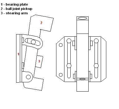
here it is with the 1.5" (in addition to whatever it was already lowered) lowering blocks. i have moved the steering arm angle to make up for the errant anti-dive setup from before. four bolts go in from the bottom and up to the knuckle. im wondering how much unsprung weight all the adjustibility is costing.
IP: Logged
09:33 PM
Feb 12th, 2005
Will Member
Posts: 14303 From: Where you least expect me Registered: Jun 2000
Prolly not much weight if it's thought out thoroughly enough... maybe you could use balsa instead to reduce unsprung weight...
I'm not wild about the little window for tightening up the LBJ nut... Even seen a Held lowering knuckle? They have something similar for getting to the LBJ nut... It's a complete pain in the @$$ to work on... And since this is being designed for a semi-race car that will get worked on a lot, it needs to be easy to work on.
well, i got to thinking about wills modular knuckle and how he mentioned keeping the steering arm in line with the lower ball joint. (i dont know why more cars arent doing this). those ideas smudged around in my head and something finally started to make sense. then i went out to the back shop and cnc'd some billet aluminum parts. . . . well, its just lumber ideas, but it was fun. here they are.
it is 1.5" "aluminum" 9.5 tall, 8" wide. the lower ball joint goes in at the bottom of the knuckle. the slot in the knuckle is where the castle nut is and should allow room to get a wrench in. the upper mount has three positions.
the entire assembly is rocked back at 9* of caster. i just guessed you guys were thinking of 2* or 3* of anti dive (thanks for some education) total caster 6* or 7*.
SAI changes slightly with upper ball joint repositioning, but should be real close to 9*. SAI can be changed by shimming behind the upper ball joint mount.
the lower ball joint is so far out, it will need something like c5 rotors for clearance. they have very little "hat" and a wide open center area. i dont have a c4 hub to test scrub angles, but it sure wont need a high offset wheel. it may be too close.
the steering arm is tipped down to line up with the lower arm axis. the tie rod end will go in the bottom. the rack will have to be lowered alot, and the subframe will probably be in the way some. the front arms on the early years dont extend much in front of the center of the wheel, so there should be room for the rack just in front of the subframe. the steering arms are slotted, i agree with will that holes would make life alot easier for repeatability, but it seems that even two holes would be spread too far apart to make good choices.
ackerman angle can be changed by shimming behind the steering arm (and some by moving in the slot).
the whole back portion of the main plate is unfinished because it really needs to be shaped for caliper mounts. ??
the same parts could be used for R and L. they could possibly be used for the rear as well by turning them around and using a longer upper ball joint mount piece with two ball joints on the outsides of the bolts in conjunction with an upper control arm. this would give you camber on compression and completely eliminate bump steer. it would also work with the exsisting lower arm. after you corrected the pro squat stuff. simple plans could be shared with individuals and sent out for machining for very little $
please share what you think will need changing, or why it just wont work.
thanks, Jarret
looks like fun - maybe I should do that to demonstrate my idea after a few alterations
oh, please do!! and like the man said, utilize the latest in balsa!
i spent half the day sunday and a portion of the workday monday thinking about the sketch you had posted. imagine pooh bear with paw to head . . . "think, think, think". nothing happened. and i was ready to brake out some aluminum for a mock up too.
will, with much drop built into the mockup, the lbj nut can be accessed from the outside of the knuckle. pretty easy. the logical option would be going for heim joints. one bolt, from the underside (or top). ive seen it done, but is there a type joint that is best suited to bearing all the force of the shock? or do they just work fine? cant think of any method to keep bumpsteer from changing with caster. i feel stupid saying it cant be done . . . do you have an idea? cant imagine changing caster often, or it mattering much either. but if it is a race car, then someone is going to spend a little time charting out how much to shim for every degree of caster, and it would be a quick deal.
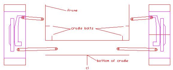
for lowering the suspension, ive come across a lot of problems. just moving the hub mount up, means the lbj goes down and out. both cause interference with the rotor. you have been talking about a new crossmember anyway, should the arms themselves be located higher instead? keeping the lbj close to the hub seems like the best way to get long arms/reduce scrub. another option is to move the entire subframe up to drop the car. according to the manual there is close to 6 1/2 inches between the subframe mounting surface and the bottom of the chassis (page 3j-6). subframe four inches thick, designed with 2 1/2" drop, you could easily put blocks in the mounts to get any ride height from stock to (no shims) 2 1/2" drop. all geometry stays the same.
anyone interested in checking out the c6 knuckles?
oh, please do!! and like the man said, utilize the latest in balsa!
i spent half the day sunday and a portion of the workday monday thinking about the sketch you had posted. imagine pooh bear with paw to head . . . "think, think, think". nothing happened. and i was ready to brake out some aluminum for a mock up too.
will, with much drop built into the mockup, the lbj nut can be accessed from the outside of the knuckle. pretty easy. the logical option would be going for heim joints. one bolt, from the underside (or top). ive seen it done, but is there a type joint that is best suited to bearing all the force of the shock? or do they just work fine? cant think of any method to keep bumpsteer from changing with caster. i feel stupid saying it cant be done . . . do you have an idea? cant imagine changing caster often, or it mattering much either. but if it is a race car, then someone is going to spend a little time charting out how much to shim for every degree of caster, and it would be a quick deal.
for lowering the suspension, ive come across a lot of problems. just moving the hub mount up, means the lbj goes down and out. both cause interference with the rotor. you have been talking about a new crossmember anyway, should the arms themselves be located higher instead? keeping the lbj close to the hub seems like the best way to get long arms/reduce scrub. another option is to move the entire subframe up to drop the car. according to the manual there is close to 6 1/2 inches between the subframe mounting surface and the bottom of the chassis (page 3j-6). subframe four inches thick, designed with 2 1/2" drop, you could easily put blocks in the mounts to get any ride height from stock to (no shims) 2 1/2" drop. all geometry stays the same.
anyone interested in checking out the c6 knuckles?
good points
a quick change to the design
or maybe
[This message has been edited by Kohburn (edited 02-15-2005).]
ohhh yeah, theres some progress! i aint tryin that in wood though!! i like A alot.
what are your plans for hubs? i can see eight of them on the bench from here, and they all require a hole in the mounting plate for the "rest" of the bearing to protrude through?
[This message has been edited by ricreatr (edited 02-15-2005).]
here is the current project in the garage N* with getrag and holly comander CPU # 950 maybe NOX or tiny twin turbos tube headers & big ext system tube A-arms with coilovers 13" vett brakes and twin puck calipers gutted body 86gt maybe choptop 18" rims with race tyres
some accembly required
hope to have it running under 10k total
------------------ Question wonder and be wierd are you kind?
Ok, this is cool. C5 front suspension geometry will fit into Fiero. Upper A-arms are almost 8 inches long. Steering is Mustang 2 with zero bump, RC is two inches, rim width is 8.5, ground clearance is 4 inches. Spindles have two existing holes to bolt on a new steering arm. A wheel wider than this could probably be used because the pivot point is moved outward.
[This message has been edited by gusshotrod (edited 02-15-2005).]
IP: Logged
08:22 PM
toddshotrods Member
Posts: 1177 From: Columbus, OH, USA Registered: Aug 2004
I am assuming you narrowed the width (hub-to-hub) to the the same as the Fiero's, correct? What effects did this have on the geometry? Are you using the same heights on the control arm pick-up points, as the Vette geometry?
I knew it would be possible to fit the LCA's,but I wasn't sure if the UCA's would clear the frame - great work! How about the inner fender? I have them cut out on my car so I wouldn't have anything to measure to see. Pretty interesting that this could be such an easy bolt-in conversion for Fiero enthusiasts.
------------------ Todd Perkins - the member formerly known as "perkidelic" todd's hot rods
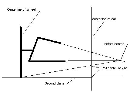
WIdth is stock fiero. Inner fender wells will fit with some trimming around the top of the cradle. C5 geometry is in the ratio of the upper a-arm length to the lower a-arm length, the spindles, and the roll instant center length. Roll center and anti-dive can be put where ever you want it. Steering "speed" can be adjusted with the length of the steering arms.
that would be awsome. when you say steering is mustang2, are you refering to the rack? and with the two holes in the spindles, you are just going to bolt in your own arm?