* DETAILS WITH PICS OF COMPLETE FRONT END REBUILD START ABOUT MIDWAY DOWN IN THIS THREAD *
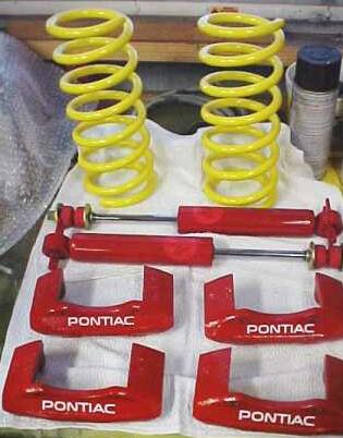
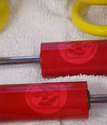
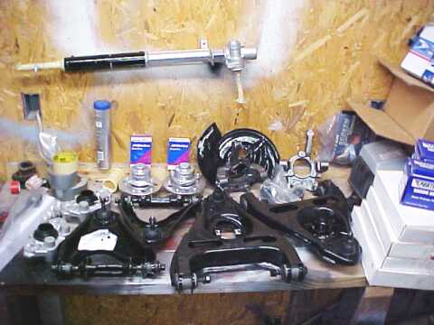
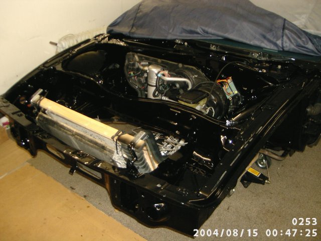
I am going to try and post pics as I move along. This will be a slow progress for me so I will add it to my Favorites ( Thanks Cliff for a great add-on) that way I will remember to pull it up and post whenever I get some more time to work on it. Everything is in, just need some time and to finish up some odds and ends like cleaning the underneath of the car and maybe some painting. I can only work on the weekends so bare with me. All the parts in the pic. are ones I removed from a parts car 88 and refurbished. Except Shocks are KYB that I repainted and added the Fiero Logo.
Pics coming next post
[This message has been edited by Zoom88 (edited 09-08-2004).]
The Springs are off the 88 parts car,( I saved the set for the Formula) The parts car was a 4 Cyl. They have been cut 1 coil, I then heat the last 4 " of the coil cherry red very quickly and then compressed the spring causing the heated section to bend till I got a measurement of 10 1/4" (also making the end sit flatter as it was originally before the cut) I had to only bend the end a small amout to get the measurement I wanted. I then let them air cool. This was over 6 months ago while I ran them to see how I liked them. When I pulled them to clean them up and paint them, they have not sagged and still measure 10 1/4" and I am very pleased with the out come. Thats why I am putting them back in.
[This message has been edited by Zoom88 (edited 08-15-2004).]
IP: Logged
07:07 PM
1MohrFiero Member
Posts: 4363 From: Paducah, Ky Registered: Apr 2003
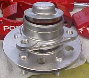
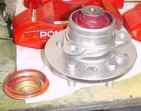
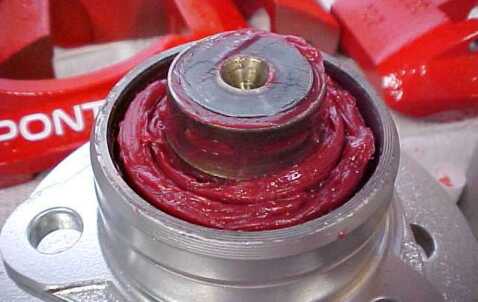
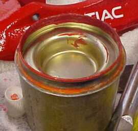
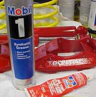
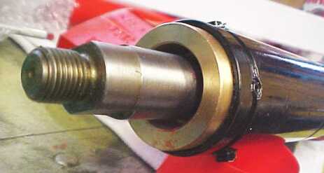
Ok, there are some who believe you can not repack a 88 Front wheel bearing. I am here to tell you there is absolutly no truth to that. I was a Millwright for a Major Chemical Company for 14 years. I worked on large Turbines and compressors, some with bearings that would dwarf one of the Fieros wheels. From pillar block, tilt pad , babbit rollor, etc; Some we had sensors on just to monitor there movement and temp. I still work for the same company but have moved on to another field. As you will see in the pics below, if you have a known GOOD bearing and just want to repack it you can. This will not fix a bad bearing !!!! Carefully pull the little cover, once the cover was off I rinsed all the old grease out using a parts cleaner and a brush, I rinsed it out 3-4 times blowing it dry with air each time until I was completely satisfied all the old grease and debris was gone. (Try not to turn the bearing much while doing this.) I then repacked the bearing using Mobil 1 synthetic grease. I packed it in by hand making sure I pressed it in between the bearing and race turning it occasionally as I went. I did this until I was sure it was well packed. Also you will notice on the lip of the little cover that was removed there was some type of orange looking sealant. I cleaned the lip real well and then applied a thin layer of High temp red silicone. This is the second time I have done this, First time on a set that had 92,000 miles on them. They are the ones on my car now and they have 162,000 miles on them. And the set I just did they currently have only 67,000 miles on them. If done as I have stated above this is a completely safe procedure.
[This message has been edited by Zoom88 (edited 11-30-2004).]
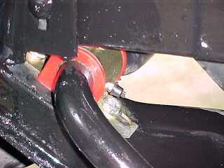
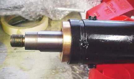
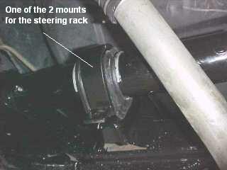
Here is a pic of Rodneys rack bushing installed for those who haven't seen one.
If you look close you will see it is held in with 2 screws, 180 deg apart as well as in the groove for the dust boot I recessed 2 rivets 180 deg apart.
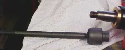
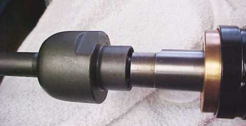
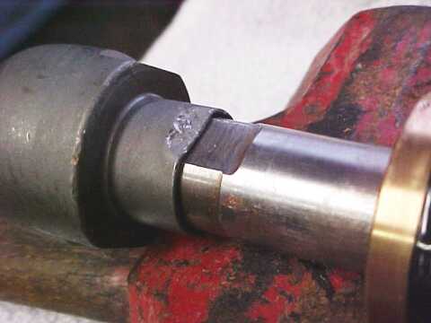
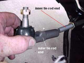
Below pic I am getting ready to install an inner tierod end
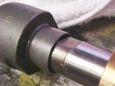
Make sure you bend the end down on the flat to lock it in place
[This message has been edited by Zoom88 (edited 08-21-2004).]
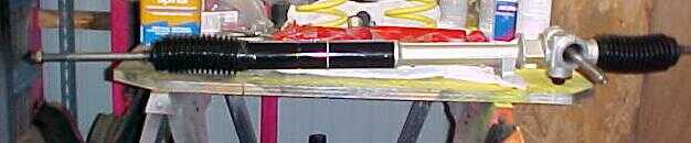
Rack complete and ready to install, ( will add the outer tierod ends after its installed)
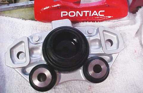
One of the Front Calipers I rebuilt. Edited because I wanted to add this after the fact. If I had it to do again I would have purchased new calipers from I think it is www.calipersonline.com Reason being parts ended up costing me almost the same amount, this included replacing the sliders and boots. (you can get 2 Front calipers for around a $100 bucks), and then I still had to do the labour.
Ok thats it for this weekend........not much response but I know there have been several people ask questions about an 88 Front end rebuild so I will keep posting as I go. Once I start installing parts maybe feedback will pic up !!!
[This message has been edited by Zoom88 (edited 08-21-2004).]
By the way I ordered All my Front end parts from Rodney. Great to work with and awesome prices......as well as everything fits like it is suppose to !!!!
It looks good Zoom. Now where I seen the greasable sway bar bushing before? Hmmmm.
As for the rack bushing it is advisable to put four (4) one way set screws in every 90 degress apart and not use Rodney's rivets. His will break. Many years ago a forum memeber posted that his broke using just the two supplied rivets and the end result he had an accident.
I autocross mine so for the strength the four lockscrews is best for the rack bushing.
Overall it looks great. Keep up the good work.
Thanks Solo2 , alot of the things I have done are from what I have learned from you and Ogre. For the street I like the Ogres suggestion of rubber bushings on the front A-arms and Poly everywhere else (including rear). But the rubber bushings are hard to come by for the lower control arm on an 88 and not really feasible, but I like the setup enough to do it again ....took me a long time to find 2 new sets. Just about everything else is adapted from your suggestions...I fiqure anyone autocrossing should have an idea what works and hears about what has been or is being tried and tested. On the steering rack I agree, 4 lockscrews is very secure. I am using 2 screws with locktite and 2 all metal rivets.
quote
Originally posted by fiero67:
I will be watching this thread. Im preparing to do this this winter. I like the detail on the shocks. Please do keep posting pics.
I will keep posting, if you would like more detail on anything feel free to Email zoom88@diginostics.com hopefully I will be able to help.
This is the 3rd time I have done a front end rebuild trying different setups. I believe I have finally put together what works for me !!
[This message has been edited by Zoom88 (edited 08-21-2004).]
IP: Logged
06:45 PM
Aug 22nd, 2004
Torch-Red87 Member
Posts: 314 From: Stuttgart, Germany Registered: Aug 2004
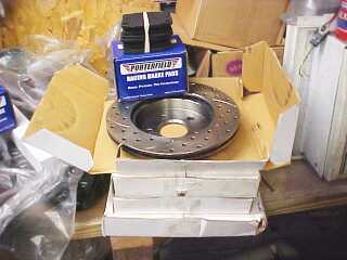
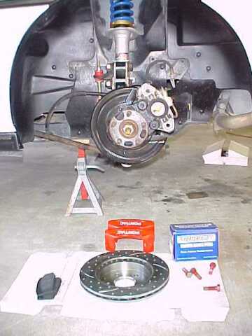
Don't have much time to work on the car this weekend. So I am not going to do anything with the front end but did install new brake pads and rotors on the rear this morning. All pics and instruction below are in reference to 88 rear brakes. Most the info is basic but if your new at it and don't know ...then it can be a real headache. Such as not having the notches on the face of the piston aligned correctly.
Everything laid out ready to get started !!
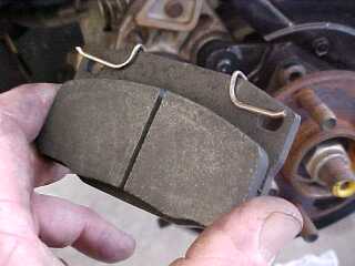
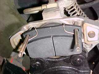
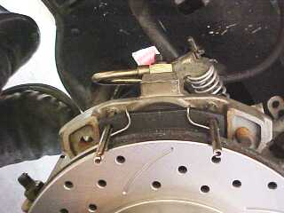
Correct way to install spring on pad
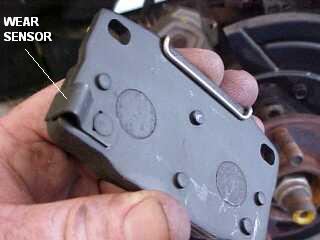
This is the inboard pad, it will be the one with the wear sensor
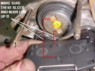
Before installing pad make sure the piston is all the way back and the slots are left in the right position so the nubs on the back of the pad will line up with them and seat properly. See pic below.
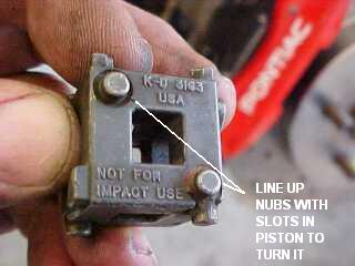
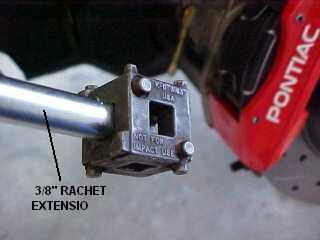
There are several tools available to do this. I like this little simple one.
Find the set of nubs on it that match the slots in the piston and then I just use a long extension with it to turn it with.
The piston screws in or out, Passenger side, screw it in clockwise to make sure piston is all the way back. Driverside is counterclockwise. Make sure you leave the slots in the piston in the right position as we dissussed earlier.
[This message has been edited by Zoom88 (edited 08-28-2004).]
Rotor Installed (When installing slotted rotors install on the side of the vehicle that results in the end of the slot nearest the outer edge of rotor always contacting the brake pads first. )
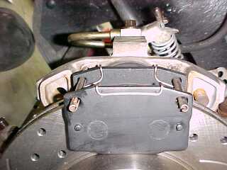
Outboard pad installed
Bridge (outer half of rotor installed)
Ready to go.
NOTE ** ROTOR IN PICS ABOVE IS INSTALLED ON THE WRONG SIDE OF THE CAR. THE CURVED GROOVES IN THE FACE OF THE ROTOR SHOULD BE GOING IN THE OPPOSITE DIRECTION. THERE ARE PICS LATER ON DOWN IN THIS POST THAT SHOWS THEM CORRECTLY INSTALLED.
[This message has been edited by Zoom88 (edited 09-10-2004).]
This is a GREAT write up. I'm glad I visit the chat section some now that I'm at college and can't work on my car. This is def. going to be saved as a favorite!! Thanks for taking the time to go into detail. --Bryson
This is a GREAT write up. I'm glad I visit the chat section some now that I'm at college and can't work on my car. This is def. going to be saved as a favorite!! Thanks for taking the time to go into detail. --Bryson
No problem, I remember how it is when trying to gather info the first time you take on something new !! Now if I can only remember to take pics. and unfortunatly I don't have a lot of time right now but I do try and get something done every week end. I will keep adding everytime I do get some more work done though !!
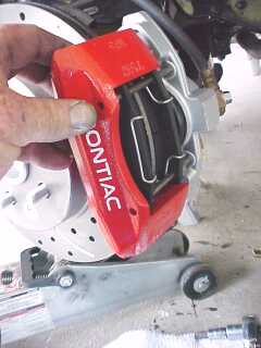
how did you get the pontiac wording on the calipers
They are decals I get from this place www.XenonMods.com/allcaliperdecals.htm He sends you 6 (incase you make a mistake) for $10.00 and will make what you want. He makes them special for calipers. Last set of calipers I had them on they held up better than the paint. In fact when I blasted the calipers to repaint them the decals were the hardest part for the bead blaster to remove. Anyway I first bead blast the calipers, then I paint them with Brake caliper VHT paint . Once it is good and dry I apply the decals and then I spray everything with a coat of clear.
[This message has been edited by Zoom88 (edited 08-28-2004).]
IP: Logged
08:51 PM
Aug 29th, 2004
Formula88 Member
Posts: 53788 From: Raleigh NC Registered: Jan 2001
Great write up!! The pics really show much better than a text explanation of how much easier it is to split the caliper rather than try to take out those freakin' spring pins. That's how I do my brakes every time!!
Great write up!! The pics really show much better than a text explanation of how much easier it is to split the caliper rather than try to take out those freakin' spring pins. That's how I do my brakes every time!!
+ for all the hard work!
Thank You, yes it makes it really simple and quick !!
Ok, this will be the last of the pictures. Finally had time to complete the frontend work this weekend. Please NOTE - Not all steps have to follow this particular order. This is just the way I prefer doing it.
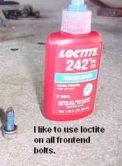
I use Loctite on everything !!
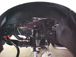
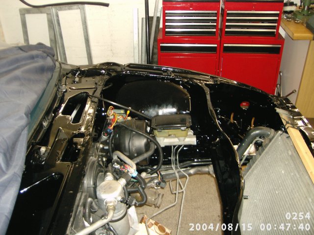
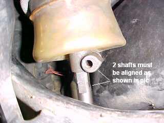
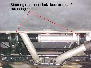
First think I did this weekend was install the steering rack. Before you bolt rack up you will first need to line it up with the steering column shaft and connect it first.
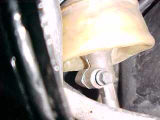
There are only 2 mounting brackets and 4 bolts that hold the rack in. I changed both rubber mounts on the brackets.
[This message has been edited by Zoom88 (edited 09-06-2004).]
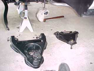
Ok we are now ready to install both upper and lower control arms. Some people prefer to call them A-arms. (All pics are taken from drivers side)
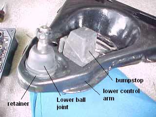
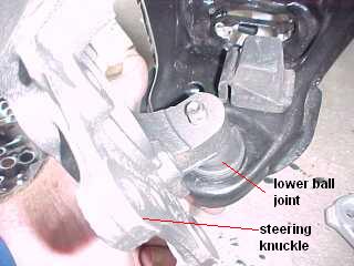
Here is a look at the lower control arm and the rubber bump stop. Since I cut the front springs to lower the car (1 Coil ) I cut 3/4" off the bumpstop to make sure I maintain suffecient travel. Also in the pic you can see the lower ball joint. I purchased them from Rodney Dickman, because it comes with a retainer clip to ensure they stay in and you do not have to tack weld them.
Install lower control arm with both nuts to the outside on each end with a flat washer behind the nut. NOTE: Do not fully tighten either upper or lower control arms at bushings until full weight of the car is placed on them, just snug for now.
[This message has been edited by Zoom88 (edited 09-06-2004).]
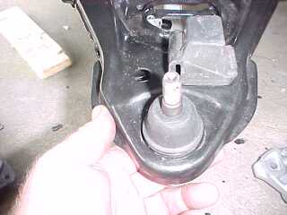
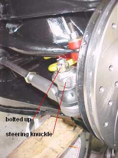
Now we are going to attach the steering knuckle to the lower control arm. Verify you have the correct knuckle for the side you are working on. (they are marked left and right)
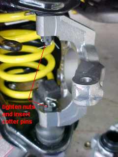
Here I do not tighten down yet. Just place the end of the ball joint through the knuckle and hand tighten the nut. Once I get the spring installed and the upper control arm ball joint connected to the knuckle and am satisfied everything is ok then I tighten it all up. Don't forget the cotter pins.
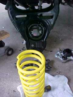
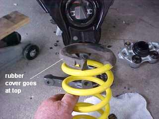
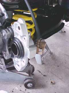
We are now ready to install the spring. NOTE: I do not use any spring compressors with the front springs. Still be VERY CAREFUL when installing front or rear springs !!
Since these springs are cut as mentioned previously (1 full coil) all info I have read suggests installing the cut end down or in the lower control arm. Install the rubber protective cover on the top end or upper control arm side. see pic below.
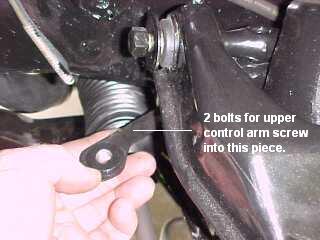
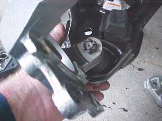
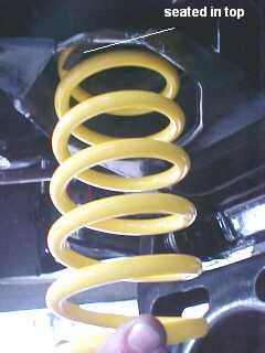
Its kind of hard to explain how to install the spring, but its not actually hard to do. But I'll give it a try. Place the upper end of the spring up into the housing that the upper control arm bolts to.
You will see a lip that should go up inside the center of the top coil spring. (sometimes helps to have 2 peoplewhile doing this) Now while holding the spring up in the upper housing lift the lower control arm up while at the same time trying to get the lower end of the spring correctly started in the lower control arm seat. It will not seat all the way until lower control arm is lifted . I place a floor jack under the cntrol arm at this point to help lift it up.
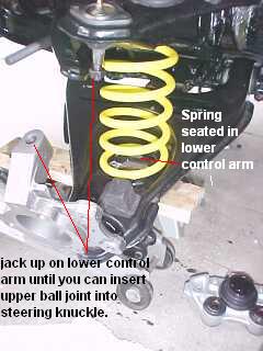
NOTE: On the lower control arm where the spring seats there is a little built in stop that the end of the bottom coil should rest against when installed properly.
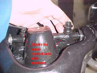
Now with everything in place just lift up on jack until you can connect the upper ball joint into the upper part of the steering knuckle.
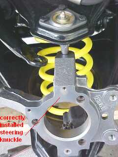
Once you have checked that the spring is seated correctly at both top and bottom and you are satisfied everything is installed correctly go ahead and tighten the nuts on both upper and lower ball joints and install the cotter pins.
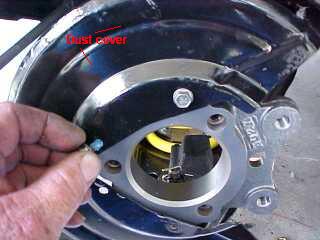
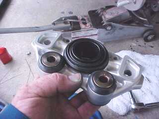
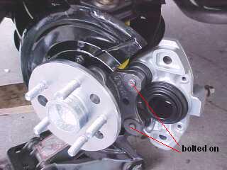
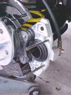
Now we can install the brake dust cover. Pay attention that you install it as shown. 2 things to keep in mind here. Opening in dust cover is where the brake caliper will install and if you where to take the cover off and flip it over and bolt it back on...well now your rotor will hit it and won't seat all the way back against the hub. Simple things but easily forgotten when in a hurry.
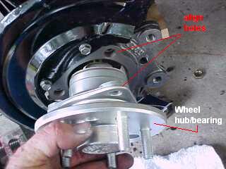
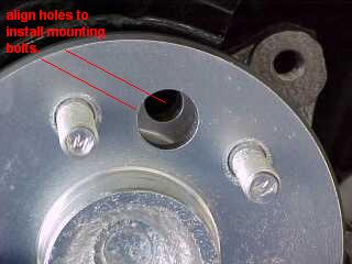
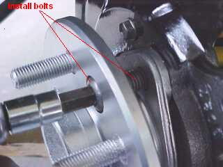
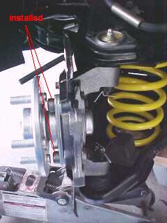
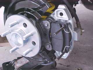
Ok lets install the front wheel hub/bearing. Slide it in as shown in pic below. You will notice that the hub itself has 3 holes in it. The larger hole is the one you use to install the 3 bolts. Rotate it around until it lines up with a hole in the steering knuckle, slip a bolt through the hole in the hub and screw it into the steering knuckle. Note: screw bolt all the way down until snug or when you go to turn the hub for the next bolt the head of the bolt you just installed will hit the back of the wheel studs.
Once all bolts are in tighten them up. Check out the pics below for more visual.
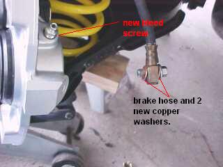
Now we can connect the brake line. I used 2 new copper washers and installed a new bleeder fitting. (If you want to use SS brake lines this would be a good time to install them)
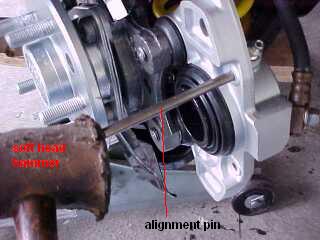
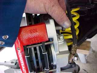
Install the 2 alignment pins (you can do this before installing the caliper if you like) just make sure you use a hammer with a soft head so as not to mushroom the ends of the pins making them hard to remove.
We already went over the rest of the brake install earlier above when I posted the rear brake install. So I will just post the pics .
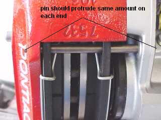
Pin should stick out about the same amount on both sides.
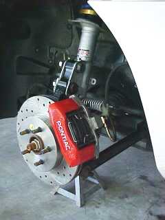
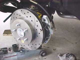
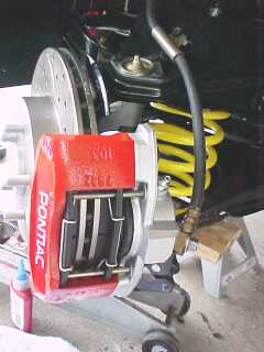
Brake complete
NOTE ** ROTOR IN PICS ABOVE IS INSTALLED ON THE WRONG SIDE OF THE CAR. THE CURVED GROOVES IN THE FACE OF THE ROTOR SHOULD BE GOING IN THE OPPOSITE DIRECTION. THERE ARE PICS LATER ON DOWN IN THIS POST THAT SHOWS THEM CORRECTLY INSTALLED.
[This message has been edited by Zoom88 (edited 09-10-2004).]
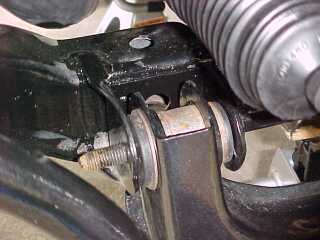
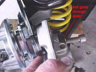
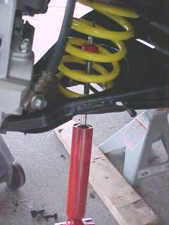
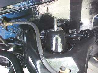
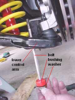
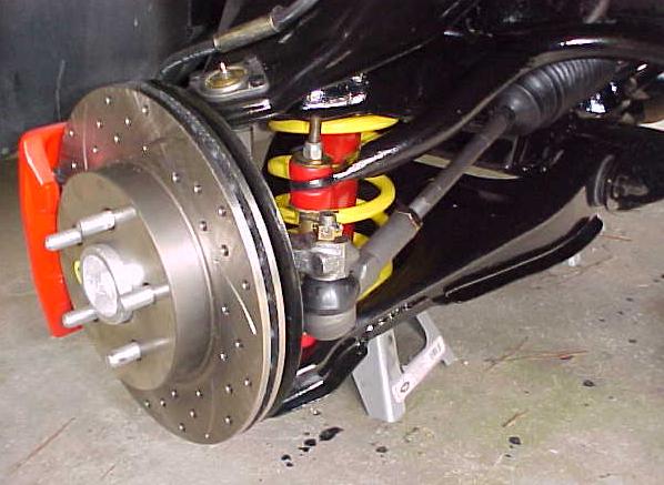
Installing the front shock. Place up through the lower control arm making sure you have the lower half washer and rubber or poly bushings installed on shock.
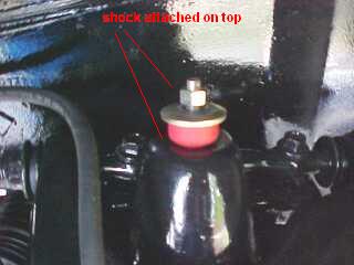
Threaded (top end) of shock goes up through hole as shown.
Top half of rubber or poly bushing , washer and nut installed
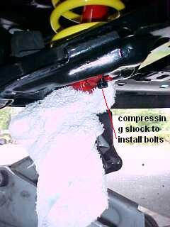
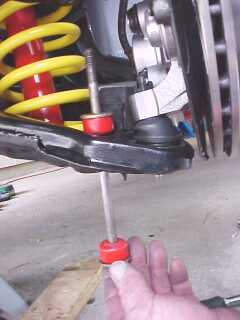
Using a floor jack on the bottom end of the shock to compress it just enough to get the bottom bolts in and started.
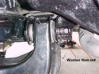
Start with it setup like in the pic below. Washer then rubber or poly bushing. Slide it through the hole in the lower control arm.
Now install the top half of the bushing along with another washer.
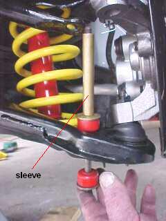
Now add the sleeve. I coat the bolt with grease just before installing the sleeve, makes it easier to remove next time.
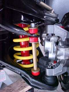
Put on another washer then bushing and slide the end of the bolt through the hole in end of sway bar. Add another bushing , washer and then a lock nut. Tighten until rubber or poly just starts to bulge. NOTE: never tighten so tight that rubber protrudes past the edges of the washers. This is way to tight and WILL cause premature failure !!
And last but not least. We install the outer tie rod end. (If just replacing you should have measured this distance by counting visible threads, marking with paint or measuring from a given point. This would allow you to set it up back close to what it was.) If not then I usually just check that the steering wheel is centered or straight. I then just adjust everything so that when I connect the outer tie rod end to the steering knuckle the rotor looks visually straight. It will definatly be going in for a front end alignment first chance I get !!!!!
Outer tie rod end connected to the steering knuckle, now once everything is pretty much adjusted best we can before alignment go ahead and tighten up the locknut for securing inner tierod to outer tierod.
NOTE ** ROTOR IN PICS ABOVE IS INSTALLED ON THE WRONG SIDE OF THE CAR. THE CURVED GROOVES IN THE FACE OF THE ROTOR SHOULD BE GOING IN THE OPPOSITE DIRECTION. THERE ARE PICS LATER ON DOWN IN THIS POST THAT SHOWS THEM CORRECTLY INSTALLED.
[This message has been edited by Zoom88 (edited 09-10-2004).]
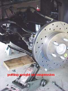
I now finish by jacking up the lower control arm until car lifted off the jack stand it was sitting on thus placing weight of car on the upper and lower control arms. Now I tighten the control arm bolt (the ones at the control arm bushings)
Grease everything up and take it in for a good alignment and thats pretty much it !!
NOTE ** ROTOR IN PICS ABOVE IS INSTALLED ON THE WRONG SIDE OF THE CAR. THE CURVED GROOVES IN THE FACE OF THE ROTOR SHOULD BE GOING IN THE OPPOSITE DIRECTION. THERE ARE PICS LATER ON DOWN IN THIS POST THAT SHOWS THEM CORRECTLY INSTALLED.
[This message has been edited by Zoom88 (edited 09-10-2004).]
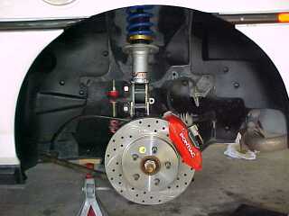
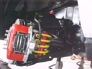
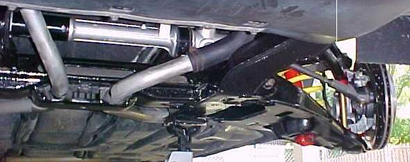
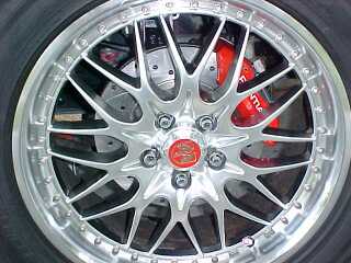
Some final pics....I hope some one gets some use out of this. It took alot of time stopping to take the pics, editting them and doing this write-up. It will depend on the response and feedback as to whether I will do this type of write-up again on any of the up coming future projects. Any way enjoy.
NOTE ** ROTOR IN PICS ABOVE IS INSTALLED ON THE WRONG SIDE OF THE CAR. THE CURVED GROOVES IN THE FACE OF THE ROTOR SHOULD BE GOING IN THE OPPOSITE DIRECTION. THERE ARE PICS LATER ON DOWN IN THIS POST THAT SHOWS THEM CORRECTLY INSTALLED.
[This message has been edited by Zoom88 (edited 09-10-2004).]