Okay, okay, so this might not be under the technical side of things, and it really should be in a kit car forum instead, but I thought the PFF group might like to follow this thread a bit, so I'll keep posting on this thread as long as I'm allowed.
Here's the deal. The Chrysler ME Four-Twelve. Brand new supercar, absolutely beautiful, and I'm never going to own a real one. So...I'll just do the next best thing and build one. Or at least that's the plan.
My goal is simple: Get as absolutely close to the real car as possible (outside and in) for as little money as I can dump into it (ie - using the university's equipment and supplies, etc, etc, etc. Don't worry folks, the art department at LA Tech already knows I'm working on this as an "art project" and stands behind it as my senior design project for my sculpting degree.)
So I've already started on the project and I thought I'd jump start this thing by posting a few pictures of where I'm at right now.
EDIT: Oh, and just to clarify things, I fully intend on this being a replacement body / body kit for my Fiero. Target date for full completion is September, 2004 for everything (interior, exterior, and Northstar installation which is in progress...again). Target date for completion of just the body is July 15, 2004.
Build date 3-16-04: Day 3
Starting off with a 1/5 scale plaster model of the ME Four-Twelve. To start, I simply gathered the measurements for the real car, and made a 1/5 scale wooden box to fit it. The box to pour the plaster in was 36" L x 16" W x 9" H. For anybody calculating the plaster, it took about 150 pounds, so about 20-25 gallons. (This thing was a beast to move since it's still wet. Probably weighed in at around 250 pounds.)
I let the plaster block dry down a little bit over night to make it easier for the chisel to grip into it and get a more predictable chiseling pattern. I drew some rough sketches on the block of plaster itself and just slowly knocked away the plaster until I got a rough shape and then used a (sharp) wood rasp to smooth things out, and a smaller (dull) wood rasp to really smooth out localized areas. To get it to a halfway presentable state, I sanded it down with 150 grit foam-backed sandpaper. (Paper sandpaper just soaks up the moisture too quickly at this point in the game and lasts the whole of about....5 minutes, maybe...?)
Anyway, here's where I'm at today. Lemme know what you think so far (and if you want me to continue this thread or not):
(On the one above, you can see where I made a boo-boo. Always follow your plans...
I'll post some more pictures as things progress. If anybody has any questions, feel free to ask.
Oh yeah, just in case people thing this thing will never work, you'd be surprised at how closely the body fits the Fiero's. Well, except for the 16.6" wheelbase extension, which I haven't quite worked out yet. Yeah.....
------------------ Patrick Horne
[This message has been edited by Patrick Horne (edited 03-16-2004).]
IP: Logged
08:08 PM
PFF
System Bot
TaurusThug Member
Posts: 4271 From: Simpsonville, SC Registered: Aug 2003
Could've used clay I guess, but the total time I've spent so far (something like 6 or 7 hours) to have gotten as far as I have, plaster was just the better route.
Oh, not to mention that clay has a really bad tendancy to shrink after it dries (like 11/13 it's original size) unless you spend a lot on really good plasticine clay or urethane clay, but the school's paying my costs, so... AND, clay wouldn't have worked well for transposing back onto the computer to do final tweaking. So I had my reasons for going plaster.
To fix the boo-boo: I only need half of the actual block (which I didn't realize until later), but it just gives me a little bit more room for error. If I need to work out some details on the door inlet, then i can do it on the boo-boo'd side instead of messing up the nice one. I'll cut the block in half when I'm done with it (to be covered later on) in order to scan it in 3D and duplicate the one "good" side.
If this is /too/ off topic for everybody, then let me know, and I'll just switch posts to the off topic section. But believe me, this process is going to get /very/ technical, thus its inclusion in this section.
------------------ Patrick Horne
[This message has been edited by Patrick Horne (edited 03-16-2004).]
IP: Logged
09:32 PM
rogergarrison Member
Posts: 49601 From: A Western Caribbean Island/ Columbus, Ohio Registered: Apr 99
Most of the people I know make the original mold off of a balsa wood or styrofoam model because its so easy to work. At least the rough one. Then you could make a cast of that to do the fine details. Looks like lots of work, but looks like it will come along. If you do make a full size, keep the molds and if you hook up with a fiberglass producer, make the kit. Some guys near here make plastic bodies of stock cars for GoKarts and they make a killing. Keep up the posts, I dont mind at all.
IP: Logged
09:34 PM
boristheblade Member
Posts: 501 From: Rochester, MN Registered: Nov 2003
Seems like quite a sweet project. Definetely not O/T, but so far more or less General. One thing im wondering about though, where and how are you going to achieve the 16" stretch?
IP: Logged
11:08 PM
crzyone Member
Posts: 3571 From: Alberta, Canada Registered: Dec 2000
Probably cheaper AND easier to do. I remember a thread or two where people had measurements off the car, too. Plus lots of pictures, and that bootleg video of it's buildup you can download. Plus anytime I've seen a thread on the car, someone always asks why somebody doesn't make a body kit of it.
Still, awesome job on that model so far!
IP: Logged
08:23 AM
Fie Ro Member
Posts: 3735 From: Soest, The Netherlands Registered: Sep 2001
I have been looking at pictures of the four-twelve too, nice car
I admire your plans and your work but your deadlines suck! Making the rebody is one thing, getting it mounted to the fiero chassis, with functional lights/doors etc is the biggest challenge... count in lots of extra time, you will need it to get everything right. Good luck. If you are very determent or a bit crazy there's no problem!
edit: move the rear wheel quite a bit front-wards ------------------ 1987 Pontiac Fiero GTR in progress 1969 Chevy Suburban
[This message has been edited by Fie Ro (edited 03-17-2004).]
IP: Logged
01:25 PM
Patrick Horne Member
Posts: 144 From: Ruston, LA, USA Registered: Nov 2001
Lol, unfortunatly I have no choice on the deadlines. I've got to have this thing done before I graduate, so I'm going to be on a tight schedule from here on out. Fortunately, I've got Mondays, Wednesdays, and Fridays (and weekends) to do nothing BUT work on this thing, so I'm hoping that the deadlines are semi-reasonable.
I did work some more on it today (about 9 hours worth) and got a good bit more done. The only section that I have left to do is the rear end and the top/glass.
Anybody who's looked at the real Four-twelve pictures: can anybody tell if there's sail windows on the sides (over the trunk area) or is that just an indentation? It's pretty hard to tell in the pictures that I'm working from. If it's glass, then that just means it's one more piece of glass that's going to have to be custom built. Fun...
I'll try to post some pictures once the rear end gets finished. Should be finished with the model by Friday, so I'll post some more pictures on Friday night of the completed model.
------------------ Patrick Horne
IP: Logged
11:35 PM
Mar 23rd, 2004
Patrick Horne Member
Posts: 144 From: Ruston, LA, USA Registered: Nov 2001
I finally got the plaster model done down to a point that I can now scan it and put it in 3D on the computer. Since I've got the original car's dimensions, I'm now able to easily plot out the car to a fairly close degree. This will in turn allow me to make a wooden fullscale jig that I'll be assembling the body on.
The plaster worked well, save for a few soft spots that didn't /quite/ make it past the powder stage. The pleasures of messing with plaster, especially this much of it. Like I said earlier, I only needed half of the body, because once it's in the computer, I can just mirror it.
Unfortunatly, this will be the last progress report until next week sometime. I had to order a special 141" blade for the bandsaw that I'm using, so I've got to wait until it comes in to post anything new. Hopefully, I'll have my better digital camera with me next time as well and therefore better pictures to post.
(Duplicated the side in Photoshop, just for fun, ya know.... )
Again, if anybody has any questions or comments, post away...
------------------ Patrick Horne
IP: Logged
02:46 AM
PFF
System Bot
RCR Member
Posts: 4451 From: Shelby Twp Mi Registered: Sep 2002
Great topic and good luck. The stretch is going to be a lonnnngggg one. Lambos typically go 11-12", so this one might need some work. Check out the chassis info at www.lambolounge.com for more stretch info.
Also, if you need reference material, I have a ton of links on building, constructing, designing, etc.
[This message has been edited by RCR (edited 03-23-2004).]
IP: Logged
08:06 AM
fieroman87 Member
Posts: 647 From: Lancaster, PA Registered: Nov 2003
fieroman87: What kinda kit did you have in mind? The only other car I can think of that'd fit (well, remotely at least) is the Mclaren body, which, if I remember correctly, needed a 17" stretch, but also quite a few more inches on the sides as well.
I'd actually LOVE to do a Koenigsegg CC, but I don't see that one happening, at least not with my pocketbook... I'll just have to keep on dreaming I guess.
------------------ Patrick Horne
IP: Logged
02:13 AM
rogergarrison Member
Posts: 49601 From: A Western Caribbean Island/ Columbus, Ohio Registered: Apr 99
That long of a stretch may be too long for manual trans shift cables. I dont know if any longer ones are available. You may have to make it an auto, which would be a good thing to me.... Looking good. Wouldnt it be cool if you could scan the body and use a CNC machine to cut out a finished body................. Maybe that could be done by making one on a full size block of styrofoam and just laying your glass on that........I dont know how big a limit CNC machines can be.
IP: Logged
07:11 AM
RCR Member
Posts: 4451 From: Shelby Twp Mi Registered: Sep 2002
Roger: I've seen pictures of a company that advertised they used a multi-axis cutter that would carve car bodies (or anything else) out of foam. I think it cost about 5-10K.
Patrick: I have a lot of links to different sites for body contruction. I've designed several Fiero based rebodies, one of which I want to build someday. I'll post here so others can use them too.
The first 4 or 5 sites are probably the most useful. Fibreglast.com has a wealth of info in the forums. Ari's site has a lot of good info on kit building. Check out some of the Lambo builds at Lambolounge for stretching the chassis. Lambolounge also has a real good links section.
IP: Logged
07:53 AM
Patrick Horne Member
Posts: 144 From: Ruston, LA, USA Registered: Nov 2001
RCR: Thanks a million! The Meerkat project car covers a lot of information that I've been wondering about but wasn't going to worry about until I got later on in the build. It gave me a lot of ideas though.
Roger: I too have looked at the whole CNC thing, mainly as a route for later selling the mold, but considering the cost, I don't know if there's anyway I could afford it. I think there's one in Shreveport, which isn't too far from here, so I might take my CAD drawing over to them just to see what they'd say. Still something that's up in the air.
Also, thanks for the feedback, guys. I definatly appreciate it!
(Side note: Now that I think about it, it's probably a good thing that I'm having to take a break from this until this weekend. I just realized today's date and that I've got two bronze sculptures due at the end of next week that have yet to be cast.... Hrmmm... ) ------------------ Patrick Horne
[This message has been edited by Patrick Horne (edited 03-24-2004).]
IP: Logged
12:46 PM
Mar 27th, 2004
Patrick Horne Member
Posts: 144 From: Ruston, LA, USA Registered: Nov 2001
Not going to be able to cut the plaster model up this weekend as I had planned. The guy that's letting me destroy his bandsaw isn't going to be in town like he thought he was going to be, so I'll have to wait another few days. (I hate delays... I really, really do. ) Oh well, no rush.
However, I did find an 87se fiero locally with a perfect black body, but no transmission/engine. He's selling it for $200 with a clean title and the auto transmission that was removed from the car. I'm not sure if I want to go ahead and get it, and use just the frame for this project (letting me /keep/ driving the N* fiero whenever it's finished in a month or so) or if I should hold off on it.
I'm worried that the 87 frame wont be the same as the 86 that it'll eventually end up on, or that the bodywork would be good on the 87, but completely off on the 86. Any suggestions?
Thanks
------------------ Patrick Horne
IP: Logged
01:51 AM
Fie Ro Member
Posts: 3735 From: Soest, The Netherlands Registered: Sep 2001
I'm worried that the 87 frame wont be the same as the 86 that it'll eventually end up on, or that the bodywork would be good on the 87, but completely off on the 86. Any suggestions?
If there are any differences at all between 86 and 87 frames they would be minor, I wouldn't worry about that...
RCR: some nice links there! Next time (IF!) I will start from scratch too
IP: Logged
07:43 AM
Apr 7th, 2004
Patrick Horne Member
Posts: 144 From: Ruston, LA, USA Registered: Nov 2001
Well, after almost two and a half weeks of waiting on somebody else, I've finally sliced up the plaster model into pieces that are small enough to scan.
I haven't scanned them yet since I've got some other stuff going on today and tonight that I'll need to take care of before I delve back into this thing, but I will take some shots of the completed slices before I scan them, just so everyone can get an idea of what I'm trying to do.
And irony strikes at the worst time. I found out that our 3D scanning computer (which has been down for the last month or so) apparently was fixed earlier last week when the service rep came and looked at it...AFTER I SLICED THE CAR UP! I hate it when crap like this happens...
Anyways, I'll post when I get a chance, but won't be able to work on the 3D modeling part of it until this weekend. Keep checking back.
------------------ Patrick Horne
IP: Logged
12:38 PM
Apr 11th, 2004
Patrick Horne Member
Posts: 144 From: Ruston, LA, USA Registered: Nov 2001
Okay, things didn't work out quite the way I had hoped with the plaster model. It causes a set back, but nothing /too/ serious.
Info on the cutting up process:
For those who are interested in doing something like this in another media first (like clay or plaster) for their model, here's what I did to cut up the car.
Figure out WHERE you want to cut. This is probably THE second most important step thus far (getting the dimensions of the car correct would be the 1st...which was my mistake to a degree). Since mine was a 1/5th scale, I cut it down the middle, so I'm only dealing with an 8" slab of plaster, which dramatically cuts the weight down for handling. I marked out 1" lines on the plaster itself and scribed them from the front to the back of the model. Leaves you with 8 individual sections, each with a pretty good bit of information on each. Number each section with a noticable mark (like 1F to 8F for slices one through eight of the Front half). This is important later on because this is going to be one big 3D puzzle, only there's no instruction book if you decide to stop the project for a little while. Document EVERYTHING.
I left the outer three sections as one piece. The reason for this was to cut up the outer 3" /towards/ what used to be the middle/interior of the car. (Assuming you're using the driver's side for the model, you'll be cutting vertically from the driver's side towards the passenger side of the car.) All those little details like where a wheel well starts and stops are good places to make cuts as it will be a good reference later on when you use the slices for the model. I cut this 3" layer into 6 pieces for the front and 5 pieces for the back.
Now, if you've got some details on the side as I did on the side air ducts, take ONLY the vertical sections with the most information on them and lay them down on their interior side and cut once again from the front of the car to the back of the car (working with the individual pieces, of course...) Only cut in areas that offer good refrence points: on mine I chose the top and bottom of the air duct as cutting points.
Once you've got this all cut up. Go back and make /sure/ that everything is documented really well. I can't stress this enough!
(cont'd)
------------------ Patrick Horne
IP: Logged
10:07 PM
PFF
System Bot
Patrick Horne Member
Posts: 144 From: Ruston, LA, USA Registered: Nov 2001
My mistake largely lied in the problem that the pieces I cut were too large for the scanner, so getting any kind of an accurate scan is kinda tough, so many of my proportions were off after the scan. (I would've re cut the pieces, but if you've ever ran plaster through a bandsaw blade, you'll know it tends to dull and get rusty almost over night, and it's been sitting over the weekend sooo.....)
Take the pieces and lay them on the scanner (flatbed scanner is what I used) but only do one section at a time. Scan the image and save it as a name that'll give you a pretty good idea as to what part it is you actually scanned (hrmm, could this mean documenting things again?? I do believe so...! :dizzy ). The large flat pieces from the interior are the easiest and should be done first.
The outer pieces are a bit more difficult. Okay, a lot more difficult...
The outer pieces need to be scanned one side at a time, but it actually will work out better for you if you scan one side span with its individual pieces in one scan rather than two or three scans for /each/ individual piece. The trick to this part is that you're basically doing /at LEAST/ two scans per vertical span and at /least/ three scans for the vertical spans that are cut again horizontally. (Go ahead, read all that again, because it probably didn't make sense the first time through... )
Start in the front and work your way to the back. Another good hint would be to lay out the outer pieces on the span closest to it in the same way as it was on the model, and mark where the blade made a space on the interior span, that way you'll have a refrence point when you work with it in 3D.
I'll post some pictures on the next post to clear things up a bit.
(cont'd)
------------------ Patrick Horne
IP: Logged
11:07 PM
Patrick Horne Member
Posts: 144 From: Ruston, LA, USA Registered: Nov 2001
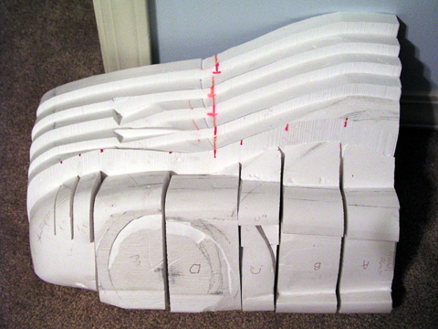
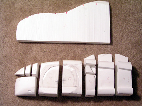
Okay, now for those that think more visually than verbally: the pictures to explain what in the heck I'm talking about!
Okay, here's two shots of the model after it got cut up into the interior pieces (cut from front to back) and the exterior pieces (cut vertically towards the inside of the car):
A layed out section showing the exterior pieces and the closest interior span:
The front two spans:
Set up for the vertical interior scan of the front two spans:
Scan for the horizontal interior scan of the front span:
As always if anybody has any questions about any of this, please feel free to shoot me an email at phorne_tca@yahoo.com I'll try to help you out as much as possible.
------------------ Patrick Horne
IP: Logged
11:17 PM
Patrick Horne Member
Posts: 144 From: Ruston, LA, USA Registered: Nov 2001
As I said earlier, I screwed up somehow on the model (I think). The next step in this process is importing the scanned images into a 3D graphics program. I'm using Maya and then plan to export it to Autocad to make the final slices and get the numbers correct. You could use just about any program that'll let you import images on a per-plane basis, like 3D Studio Max or Blender or whatever. It just happened that I have access to Maya on the school computers, so that's what I'm going with.
This part is fairly easy but very time consuming. Just import the images you scanned earlier on the plane that you'll be actually moving them around on. If it's a scan of the side pieces, load the image on the 'side' plane, trace them with either a NURBs curve if you want to work in NURBs or in polygons, which is the way I went simply because it's faster and I'm already behind schedule.
Once you get everything traced, just add surfaces to the spans, and add in details. Easy to say, tough to do. This takes a lot of time, folks. Don't think you're going to bust through this part in a few hours (unless you're just REALLY good). Keep in mind that the final slices for the actual wood jig to go on the car itself are going to be taken from this 3D model, so be as accurate as you can afford to be!
Now for my own progress report: My slices wouldn't scan in correctly for some reason. I know the method above works because I've done it before on an earlier model, and I was taught this by somebody who did this for a living a few years back, so the method DOES work. It just won't work when you're pushing the limits on scheduling.
So I've had to restart from scratch. Well, kinda. I'm just using the pieces that did work from the scans, and building an entirely new model in 3D. This sounds like it's bad and going to be a set back, but it's really not. The ME Four-Twelve is a fairly easy car as far as modelling, since it's got a lot of straight lines and easy angles. Most new cars do (a hint if you're going to come up with you're own new concept car).
So I'll probably be done with the modelling by sometime this week. I'm about halfway through and I've spent maybe 7-8 hours in the 3D program, so I'm not too bad off. I'll post pictures later when I've got it done. Unfortunatly, I've got some stuff in an art show this week and I'm still trying to get the old iron duke back in my '86 so I can get the '88 on the jack stands instead. We'll see what happens!
------------------ Patrick Horne
IP: Logged
11:53 PM
Apr 24th, 2004
Patrick Horne Member
Posts: 144 From: Ruston, LA, USA Registered: Nov 2001
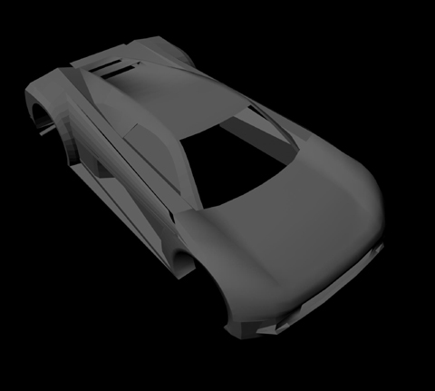
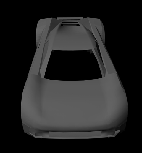
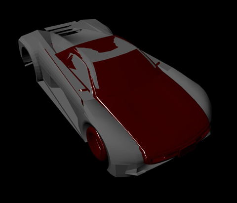
Okay, it's been a couple of weeks and I have to say that I haven't done a whole lot with the car. I've modelled it out some on the computer but it's been kind of a busy couple of weeks, so I'll just post what I've got so far.
This next one is kind of a neat image to me. It shows just how closely the original has been followed.
As you can see, the back hasn't been worked on much yet. Same goes for the front
Anyway, that's what I've got. A lot of the modelling did end up coming from the plaster model, so all was not lost. The scanned model just had to be shifted and scaled around a little bit to get it to match up correctly.
As always comments and questions are welcomed.
------------------ Patrick Horne
IP: Logged
06:05 PM
Patrick Horne Member
Posts: 144 From: Ruston, LA, USA Registered: Nov 2001
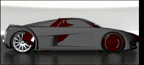
Just thought I'd post these images too. These are two pictures with the Fiero (in Red, duh) underneath the body and scaled to it's correct size with the Chrysler body on top of it. Check out how closely it fits...
------------------ Patrick Horne
IP: Logged
06:18 PM
longjonsilver Member
Posts: 1113 From: Lower Sackville, Nova Scotia Registered: Nov 2001
Just thought I'd post these images too. These are two pictures with the Fiero (in Red, duh) underneath the body and scaled to it's correct size with the Chrysler body on top of it. Check out how closely it fits...
Ouch Well I think it might look better shorter!
IP: Logged
07:22 PM
Apr 25th, 2004
Patrick Horne Member
Posts: 144 From: Ruston, LA, USA Registered: Nov 2001
I keep thinking the same thing about it being shorter. That 16" stretch is going to kill me I think. I'm still working on going as close to the real thing as possible though. It's proving tough, since I don't really have any reliable measurements other than length, width, and height.
I started thinking a few days ago about the C5 vettes and just how big they are. Ironically, the Four-Twelve's wheelbase and the vette's wheel base are pretty close. I just wouldn't want to get a C5 vette only to cut it up.
Wow, the comparison with the Fiero and the Body you are working on is real close, and makes the project seem even more possible. Could the lines be screaming for a longetudinal swap? The front fascia really isn't a problem to make match on the lines. The front hood might be a problem. The roof and windshield lines could be fixed by using some chop top procedures to make the lines match. You are doing great. Even if the car body doesn't make deadline, you have a very unique 3-D puzzle you can build.....LOL. Great post, you have done a lot of work. You have a great start on making your deadline, but I have to admit it is an ambitiuos goal. My hat is off to you on your success, so far. Jim
IP: Logged
09:29 AM
PFF
System Bot
Flyguyeddy Member
Posts: 568 From: pekin, Il USA Registered: Dec 2003
Thanks for the positive feedback, everybody! I was starting to get worried that interest from others had more or less slacked off, but it's nice to know that people are actually /interested/ in this whole ordeal.
Slater_334: As I said earlier in the thing, this is being considered a senior design project, so the school is paying for the basic materials (namely stuff that we already keep in stock, like plaster, plywood, steel, aluminum & bronze casting materials, and various tools). The fiberglass materials are coming out of my own pocket, but I'm getting them for next to nothing from one of my friends who uses a lot of fiberglass in building custom speaker boxes.
The biggest expense in the project (I hope) will be the front windshield and the tires/rims, which I can't seem to find anywhere. The glass is one continuous stream from front to back, built in three pieces. This part's not going to be an issue because the pieces are small enough to just slump in the kiln at Tech. The windshield, I'm a little leary about, and I don't know how to go about getting a custom windshield made.
As a sidenote, I'm thinking that the longitudinal mount is going to be the best for it, especially as far as the frame goes. I'm trying to find out as much as I can about the Northstar and Audi 5000 transmission (or whatever it is that's in the 1984 Audi Coupes...) I'm thinking that's going to be the cheapest route, instead of having to buy a Porsche 928 transmission... )
I would just leave the front windshield and the roof alone. Just use fiberglass to cover up parts of the windshield and build up other parts to give an illusion. In the end, cheaper and eaiser for you. And if you are considering making this a kit car, cheaper and easier for people who do buy the kit.
IP: Logged
03:35 PM
RCR Member
Posts: 4451 From: Shelby Twp Mi Registered: Sep 2002
Keep going Patrick. You've got a long road ahead of you, and a short deadline. I did all my designs in Rhino3D, so I know where you're going. Good luck, we're all with you.
later... Bob
IP: Logged
07:29 PM
boristheblade Member
Posts: 501 From: Rochester, MN Registered: Nov 2003
You really need to start thinking about the engine as well. After all, with all thos elooks, that car is going to need some serious horsepower to back it all up. A BMW V-12 witha set of twin turbo's sounds about right
IP: Logged
08:17 PM
rogergarrison Member
Posts: 49601 From: A Western Caribbean Island/ Columbus, Ohio Registered: Apr 99
A totalled C5 may not be all that bad to buy. Not that big a deal to make a 2 rail box/tube frame and use all the vettes suspension parts, drivetrain and electronics. Also gives you a 350 engine and transmission. Remember on those the engine is in front and the trannys in the rear. So you might have enough room to put them both behind the cockpit and use a very short driveshaft between them. Im not exactly sure of the drivetrain layout without some drawings in front of me. Keep it up. Id thought several times about making a one off Vector 'like' body kit. Its all simple, angular lines in a general wedge shape. I was going to use a foam cored fiberglass premade panel made for RVs and cut it all up into the parts and bond them together. We used to buy them from Winnabago 8' high and 25' long for repairing damaged.motor homes.
IP: Logged
09:03 PM
Patrick Horne Member
Posts: 144 From: Ruston, LA, USA Registered: Nov 2001
boristheblade: How about a hopped up northstar? It won't be able to make it in by my September deadline, but it'll eventually be in there. It'll have the power to back up the looks, believe me. Ever notice that almost all 'ricers' are nice and shiny on the outside with their new little body kits, but usually have no Umph to back up their new-found good looks? Yeah. That always ticks me off, so it's not going to be the case here.
RCR: Looked at your site, and I've gotta say, those are pretty nice designs! You should definantly follow through with those (especially that first red one, IMO ) Thanks for the encouragement, too!
I've hit a slight bump in the road, but nothing that will put me too bad off course. I found out today that our department doesn't have the money to fund classes in the building that I'm usually working in, which has all the fun little toys like the welding machines and plasma cutters. (And who would've guessed they'd not have money after deciding to fund projects like THIS one...?? ) Anyway, it'll just force me to get everything worked out on the top and rear windshields, before fall, so I might have to push my deadline back a couple of weeks so I can get the glass slumped and installed. Also kinda puts a crimp in the headlight/tail lights building. I don't know how I'm going to work around not having an oven big enough to cook plexiglass in...
I'll keep you all posted
------------------ Patrick Horne
IP: Logged
11:44 PM
Apr 27th, 2004
Patrick Horne Member
Posts: 144 From: Ruston, LA, USA Registered: Nov 2001
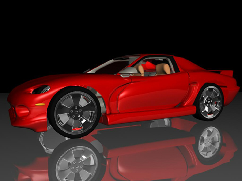
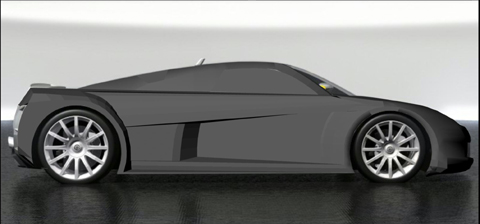
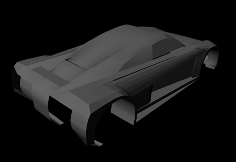
This is pretty much off topic, but since these aren't posted anywhere and RCR got me thinking about some of my older projects, I figured I'd post these images from the last one that I started working on. I quit, because it looked too much like a Viper, and too much like, well, crap.
Anyways, it'll at least give you all an idea of where I'm heading with this project. I'm not very good at skipping little details. Hopefully the ME Four-Twelve is going to look somewhat like this once it gets done, only, not like crap.
Side View, looking like a gimpy Viper and in red:
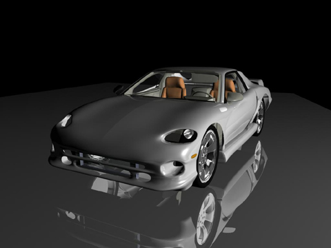
Front Quarter View, looks better, but mostly due to the silver color:
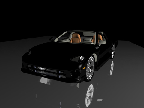
Same View, but in black, cause black's just cool.
Anyway, just thought I'd give you something to look over, RCR. You should seriously consider building the car /YOU/ like!


_Elevated_Rear_View_1.jpg)
_Elevated_Side_View_1.jpg)
_Front_Quarter_View.jpg)
_Level_Side_View.jpg)
_Rear_Quarter_View.jpg)

_Vertical_Frontal_View_2.jpg)


 How are you going to fix the boo-boo?


 Making the rebody is one thing, getting it mounted to the fiero chassis, with functional lights/doors etc is the biggest challenge... count in lots of extra time, you will need it to get everything right.
 Fun...
_Elevated_Front_Quarter_View.jpg)
_Elevated_Rear_Center_View.jpg)
 )
)_Front_Quarter_View_1.jpg)
_Level_Side_View_1.jpg)
_Rear_Quarter_View_1.jpg)
_Rear_View.jpg)


 )
) ) Oh well, no rush.
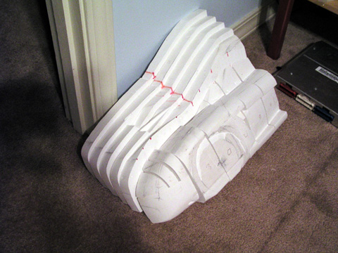
.JPG)
.JPG)
.JPG)
 Well I think it might look better shorter!