 
     |
| AC R134 Conversion (Page 2/8) |

|
fierosound
|
JUL 17, 01:13 PM
|
|
Very detailed information in link posted earlier...
| quote | Originally posted by Spadesluck:
Here is a good link to get you started. R134 Conversion |
|
[This message has been edited by fierosound (edited 07-17-2018).]
|
|
|
|
RWDPLZ
|
JUL 17, 01:17 PM
|
|
| quote | Originally posted by fierofool:
The project I'm in the sidelines on had problems getting the pressure switches out of the old compressor and broke them. They had to purchase the new 2 wire style switches. We're assuming that these are simply pass-through switches with either wire being grounded to the engine. Is this correct? If not, how are they wired into a single wire system?
|
|
Yes, the originals ground through the compressor body. Most people hook the two new wires to a ring terminal and use one of the compressor mounting bolts as a ground on the compressor.
| quote | Originally posted by fierofool:
Does it matter which port the switch is installed in? I understand that they must be connected to the proper harness, but aren't the two switches sensing a common chamber in the compressor?
|
|
They can go in either hole, same chamber in the compressor.
If you look closely at the inner ring here, you can see two holes drilled into the casting. These go to the other side, where the pressure switches are.


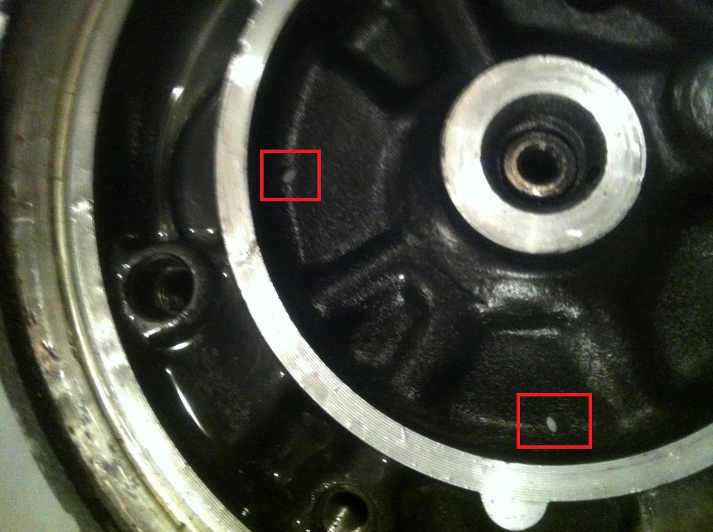
http://www.fiero.nl/forum/Forum2/HTML/124630.html
|
|
|
|
fierofool
|
JUL 17, 01:26 PM
|
|
|
Both wires on both new switches are white. Does it matter which of each goes to ground?
|
|
|
|
RWDPLZ
|
JUL 17, 01:57 PM
|
|
|
Nope, they're just literally normally closed switches.
|
|
|
|
computer_engineer
|
JUL 17, 05:58 PM
|
|
| quote | Originally posted by RWDPLZ:
The red one is the high pressure cut-off. You can test both by checking for continuity between the center tip and the metal outer shell (should see continuity, not open)
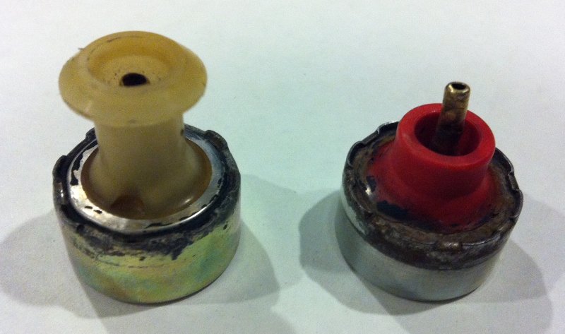
The ones here should be replaced, they're not in good shape. |
|
Do you have any photos of the switches mounted into the compressor? So I can have some idea how they are supposed to come out.
Thanks!
|
|
|
|
RWDPLZ
|
JUL 17, 06:05 PM
|
|
They're held in with snap rings, you need snap ring pliers to remove them. There are then o-rings in the recessed area that seal them in.
Here are a couple dirty/broken ones from cam-a-lot's car

|
|
|
|
computer_engineer
|
JUL 18, 04:23 PM
|
|
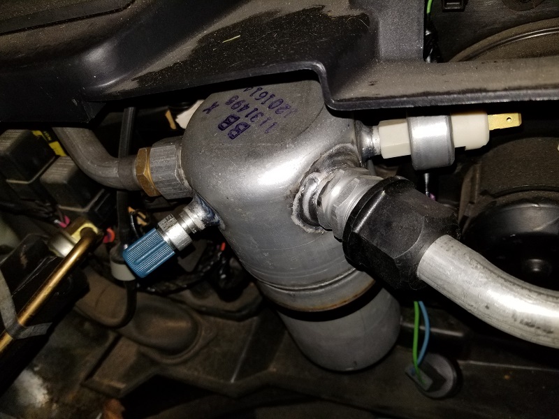
Is the clutch cycling switch the thing that is sticking out of the side of the accumulator? I have to assume that it is, since the refrigerant lines and low side service port take up the other connections.
 [This message has been edited by computer_engineer (edited 07-18-2018).]
|
|
|
|
RWDPLZ
|
JUL 18, 04:32 PM
|
|
| quote | Originally posted by computer_engineer:
Is the clutch cycling switch the thing that is sticking out of the side of the accumulator? I have to assume that it is, since the refrigerant lines and low side service port take up the other connections. |
|
Yes. It should kick off at 25psi for R-12, and 21psi for R-134, there's an adjustment screw between the terminals, or you can buy one pre-adjusted.
|
|
|
|
RWDPLZ
|
JUL 18, 05:47 PM
|
|
I circled it in your pic
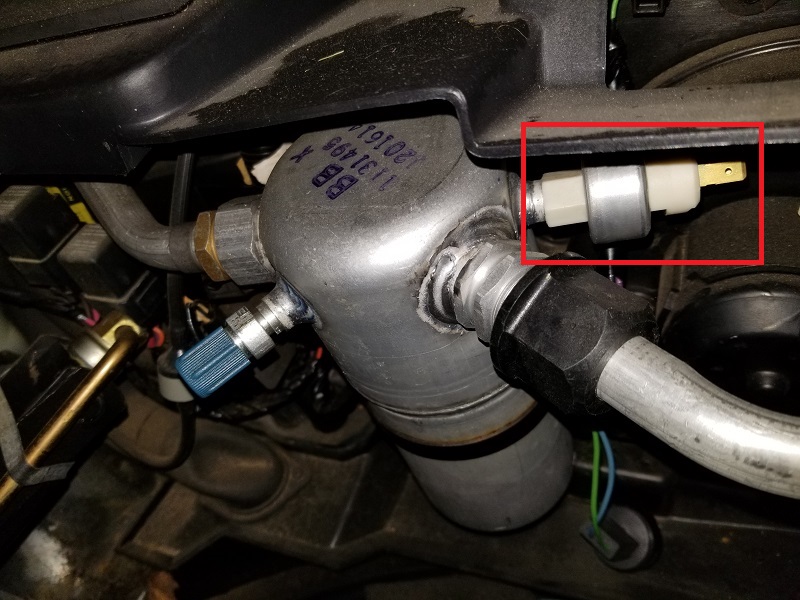
That thing hanging down with the blue and green wires is the electrical connector for it.
|
|
|
|
computer_engineer
|
JUL 19, 01:48 PM
|
|
| quote | Originally posted by RWDPLZ:
I circled it in your pic
That thing hanging down with the blue and green wires is the electrical connector for it. |
|
Yeah - I had disconnected it looking around it for what needed to be done to remove the accumulator. Just hadn't reconnected it before taking the picture. 
|
|
|
