Glad you'll keep following along Seajai. Looking forward to your continued input. I remember the paper and pencil days as well. Its amazing how far drafting has come, but there is nothing like a good hand drawn sketch to get an idea off the ground.
Glad you'll keep following along Seajai. Looking forward to your continued input. I remember the paper and pencil days as well. Its amazing how far drafting has come, but there is nothing like a good hand drawn sketch to get an idea off the ground.
And ERASING!!! and erasing and erasing.... (The TRUE value of autocad LOL)
Thanks Fieroguru. I agree that having that structure hanging out there is certainly a point of concern. Perhaps something like this would help. Just run a tap right through the spindle casting and fit a longer bearing bolt with a nut on the end to help support the toe bracket. The back side of the casting is quite flat so it might be a good place to mount the extra gusset.
Yes, something like that. I was thinking about it being on the other side of the upright and bearing mounting flange, but the backside works too!
Yes, tonnes of erasing 85-308. I remember when we got an electric eraser. It was so high tech at the time. I still have it in my drafting table drawer..... as a conversation piece..... along with all the other manual drafting tools of the trade. Look at that plug..... and an all metal casing........that can't possibly meet code today ha-ha-ha
I figured you were thinking about the other side Fieroguru by the image you quoted. As I was drawing it though, it just seemed more natural to stay on the back side of the spindle.
On the topic of outdated yet useful tools, anyone care to guess what this is called or used for? You can scale from the sheet of paper it is sitting on for the approximate size. Hint....... It is made from good old fashion lead btw.
Hint : I am sure they were used by automotive designers years ago as well.
I just tried the eraser again... after probably 25 years... and it still works. I forgot that the eraser spins as opposed to vibrates back and forth like you would expect. And it's incredibly quiet still. Quality made in Dallas Texas.
[This message has been edited by Yarmouth Fiero (edited 02-02-2015).]
On the topic of outdated yet useful tools, anyone care to guess what this is called or used for? You can scale from the sheet of paper it is sitting on for the approximate size. Hint....... It is made from good old fashion lead btw.
Looks pretty heavy.. was it used to hold multiple sheets of dwg paper or onionskin 'in register'? Pretty sure it isn't an extra-marital device.. (ok, everyone say 'ewwwww' ...)
What the heck? That electric eraser looks like it's made for some serious mistakes, LOL. The precursor to a shredder. What's it got... a 5 amp motor? At military college all we ever got was eraser bags... a little cloth bag filled with vinyl eraser powder that you rubbed over your drawings to erase hand and finger smudges.
As for that other thing? My guess is it's one half of a spot welder that you've mistaken for a drafting tool... well, either that or a cure for hemorrhoids.
... At military college all we ever got was eraser bags... a little cloth bag filled with vinyl eraser powder that you rubbed over your drawings to erase hand and finger smudges.
yeah! and we had to WALK to school. In the snow! Uphill. BOTH ways... ahhh, the GOOD ole days.....
I must have been important... I got an eraser that was battery powered! Well, ok, I got about twelve.. kept wearing them out.... No more guesses on that ... thing....
ha-ha-ha-ha. I love this chatter ha-ha-ha. Ya, that is a serious eraser for some serious mistakes. Not so long ago, we would loft ( draw ) a vessels lines plan ( 3 views ) full size on the loft floor which was painted white. From that, we could make full size templates for the longitudinal and transverse frames of the vessel. The lines were often drawn several times so there was alot of lines to erase and redraw. We'd plot vessels up to 65 ft in this manner. Now of course its all done on the computer and the parts are cut using a large cutting table using a plasma cutter or laser. Before these, it was all oxy-acetylene cutting heads. At the time, lofting was considered a high tech skill because before that, ship builders only used a scaled half model of the hull to build a full size vessel.
So the odd item I posted above was often used for the lofting exercise. Using a long plastic spline ( strip of plastic with a groove down one edge) the 'spline weights' or ducks as they were commonly called would be positioned alone the spline to hold the shape so the draft-person could trace the shape on to paper or a loft floor. It was a very slow and tedious process but allowed you to develope a keen eye for a fair line. I am sure that automotive and even aviation designers used a similar set of tools.
Looking back, I am sure making the weights from lead meant that they didn't leave rust stains on the paper..... but the lead on our hands is probably why most boat builders went mad...mad I say....
On the topic of outdated yet useful tools, anyone care to guess what this is called or used for? You can scale from the sheet of paper it is sitting on for the approximate size. Hint....... It is made from good old fashion lead btw.
Spline weights! I studied yacht design...I have a set myself. Anyone have a planimeter kicking around?
You got it Neils88. I think there are still enough bits and pieces of a planimeter in the back of the drawer but I never had the patients to use one accurately.
I would maybe suggest getting 88 rear knuckles and emulating the 88 rear suspension, Blooz should have all the suspension pivot locations in his CAD drawings.
This would have benefits such as utilizing the stock 88 calipers with ebrake and using 12 or 13" brake rotors, and improved suspension design.
If you stick with the stock 84-87 knuckles then you are forced to use stock size solid rear rotors if you want a parking brake, and you still have a backwards front end suspension on the back of your 355 Ferrari....
Food for thought!
I think you could easily get it done
If it were myself I would make the lateral links the same length and parallel to have no rear toe movement, and then you just need to decide antisquat % based off ride height trailing arm angle and length. I think it would be easier in the end than the current plan, and less unsprung weight.
[This message has been edited by zkhennings (edited 02-03-2015).]
There are lots of rear brake options aside from the stock fiero ones; what ARE your plans for rear brakes? A possibility is the 05 Chev Uplander rear caliper; c/w built-in e brake; made to stop a much heavier vehicle.... very readily available. An adapter would be needed but that would be the case for any non-stock caliper.... I was toying with the idea of replicating the 88 rear myself, but the main issue is reducing or eliminating that annoying bumpsteer, and you are working at that... so it won't really matter which way you go now, I think.
i have some of the uplander calipers if you need any size info. They are available all over for $25 at wreckers; for cores or measuring etc. GP
those spot calipers are acceptable? I don't know; just asking. Last time I checked here, in ON, they weren't. Maybe they just didn't have a certain certification then, I have no idea. Decided to go with some OEM type that won't get an argument, at least to get thru the safety check....
Even if they weren't, I think it would be pretty easy to adapt a small hydraulic caliper such as one from a motorcycle or ATV. The small master cylinder could be attached to a push rod on the parking brake handle. You'd need to find a caliper that was of a split design so you could adapt the thickness to your rotor.
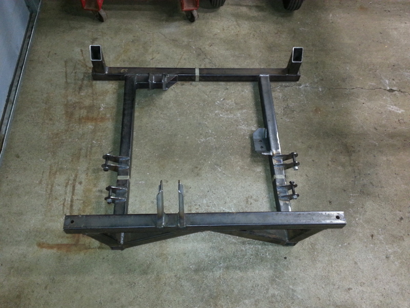
Well today I finally got my new aluminum engine cradle welded together. The main rails are 3" x 4" x 1/4" HSS and tapered down to 2" x 4" x 1/4" at the forward bushings. The transverse members are 2" x 3" x 3/16" HSS and are only tacked in place to hold everything together. Their final location will be determined by the requirements of the engine / gearbox mounts and it will be a while before I get to that stage. The rear cradle supports still need to be drilled to accept the poly bushings. The lugs for the control arms are only sitting in place for the photos. Again, their exact location will be determined once the new control arms are finished. They have been drilled oversize to accept SS inserts which have not been pressed in yet. This will prevent the control arm bolts from wearing the holes in the aluminum lugs. The control arm bushings have been fabricated from 2" sch 80 seamless SS pipe. I designed the bushings to be slightly longer than stock to suit the increased dimensions on the control arm structure. I bought two sets of poly bushings and cut them shorter so that I could install two bushings, one from each side. I had new bushing inner sleaves machined to suit the new total poly bushing length.
I haven't weighed the new cradle yet but will try to get that done so I can compare it to the weight of the stock cradle.
I appologize for the poor quality of the photos. My email is down so I had to text them to myself.
[This message has been edited by Yarmouth Fiero (edited 02-21-2015).]
Nice to see people doing / fabricating nice stuff for these types of cars. It seem like there is no end in what imagination can do with a project car. The fiero seems to be the only popular platform that can be done with many body kits, suspension upgrades, and engine swaps, and so on.
I have no plan on doing custom work besides maybe an engine swap in the future, but I guess I will leave Blooze and yourself to do re-engineering fiero projects here in the maritimes.
Thanks fierogt28. It's certainly alot of fun to be able to design a modification and then build it. But you are right when you say " It seems like there is no end ......" It was only a few pages back I was documenting the process of stretching my stock cradle. Now I have taken it in a completely different direction.
There are many interesting builds on this site and all the builders offer their unique variation regarding concept and execution. It's very interesting to watch them all develop.
My next step will be to fabricate my rear control arms and then weld up the last of the structure in my engine bay. Then I may even be able to set the rear of the chassis back on its own wheels. Its been a long-g-g-g-g time since that last happened.
I weighed my stock cradle at 48 lbs and my new aluminum cradle at 44 lbs. As a side note, my stock cradle had a 3" stretch so the weight may seem slightly higher than others have recorded.
Great job on the cradle! I too made my own, however it comes in at a whopping 66 pounds. Perhaps I should now make one in aluminum. Decisions, decisions.
Well today I finally got my new aluminum engine cradle welded together. The main rails are 3" x 4" x 1/4" HSS and tapered down to 2" x 4" x 1/4" at the forward bushings. The transverse members are 2" x 3" x 3/16" HSS and are only tacked in place to hold everything together. Their final location will be determined by the requirements of the engine / gearbox mounts and it will be a while before I get to that stage. The rear cradle supports still need to be drilled to accept the poly bushings. The lugs for the control arms are only sitting in place for the photos. Again, their exact location will be determined once the new control arms are finished. They have been drilled oversize to accept SS inserts which have not been pressed in yet. This will prevent the control arm bolts from wearing the holes in the aluminum lugs. The control arm bushings have been fabricated from 2" sch 80 seamless SS pipe. I designed the bushings to be slightly longer than stock to suit the increased dimensions on the control arm structure. I bought two sets of poly bushings and cut them shorter so that I could install two bushings, one from each side. I had new bushing inner sleaves machined to suit the new total poly bushing length.
I haven't weighed the new cradle yet but will try to get that done so I can compare it to the weight of the stock cradle.
I appologize for the poor quality of the photos. My email is down so I had to text them to myself.
WOW, I realy like what you have done. I wish I had this for my LS4 swap. I have a GM aluminum cradle, and did (at the time) compare it to a stock Fiero cradle and the difference was a lot in %. But after the LS4 Fiero cradle, the aluminum advantage was even better.
Thanks Lunatic. Nice strong cradle you fabricated. I suspect mine will get heavier once I start adding engine supports and some cross bracing. Its bare bones at the moment but will allow me to install my control arms and set up the rear suspension.
Thanks as well Rickady88GT, I am hopeful the cradle will be a suitable compliment to my eventual LS1 or SBC... or whatever I end up with
In this instance, I use the term HSS in reference to Hollow Structural Section. While the term usually refers to steel sections in the construction industry, we also use it for aluminum hollow sections in the marine industry, whether they be square, rectangular, circular or oval in section produced by extrusion, rolling or formed and welded . They are considered structure shapes as opposed to pipes or tubing which are designed to carry fluids and gasses.
Thanks for asking. I know I should be more clear when using acronyms.
Edit to add: with regard to the aluminum material used, all HSS is 6061-T6 and all plate is 5083 / 5086 H116.
[This message has been edited by Yarmouth Fiero (edited 03-04-2015).]
Thanks for the edification of terminology. Very informative. Sorry for the late reply, been awhile since I've been on PFF.
Ken
quote
Originally posted by Yarmouth Fiero:
Hi Ken
In this instance, I use the term HSS in reference to Hollow Structural Section. While the term usually refers to steel sections in the construction industry, we also use it for aluminum hollow sections in the marine industry, whether they be square, rectangular, circular or oval in section produced by extrusion, rolling or formed and welded . They are considered structure shapes as opposed to pipes or tubing which are designed to carry fluids and gasses.
Thanks for asking. I know I should be more clear when using acronyms.
Edit to add: with regard to the aluminum material used, all HSS is 6061-T6 and all plate is 5083 / 5086 H116.
Thanks guys. My plans for the cradle finish fierogt28 is to powdercoat either black or gold nugget like the roll bars. That won't happen until I have an engine ready to mount.
No problem kennn. I only get on here a couple times a month myself now.
Spent the weekend mocking up the driver side control arm. Still need the ends cut to length and then prep'd for welding. The bushings are laying to the left. The tubing is all steel, seamless 1 1/4" and 1" with a 0.120" wall thickness. The bushings are 316 stainless steel seamless sch 40 pipe.
Looking very nice! Looks like two good, tight-radius bends on the piece on the right side; what do you have for a bender? What thickness are you making your balljoint mounting plate. This looks very substantially heavier than the stock piece!
What was your final 'overlength' ie how much longer did you have to make the control arms? GP
Thanks. The tubing was bent on our hydraulic tubing bender. Its a sweet machine. Just type in the angle and press go. We do a lot of hydraulic tubing at our shipyard. The die radius is 2 x tube dia. so 2 1/2" radius for the 1 1/4" tubing.
The plate for the ball joint is 3/16". Its thicker than stock but once you cut the 1 5/8" hole for the ball joint, there won't be much material left and I didn't want the control arm tubing wrapping all the way around the plate due to clearance issues with the spindle and the brake rotor.
Edit to add: The control arm length from bushing to ball joint axis is 13 3/4". Off the top of my head, I don't recall what the stock length is but its got to be close to 12". I tried to keep the length as close to stock as possible to minimize the effects on the suspension geometry. I obtained my increased track width by making my cradle wider.
[This message has been edited by Yarmouth Fiero (edited 03-16-2015).]
Wow thats a long read. I had seen this post back in 2013 and liked what you did with the frame. I just sat down a read the whole thing again. I love your fab skills and it helps tremendously to have the different machinery/metal working tools at your disposal like you have. I have been collecting parts for a couple of years and am now gearing up to do something with them. Won't bore you with the details at this time. It is crazy though that the car I have built in my mind is almost the same thing you are doing, even down to the pulley/belt drive train, but I have plans to do it with a chain drive from a 4x4 transfer case. I see the last request for an update was a few months ago, so I hope your still going on this. Would love to see the progress.
WOW, first Bloozberry and now Yarmouth what's going on, what's the story they where having so much fun here on PFF sharing there awesome builds to the world. I know Bloozberry was having trouble with Madclury's bad preaching , but he's gone and Yarmouth had no trouble with anyone?


 )
)

_1.jpg)
.jpg)