That sounds great but I'm not taking any chances with the Smog Gods. I need it to as close to stock as possible. As I said above, I see that other cars have this same setup and my thinking is we should be able to piece together parts from other cars to get around this. I am not good at the wirings and I'm asking those that are to jump in and come up with a cost efficient alternative.
I found one on an S-10 and will be doing some bench testing this weekend. The diverter is not only vacuum actuated but the ECM applies the ground to turn the system on. The good thing is we have another LQ1 in the club and we can copy this car to get past this :^)
I want to make my application as clean as possible. The stock pump is an eyesore and large. I don't like all the plumbing that goes with the system and I want to hide as much as possible and make more presentable the parts I can not.
Again - I am not an expert on this stuff and I'm just muddling thru.
I am looking at the wiring diagram for the air pump right now. Pin A18 from the ECU is the control for it. The ECU controls the air pump so no timer circuit is needed. The ECU activates the relay by providing a ground for the relay control circuit. Doing so turns on the air pump and actuates the air control solenoid at the same time. No timer curcuit is needed. The soleniod is a simple on/off soleniod. If we can just find an air solenoid that accepts 3/4" heater hose, then the problem is solved.
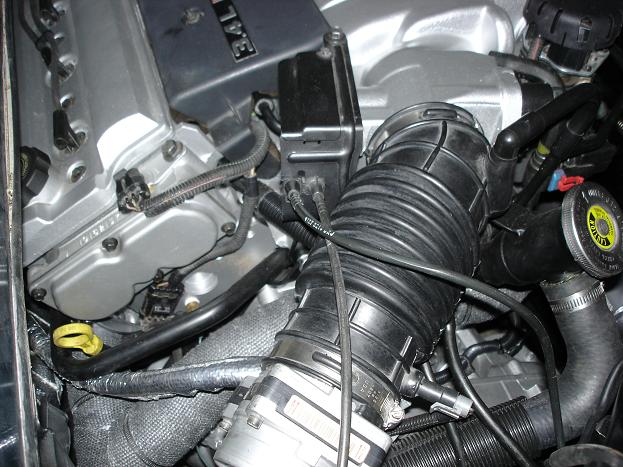
If you follow the hose coming off the pump near the top of the pic, you will see it goes to a valve. That valve is a vacuum actuated valve. It then goes to a T and is split between the two manifolds. The other hose coming off the vacuum pump is just the intake hose.
The vacuum actuated valve is controlled by an electrical solenoid. That is the solenoid on the 3.4 wiring diagram. The smog pump that I just bought came with that vacuum solenoid but I believe any vacuum solenoid can be used. That solenoid draws vacuum from the intake which is shown on the 3.4 vacuum diagram on the bottom going to the "To Air Control Valve".
The smog pump I got is from a 2001 Silverado. To wire it up, I will just tap into A18 of the ECU pin and a 20A fuse. Then add the vacuum line to the vacuum solenoid. Wire up the vacuum solenoid as it shows on the wiring diagram and it should be a done deal.
I hope that help. I am 90% certain this will work. I won't know for sure until I hook everything up but the concept is solid in my mind.
edit: The vacuum pump with a relay, vacuum solenoid, and vacuum valve I got locally for $75 at Subway Truck Salvage on my lunch break.
[This message has been edited by Doug85GT (edited 11-28-2007).]
I am looking at the wiring diagram for the air pump right now. Pin A18 from the ECU is the control for it. The ECU controls the air pump so no timer circuit is needed. The ECU activates the relay by providing a ground for the relay control circuit. Doing so turns on the air pump and actuates the air control solenoid at the same time. No timer curcuit is needed. The soleniod is a simple on/off soleniod. If we can just find an air solenoid that accepts 3/4" heater hose, then the problem is solved.
This is correct, the ECM controls the airpump. I j ust built a harness for a Lambo replica with the DOHC and its a CALI car so it has to have the pump. The pump and solenoid needs to be wired up to a relay, 12v power and ground.
[This message has been edited by Erik (edited 11-28-2007).]
Eric - can you pass on to us the diagram? Whats the vacuum line for that connects to the diverter? Were do we pull the vaccum from?
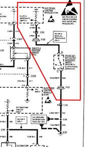
The diagram is page 1 of 3 of the 3.4 DOHC Engine Management Wiring Diagram. If you follow Pin A18 near the middle of the page, you will see the circuit.
The vacuum line is on the standard 3.4 DOHC manual transmission diagram. It is the very bottom vacuum line on the diagram and it draws vacuum near the MAP sensor. I am not sure if it T's off the same line as the MAP sensor or if there is a nipple near there that it draws from since I can't see the engine right now. The diagram shows it going right to the MAP sensor.
Both diagrams can be found in the big post on page 1 of this thread.
Eric - can you pass on to us the diagram? Whats the vacuum line for that connects to the diverter? Were do we pull the vaccum from?
sure I will later this evening when i get a chance
When the solenoid of the diverter is energized, intake manifold vacuum is applied to the bottom of the diaphragm and pulls the valve open against spring tension, allowing air to flow from the clean side of the air cleaner to the exhaust ports.
The diagram is page 1 of 3 of the 3.4 DOHC Engine Management Wiring Diagram. If you follow Pin A18 near the middle of the page, you will see the circuit.
The vacuum line is on the standard 3.4 DOHC manual transmission diagram. It is the very bottom vacuum line on the diagram and it draws vacuum near the MAP sensor. I am not sure if it T's off the same line as the MAP sensor or if there is a nipple near there that it draws from since I can't see the engine right now. The diagram shows it going right to the MAP sensor.
Both diagrams can be found in the big post on page 1 of this thread.
Thanks Doug for the help. I'm going to work on this Sat if time allows.
I posted this in the tech section, but thought it should be archived here as well.
THE CLUTCH ANTICIPATION SWITCH
First off, I have no idea what the clutch anticipation signal to the ECM (pin D22) does. Raise the RPM? Enrich the air-fuel mix?
All I know is there�s a input to the computer, so I�m going to hook it up. I�ve seen it mentioned in a few threads and recommendations of �wiring it to the cruise control clutch cutoff�. That won�t give the proper signal and will probably disable the cruise control.
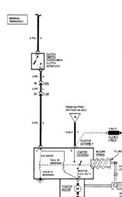
So here�s what I�ve found. There are two different switches on my clutch pedal. When the clutch is depressed the upper switch, which energizes the starter, is closed.
We can forget this switch for this discussion.
The lower switch on the Fiero pedal is the cruise control cutoff (on cars with CC). This diagram is from a Lumina service manual, but the layout is typical.
Note also that it�s in series with the brake switch CC cutoff. No way to make this work for the ECM signal.
This is a diagram from the Lumina service manual for the D22 signal. Note the ECM is seeing a ground until the pedal is depressed.
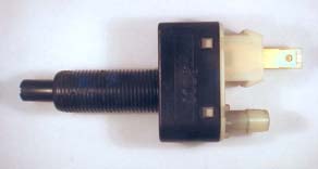
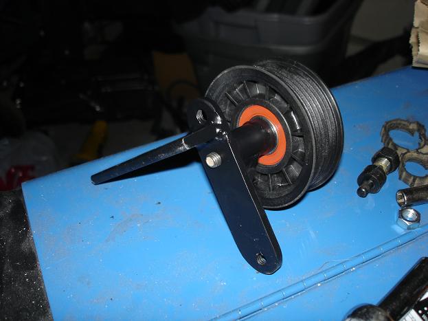
I noticed in the two lower diagrams the switch poles are marked A & B and C & D. I ordered a 1992 Z34 five-speed clutch and here�s what I got:
It has four terminals marked �A B C D�. There is a male half of the connector included, but not shown.
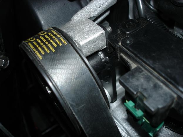
For comparison, this is the Fiero switch:
Only two terminals (This is a 1988 GT switch, others may be different).
So, what difference will it make? I�ll let you know when it�s running.
Neil
[This message has been edited by sspeedstreet (edited 11-30-2007).]
the clutch switch as used on the lumina, gtp sends a signal to the ECM when the clutch is depressed, the same switch also is used to disengage the cruise when clutch is dpressed hence the 4 pins, 2 separate circuits ..The Fiero clutch switch can be used as the ECm only needs to know if the clutch is engaged or not by grounding or opening the circuit
[This message has been edited by Erik (edited 11-28-2007).]
The Fiero clutch switch can be used as the ECm only needs to know if the clutch is engaged or not by grounding or opening the circuit
I don't believe this is so. The Fiero CC cutoff switch is seeing a voltage, not a ground. Plus the ECM D22 would get the same signal when the brake was depressed.
[This message has been edited by sspeedstreet (edited 11-29-2007).]
I don't believe this is so. The Fiero CC cutoff switch is seeing a voltage, not a ground. Plus the ECM D22 would get the same signal when the brake was depressed.
what you need to do is run a ground to one side of the clutch switch ( its a double switch ) that is not used and the d22 wire to the other terminal on that switch. The other side goes to the cruise control if you have it and brake switch
[This message has been edited by Erik (edited 11-29-2007).]
what you need to do is run a ground to one side of the clutch switch ( its a double switch ) that is not used and the d22 wire to the other terminal on that switch. The other side goes to the cruise control if you have it and brake switch
Maybe some of the clutch switches were different, but the one on my 1988 GT 5-speed has only two contacts and they are for the CC. I posted what I did to try to end the confusion (at least in my head) over how the D22 is correctly wired to the clutch pedal. Your two responses are again confusing a simple statement on my part: IF your clutch switch has only two terminals you will need one with four terminals (double switch) to wire the D22.
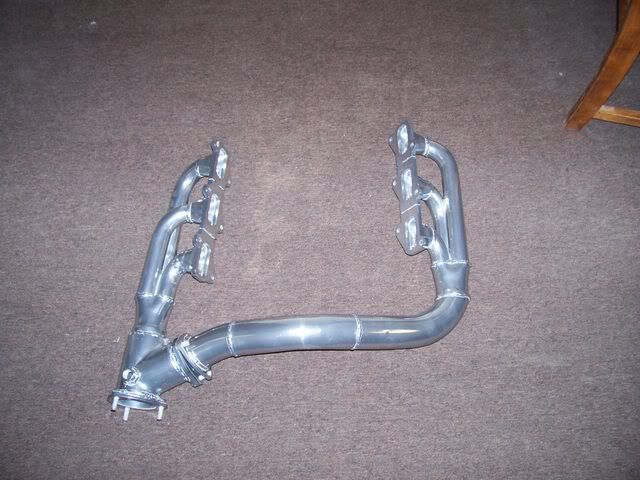
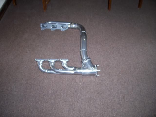
Hey everyone....Sorry I haven't been around for a long time but life is too busy for me. Just thought yall might enjoy the pics. But before you ask..I haven't had much time to do anything as far as making a set....but feel free to copy for yourself.
had to take back out because the header wrap was eating away at the metal so i decided to ceramic coat them before they rotted away.
I am actually more interrested in your short runner intake. It looks like you chopped the bottom of a 96-97 intake for the runners. What did you use for the surge tank?
Yes thats the stock 2.8 t/b. Yes that was his plan when building it, he was going to go forced induction. I'm not sure if he still plans on forced induction.
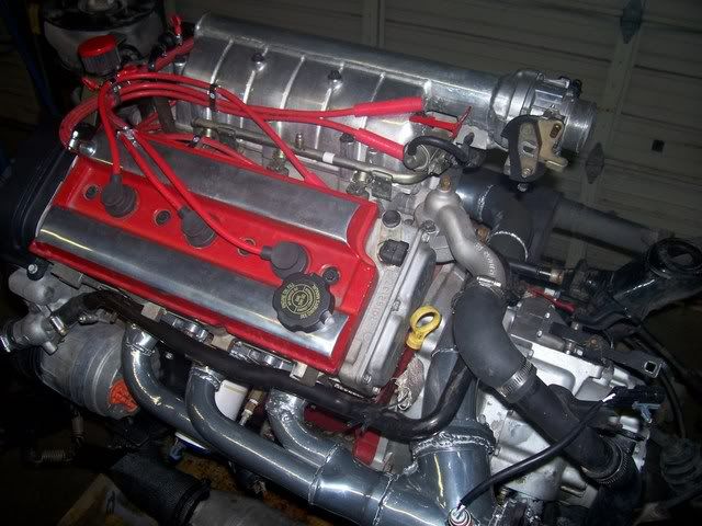
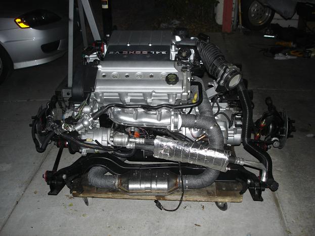
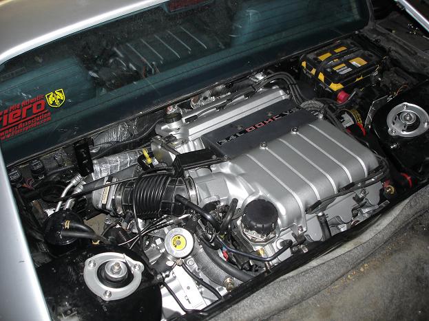
After 13 months of hard work, It's finally ready. Tomorrow I have scheduled the Go Live of my 3.4 DOHC 88 GT. The engine swap is practically complete. The car is far from show ready, but it is ready for the road. I will post Vids of course, but for now I have a few teaser pics. It really came out beautiful. An un[Fiero]educated mechanic could never tell the engine didn't belong in the car, that was the goal. It's way too clean to pass off as origional though. Tomorrows agenda is to make the crank trigger wire, and put fluid in the transmission and coolant. Then start the beast up and test drive it. Now for a few pics...
First I would like to start with the engine just prior to the install, see it from all angles.
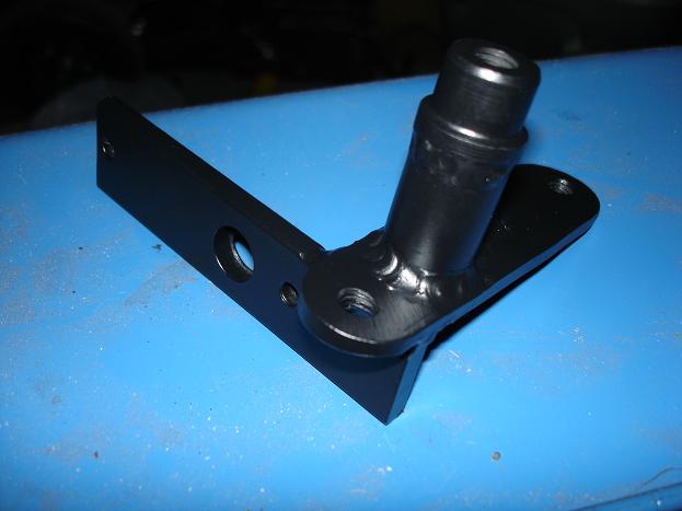
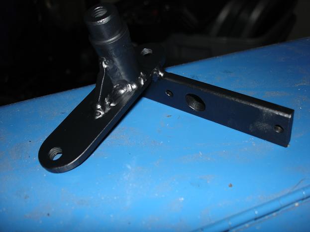
Heres my Power Steering Delete bracket. The extra piece of metal is a MAP sensor mount. Though the car does not require a MAP sensor, I felt I would pre-wire, plumb and mount it as if it did. I might need it in the future
In place
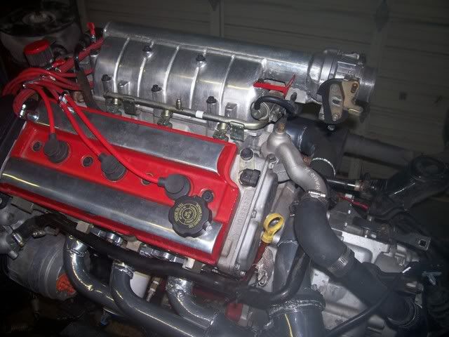
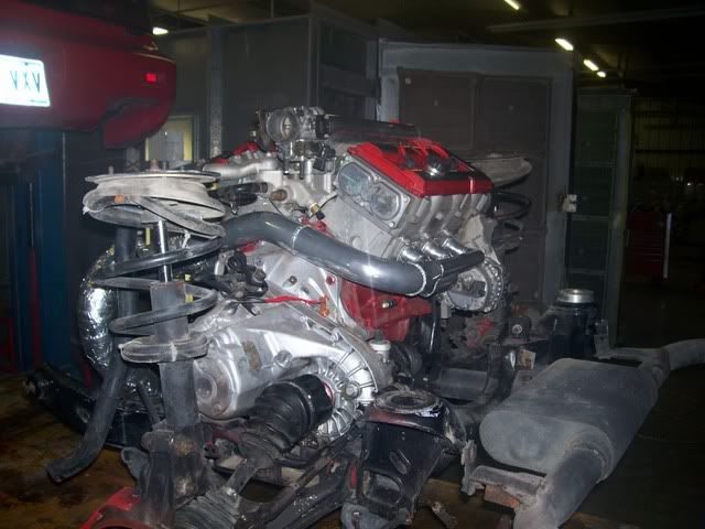
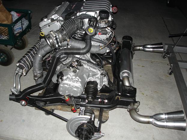
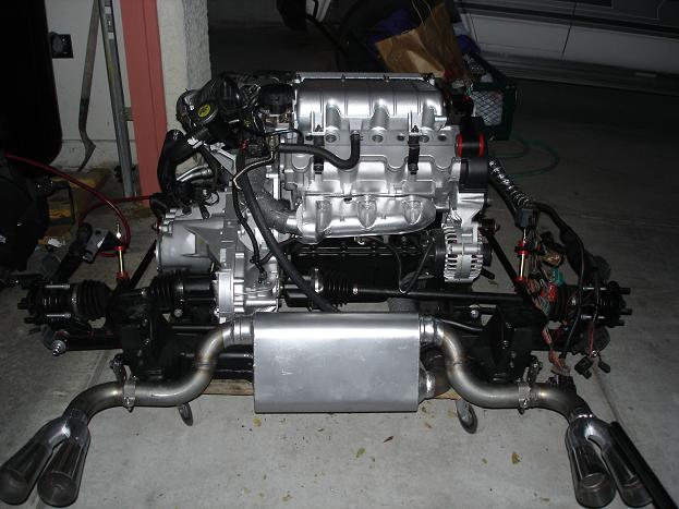
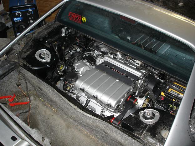
Overview shots
Left side, Notice the Dipstick, I fabricated the entire dipstick from parts of another. I found I had to use the 96-97 3.4 DOHC dipstick itself, it had a straight (non twisted) stick. Also, you can see how I utilized a stock 4 cylender Fiero water neck and hose.
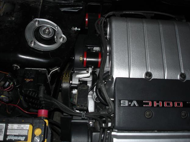
Right side, The Dogbone is the real beauty of this image. Also, note the coil pack. I cut up and re-welded the 3.4 DOHC's coil braket, and made it fit snugly to the fiero's strut tower
yes it is a 2.8 tb. it is smaller than the stock one but actually increses the low speed velosity. Hurts in the higher rpm range a little but not much. the tank is a 2.25" ID pipe. I am thinking about going with a vortech supercharger but still thinking about it.
After the ordeal I have been through, using that ear to brace the engine looks ludicras! I sincerely hope that it does not break the power stearing mount should it flex. I anticipate it will though. I don't see polyurithane mounts, which worsens the scenario 4 fold. Just consider the work that will be required to take the engine out to replace the front cover should it break. I've had to do it twice now. I'm peraniod to my limits now. The ear the bolts to the block is so thin.... Please do everything you can to ensure that swap lasts as long possible. I know how hard you've worked on it.
Sorry to complain, the swap looks beautiful. I just don't want you to have to go through what I have.
Hey procarnut, I too am interested in the shortend UIM. Can you tell us the process or what you charge to build one? I am in cali and need egr (unless I delete it ) but then every two years I would have to swap it out. (PAIN)
Sorry again so long to respond. Life never seems to slow down.
I took a 96 3.4l DOHC upper intake and cut it about 1/2 inch above the highest manfold bolt. Then i picked up a 2.25 inch ID aluminum pipe and cut it about 5 inches longer than the runners. Then I put the pipe in a mill and shaved off the lower part untill it was wide enough to butt up to the intake runners. We welded it to the intake peice. Capped off the end (welded a flat aluminum plate). Then I chopped off the TB flange off the old intake and welded it to the other end. On the bottom behind the TB I made a rectanglular block and drilled a hole for the IAC bypass tube, three hose ports (pressed in inlets for the vacuum lines), and drill a hole into the intake tubeand welded that block on top of the hole. This allowed me to connect the IAC tube, brake booster hose, MAP sensor hose, and fuel pressure regulator hose. On the other end of the pipe (blocked off with a plate) we drilled a hole and put in the inlet for the PCV valve. Once all the welding is done, then is the time to polish out the aluminum for the chrome look.
Hope that helps. Later I'll see if I can find pictures to post.
Bob
So how well does it run with that intake???
[This message has been edited by Erik (edited 12-09-2007).]
I really cant say by comparrison. I did ride in another 3.4l dohc butit was an automatic. Mine is a std. trans. I can say that once i slam the throttle it picks up and moves without ANY hesitation. Really by design throttle snap is quick. Smaller intake creates alot of volocity at low rpms. Where a large intake have volume but low velocity. Velocity = quick throttle snap. I was building for a Turbo but decided to run it in first before i took it to the next level. There is another thread about building a large intake, and he explaines it very well. I am thinking about building one larger to see what the diff. would be like but i expect a flat spot in acceleration. I think if everything was stock i would loose top end power but I have nothing to compare too.
I wish I could say yes.....but time is one thing i don't have. Fact is I've been working double to triple loads at school. Too many students to keep up with in my mind. I've spent three weeks to build/machine front caliper brakets for my corvette brakes and i haven't even installed them yet. I changed my mind to reclock the calipers to 2 O'clock instead of 3 O'clock for the front. I am currently working on a template to install the C5 rear brakes WITH the stock C5 parking brake assy. It's a long process. I'll post specs of each when I have a good working model.
Concerning the intake...I would change it to a larger tank and TB. I would stick to the same runners as they are..shorter. I will eventually go with a super charger ot turbo if i get time too.
It didn't start on all cylinders on the first startup. After I let it run for a little bit, I shut it off, and the next time I started it, it was running on all 6 and sounded great. I guess the new injectors didn't work immediatly, typical. I also forgot to connect the MAF and IAT, I had put the intake on and forgot to plug them in. All that is sorted out now. It is going to be quite a while before I am driving it around routinly. As of today, the engine has about 100 miles on it. I had a couple of issues too: The waterpump was missing it's internal seal, I didn't even get to fill the engine with coolant all the way before I was changing a waterpump. The alternator. I cleaned up the old one, and installed it. It didn't work. Good thing its easy to change, So easy I let a good friend change it. The Accessory belt, Since I let a good friend change the alternator, he put the belt on with one rib hanging off the alternator, and it shreaded within the first 50 miles. Oil pressure sensor, it didn't work. The clutch slips in 3rd 4th and 5th. I havn't been making it slip, but I can feel it give out. but I am pretty sure this type of clutch is going to take a while to break in. So, you can see, its all about the little, mostly electronic isssues. All in all, it went well.
Do you have any motor movement? I saw that picture of the dogbone again and a shiver went down my back. I do hope it holds well for you.
When it first cut off I was thinking VATS- but then after a while it stayed on and I was like "Oh never mind he has a chip! yay" The hissing that you hear at the beginning is because of the MAF being unplugged. If you go unplug it right now, it will hiss just like that. I always thought the hiss was sort of cool. I'll just install a switch I can flip while at stoplights, that way it will intimidate all of the Honda's.
The oil sending unit; what do you mean it doesn't work? As in a wire is cut, or is the gauge pegging? From the picture you posted it looks like that's the stock "light" gauge that comes with the motor. Hard to tell if the shaft isn't longer. Anyways, you might want to fix that soon so that you know you have good oil pressure.
We shredded a belt also within the first 50 miles.
The clutch issue is curious. I've had experience with both a stock Borge Warner clutch and a Spec III, both held pretty firmly when new. I hope that the slipping is normal, because it would really suck if you had to pull it back apart soon.
quote
All in all, it went well.
Your swap looks awesome man!! You've done a terrific job! Can't wait to hear about when you have everything in top working order!!
When I did my swap at first (within about 200 miles) I shreaded two belts. One from the P/S pump going (before I put an idler in) and the other from a mis-aligned idler. The second one happened at the drag strip. I drove the car home 75 miles with half the belt missing. Haha... young and dumb.
Looks to me (from what I can see) that you have the dummy light oil pressure sending unit on there. I ordered one off a 92 lumina that works with the gauge!
You're swap looks awesome and clean (as expected), and I'm glad to see that it runs! (actually it was kinda funny, I was on youtube today and searched 3.4 DOHC and saw your video, then saw it in here!) Good luck with the clutch BTW, sounds like an unusual problem!
BTW, does anyone know what application injectors for the 3.4 cross refrence with? EDIT: I should mention, I'm asking about aftermarket injectors. I've heard 3800 SC (which I've ALSO heard are too short before) and Mustang (although I'm unsure if were talking 4.6 or 5.0 and which year Mustang). Dont really want to have to modify the fuel rail for them, so it would be nice to know what injectors are the same physical size as the LQ1's. Thanks Guys!
[This message has been edited by fieromadman (edited 02-12-2008).]
Engine movement is absolutley minimal. But I'd be lying if I said it sits perfectly still. I stand strong in my theory that the dogbone method is acceptable If and only if it does NOT apply any twisting force to the hook. I hope I am right.
quote
The hissing that you hear at the beginning is because of the MAF being unplugged.
Bear in mind I was only running on a couple of cylinders on first start, so the IAC opens up a bunch more to compensate for the drag of some dead cyl's, making it hiss obnoxiously. A missing MAF will do the same because it puts the IAC, Fuel injectors and Ignition timing at safe estimated values. (Pig rich, IAC half open, timing conservative)
quote
The oil sending unit; what do you mean it doesn't work? As in a wire is cut, or is the gauge pegging? From the picture you posted it looks like that's the stock "light" gauge that comes with the motor. Hard to tell if the shaft isn't longer. Anyways, you might want to fix that soon so that you know you have good oil pressure.
We shredded a belt also within the first 50 miles.
I have had zero harness issues. Which, I have been absolutly thrilled about. Got it right the first time! I used the 3.4 DOHC's Oil pressure sensor. Either it is broke, or it is incompatible with the Fiero's gage. I have a new stock 88 GT sensor to replace it.
quote
The clutch issue is curious. I've had experience with both a stock Borge Warner clutch and a Spec III, both held pretty firmly when new. I hope that the slipping is normal, because it would really suck if you had to pull it back apart soon.
The clutch thing scares me a little. It is a full face kevlar disk and a stock pressure plate. Iv'e been told these take the longest to break in. I've only got 100 easy, mostly highway miles on it.
quote
Your swap looks awesome man!! You've done a terrific job!
Thank You! Right now, my focus is on rebuilding the doors and the interior. It is coming along beautifully. I am also sinking the windows the last half inch. I've been itching to do that to a Fiero for 10 years. I've got MrMikes Leatherette covers in stock 88 style Grey, on 84' speaker seats. I did the headliner in black, and I have black Fierostore floormats, which I absolutly love. I just hope I can keep them clean. I will leave the outside of the car as ragged as it is now for a few more years. But it should be one heck of a drivers car.