When I told my fabricator that I wanted to make a cover for the rear bank he laughed at me. "Why do you think they put O-rings on the plug stalks?"
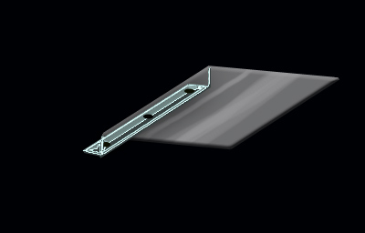
I left it at that. Since then I have watched standing water well... "stand there". If the plug stalks have good o-rings on them I don't see water getting to the plugs. Buuuuuuuuuuuut.... I can see the need for precation. The easiest solution, for you or even a stock decklid, would be to attach a rubber strip to the under side of the trunk and then to the firewall. If you want to be creative than you can also make a cover out of stainless steel. Hold on and I'll show you what I mean.
Injen makes several of these and they look awesome. Perhaps you could make one that looks just a good and then have Fiero engraved, or something similar (3.4 turbo )
I had a cover exactly like the one that you show there made up for when I had the 91-95 intakes. I didnt have anywhere to attach it to the 96-97 intake setup since the bolts on the fule rail dont exist. So keep that in mind. Also, Kohburn came up with some great material to attach to the underside of the decklid/firewall. I have it on my car. I know a vendor makes these, but I dont remember who.
BTW, dont you hate working on Fiero's sometimes? Ive been wrenching on mine for the past week and a half straight except for when I am at work. I hate it. Damn those 3.4 DOHC's cracking my getrag case.
------------------ --180* t-stat, cams, 96-97 intake swap, FFP pulley, A/C Idler, flowmaster exhaust, EGR delete, K&N filter, chip-- --Check out the Fiero Kingdom!-- Beater: Flat black 90 CRX with a JDM D15 VTEC <--ballin'!
Question for ya guys, with tapping that upper P/S bracket hole for the idler pulley and making the A/C delete bracket that was listed a couple posts back, what kind of serpentine belt application should I be looking for ?
That's your fault not mine. And no I got the entire cradle out of mine and on the floor in an hour last go round. I'd image it would have taken about another hour to replace the trans, since I would have to drive to the machine shop to get the flywheel resurfaced. Then about another hour getting it back in... what's your holdup.. ?
I had to pull the harmonic balancer and intake manifolds and I ported the exhaust manifolds and painted stuff and fixed some wiring issues as well. Plus I upgraded brakes and tweaked the exhaust, had the cradle welded and fixed some engine mounts. And I'm still bitching... sorry forum
But seriously, it was good to have it all back together and then I drove it for the first time and got a 10 day on the first trip.
So moral of the story is: Fiero for sale, best offer.
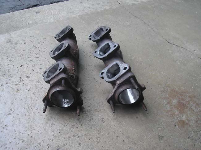
Nice new ported exhaust manifolds!!
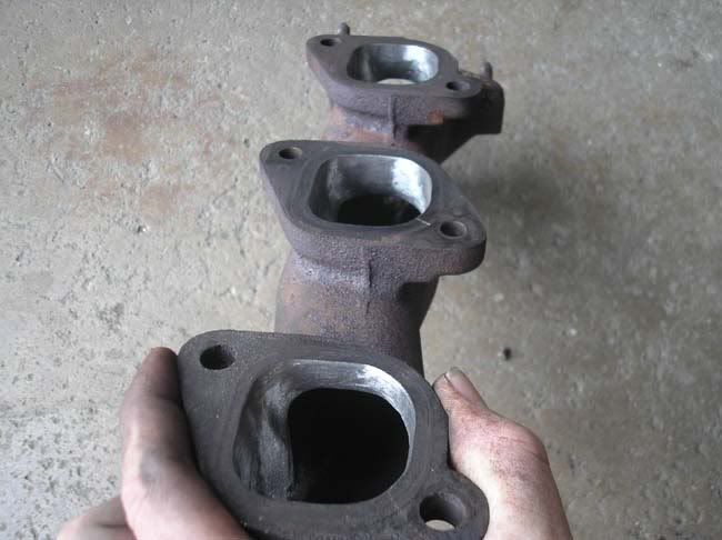
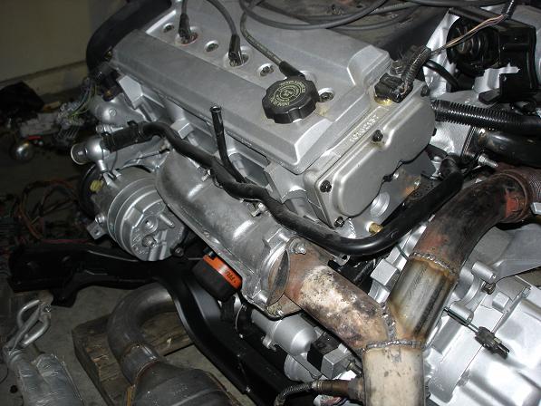
Along the same lines, for anyone running two front manifolds on the engine, although the bolts line up right for the manifold, the ports dont. Gasket match them before you put them on. Heres some pics:
Front and rear are ported, the rear is on the left side
Front:
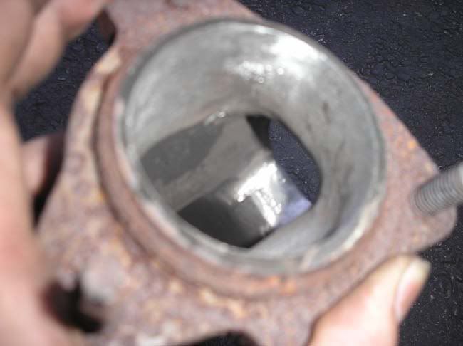
Rear (enlarged mainly on the left)
Another view
------------------ --180* t-stat, cams, 96-97 intake swap, FFP pulley, A/C Idler, flowmaster exhaust, EGR delete, K&N filter, chip-- --Check out the Fiero Kingdom!-- Beater: Flat black 90 CRX with a JDM D15 VTEC <--ballin'!
Ahh so that's you're culprit... you took everything apart. You can't complain about having to take it apart if it didn't break or need work (performance work you can't ***** about ) haha
There is a real concern about water getting into the spark plug area. I first owned a 1992 Grand Prix with the 3.4L DOHC engine before I installed the same engine into my Fiero. In the Grand Prix I used to get water into the opening of the spark plugs all the time every time I washed the engine. I never sprayed water directly at the spark plug wires. The water would just pass right by the O rings. This happened even when the car was new. One of the best shields that I have ever seen, installed on a Fiero, was a rubber strip that bolted just under the rear window and was attached to the rear deck on the Fiero. This kept all water from falling onto the valve cover and onto the manifold. Water on the manifold was one of the major problems that corroded the rear manifold on the stock V6. When cold water fell onto the front manifold it caused the manifold to warp. This is why several stock V6 Fieros had a ticking sound coming from the engine compartment. The ticking sound was the very common manifold to head exhaust leak. Fixing it was a problem due to corroded bolts.
is it possible to run a simple breather off of the oil ventilation thing thats bolted to the block? and also did you guys run all the factory vaccume lines, I am also thinking of getting rid of all the coolant flow passages that flow to the intake plenum just for less leaks headaches after all the throttle body cooling doesnt do much especially when its a strictly summer car
Well Ifinally got around to installing the wire harness I had Erik make. All went well but there are 3 connectors that terminate by the starter that I can't seem to find a connection for, any help appreciated. hope the pics work
Well Ifinally got around to installing the wire harness I had Erik make. All went well but there are 3 connectors that terminate by the starter that I can't seem to find a connection for, any help appreciated. hope the pics work
thanks dan
The pics are blurry but it appears like you have coolant temp sensor connector that goes to the front head ( one terminal) , a manifold air temp sensor connector ( 2 terminal) and a reverse switch connector ( 2 terminal ) that goes to the trans ..
sorry about the pics, Because the pics are blurry I wrote down the color and wires of the connectors
1 black plug 2 wire, green and blue 1 grey plug 2 wire, brown and black 1 black round plug 1 wire, green
Eric,or anybody, correct me if I'm wrong, isn't the air temp sensor located in the maf area or is that located in the intake "pipe, duct". which makes sense because that plug (brown/black wires) are rather long. Back up light switch, i'll have to look for that all i see on the tranny is the vss (muncie). the green wire one, might reach the sensor in the last pic.
1 black plug 2 wire, green and blue Reverse switch, goes to the corresponding connector on your transmission
1 grey plug 2 wire, brown and black Manifold Air Temp "MAT" sensor connector
1 black round plug 1 wire, green Temp sensor connector, goes to the sensor located on the front head ( closest to the back window, firewall ) at the back of the motor ( transmission side) I noticed you have a picture of the temp sensor located on the head but the wire and corresponding mating connector is missing on the sensor. You will have to get a new one.
I made the wire to the MAT sensor connector wire longer so you could choose where to put the sensor along the air intake tract
[This message has been edited by Erik (edited 06-15-2007).]
Ok next question, lets talk plumbing. (95 engine, 86 4 banger). Ok I looked at the pic on page 9, looked at lilferari's site (bcuz my rebuild models his), and I can see were the rad. in and out hook up. I also see that I had the heater lines confused. I currently have the heater inlet hooked into the plenum nipple, I see that it needs to be moved which still leaves me with my question. What to do with the coolant nipple in the plenum, where does that connect to now that it is free from the heater pipe.
This may be a stupid question but ... what does it matter which way the coolant flows through the heater core? Mine's an 88 and I had to plug the inlet (from the heater core) going into the water pump because the return hose on the 88 is ported into the right side coolant tube. As long as you have one side of the heater core hose going to the pump outlet side and one hose going to the pump inlet side I don't see what difference it would make which way the coolant flows through the heater core.
There is a slight difference. One of the hoses is a 3/4" and the other is a 5/8"
The reason for the difference, is the return line is larger to prevent a rise in pressure within the heatercore due to high flow rates. I will just say this up front. My 3.4 DOHC, and my Quad 4 have both managed to pop heatercores even flowing the correct directions. I usually now put a 3/8" oriface (Quad 4's have them in the water neck from the factory) in the heater core feed line at the thermostat area to help reduce the flow induced pressure in the heatercore. At least the cores are cheep and really easy to replace. Thank you whoever designed that
The 3.4 DOHC's have a heatercore return port threaded into the Timing housing, since you do not have a dedicated return line (it plumbs into the radiator return just before the waterpump on the car) you should plug off this return port near the waterpump like you already did. Then, you only have to plumb the engines heatercore feed line to the one line that used to go to the water neck on the V6, or to the intake manifold if you had an L4. This is where I reccomend putting a 3/8" oriface.
If you have an older Fiero, they actually had the return line feed directly into the engine, in which case you should plumb both lines accordingly. I do reccomend keeping the factory line that goes from the throttlebody to the inlet for the waterpump in place. It is not really beneficial to defeat this. But you can if you really want.
I don't actually understand why you say you would have the coolant flowing through the heatercore backwards. There is no good reason to do that.
ok, if I am reading fierobsessed correctly, then the nipple above the waterpump can be "blocked" off, and not used as it is only the return for the heater core. Then plumb the heater core return line into the pipe underneath the thermostat housing.???
ok, if I am reading fierobsessed correctly, then the nipple above the waterpump can be "blocked" off, and not used as it is only the return for the heater core. Then plumb the heater core return line into the pipe underneath the thermostat housing.???
dan
Nope...on your 86 the pipe that comes out from under the throttle body is the feed to the heater core. This is hot coolant right out of the engine. The nipple that you're talking about plugging is the return from the heater core....the suction side of the water pump. The 88 is the only one you need to block off the port by the water pump because the return line is fed into the right side coolant tube just in front of the rear wheel. Check out that diagram on page 9 and you'll see.
It's been a long time since I dealt with a 4 cyl. car but I think there's a solid coolant tube that follows the right side frame rail to the back of the engine compartment and would connect directly to the water pump on the 4 cyl. engine. This is the return line that gets plumbed into the nipple near the water pump.
The hose that was originally connected to the head near the thermostat housing on the 4 cly. gets connected to the outlet tube under the throttle body. This is the feed for the heater core.
Fierobsessed, Makes sense to me although I don't understand why you would have a problem with over-pressuring the heater core. With the larger outlet on the heater core there is no reason it should see any more than the design pressure unless there is another obstruction down stream. Does the DOHC water pump work that much better than the 2.8?
I have been watching this tread for while now. I want to thank all of you that have posted your methods for doing the different parts of the swap � much appreciated.
I wish there was more on the wiring, especially the pre 94 setup I would have loved to see a complete C203 and C500 side by side wire line up for us PHD mechanics (Put Here Dummy)
I�m doing a 94 LQ1 into an 88 manual using a 92 harness and ECM. I�m OK with the mechanical parts of the swap but wiring is kicking my butt. I�m in the process of doing it myself using some of the links posted here but have never felt so dumb in my life. I�m going to go home tonight and make a punch list of all my problem area�s on the harness and again try to figure them out.
I�m doing a 92 harness and ECM because I�m in Calif. and wanted to avoid issues with SMOG.
Another area I�m having trouble with is the Air Pump sys. (must have air pump in Calif.) Can�t seem to find a set of manifolds with the bungs in them. I wanted to avoid having the manifolds welded to add them due to the issues with welding cast iron. Looks like I have no other option. Because the harness I have was off an Auto I need to add the relay wiring for the air pump sys. Another area that makes me feel stupid.
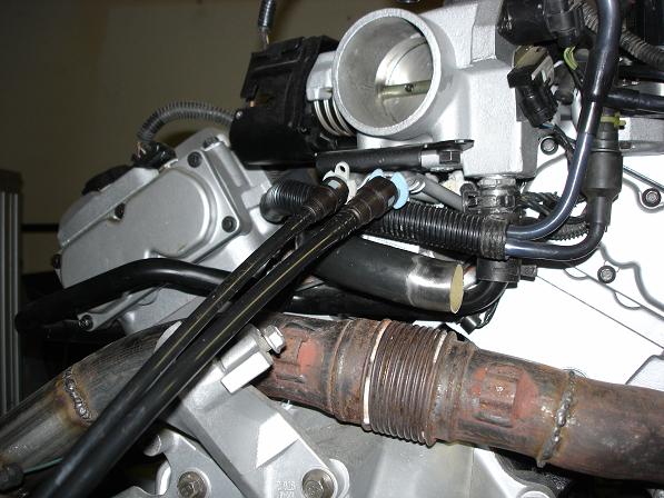
That's the Vaccum supply port for the brake booster.
I think this goes without saying, but, Do NOT, and I repeat DO NOT hook that to the heater core.
You will find on the firewall where the shift cable comes out, a hose or just the end of the metal line, you need to connect and run a hose or a hardline around the engine bay to the back wall where that nipple is.
[This message has been edited by Fierobsessed (edited 06-19-2007).]
CC Rider: Go have a look and get back to me here about what you think. I need input like: what would make it easier to understand; things that are confusing; thoughts and recommendations etc.
EMC209, the one I am talking about is circled in red. sorry it took so long to respond.
dan
Yes that is the vacuum port for the brake booster. As Obsessed mentioned, the other end of that you are going to connect to is in the middle of the firewall. The heater hose connects to end of the plenuim, right below the TB. The return will be on the water pump if your car is pre 88, and built into the return line if it is an 88 model. If you do not use the return you should cap the one on the water pump.
I have been watching this tread for while now. I want to thank all of you that have posted your methods for doing the different parts of the swap – much appreciated.
I wish there was more on the wiring, especially the pre 94 setup I would have loved to see a complete C203 and C500 side by side wire line up for us PHD mechanics (Put Here Dummy)
I’m doing a 94 LQ1 into an 88 manual using a 92 harness and ECM. I’m OK with the mechanical parts of the swap but wiring is kicking my butt. I’m in the process of doing it myself using some of the links posted here but have never felt so dumb in my life. I’m going to go home tonight and make a punch list of all my problem area’s on the harness and again try to figure them out.
I’m doing a 92 harness and ECM because I’m in Calif. and wanted to avoid issues with SMOG.
Another area I’m having trouble with is the Air Pump sys. (must have air pump in Calif.) Can’t seem to find a set of manifolds with the bungs in them. I wanted to avoid having the manifolds welded to add them due to the issues with welding cast iron. Looks like I have no other option. Because the harness I have was off an Auto I need to add the relay wiring for the air pump sys. Another area that makes me feel stupid.
Thanks again for all the great info !!!
I used non-AIR manifolds, drilled and tapped them for 1/8" NPT, then used 1/8" NPT to -5AN adapters, removed the stock fittings from the AIR pumps, and put on -5AN tube nuts and flared them. It works well and passed the BAR inspection.
I used non-AIR manifolds, drilled and tapped them for , then used 1/8" NPT to -5AN adapters, removed the stock fittings from the AIR pumps, and put on -5AN tube nuts and flared them. It works well and passed the BAR inspection.
1/8" NPT
Steve - thanks for the help !!! So what is " 1/8" NPT" and -5AN adapters" 1/8" sounds real small because the stock setup is around 1/2" and only one of these going to each manifold. Did you put 3 to a side?
Emc209i - Thanks for the help. Have been on this forum for a long time, I am always amazed at the level of kindness from the group as a hole. Will look at it and give feedback. If I get a chance today I'll study it and ask questions. My next free day will be Sat. and I'll really look it over then.
Thanks for clearing that up, ya coolant into the vacuum system would not be a good idea, lol. I believe that does it for my questions, but who knows probally find something else this weekend that will confuse the hell out of me.
here is my contribution thusfar. on the link is some headflow data for the 96-97 lq1 heads which i do not see any of and i think these heads are superior. data supports what i suspected they kill the early style heads on exhaust. good flow ratios too. looks to be ideal for turbo engines too!
Took the first ride around the block in my DOHC 88 GT today. Aside from the speedometer not working and the tach reading about twice what the engine sounded like, everything went great and the exhaust sounds awesome even though it's a little louder than my neighbors would like. I don't understand the speedo problem because all I did was tap into the VSS wiring for the ECM signal. I reversed the polarity of the two wires running to the ECM (yellow to purple and purple to yellow) as instructed by Ryan (DarthFiero) and had him burn the chip. Maybe I hosed something up in the wiring. It was tough getting all the air out of the cooling system but after burping it several times and using almost 2 3/4 gallons of coolant it seemed to work as planned. It ran surprisingly well on 2 1/2 year old gas. Cudos to fuel stabilizer.
Let me know if anyone has any ideas about the speedo..
Don
[This message has been edited by SKIDMARK (edited 06-24-2007).]


 )
)