Heheheh, that hat looks quite familiar - anodized or painted? I thought about making a backing plate that hits all 3 holes in the C bracket, but I don't have a mill or even a drillpress here at home (next time HF has a sale...). So I figured this would be dirt cheap and too simple to not do.
As for the MAP - do you have the 91-93 motor and you relocated it, or did you get a 94+ motor? Mine has a MAP holder right on the vacuum manifold that plugs into the end of the intake plenum, though I wonder if it'll nail the decklid reinforcement spar since I haven't put my lid in place or try to put the motor in with the MAP installed. I might make some sorta MAP holder bracket to attatch to my re-bar later if I need to relocate.
*Yawn*. I am not a morning person. 10:23 and I'm back from taking care of a ticket (got off the hook!). Time for an update before work...
Ok, since my last update I've began trying to sort out my wiring. Taking a break from that, I met up with Steven Snyder and we went junkyard hopping for swap parts. Let me assure you that there aren't any TDC/DOHC cars in the Pick N' Pulls from San Jose South all the way to Newark, though I haven't checked the Pick Your Part on Mowry in Fremont yet. We managed to drive like a bat outta hell and get to Richmond 2 minutes before they started kicking people out - the yard where I pulled my LIM and injectors from the 95' Olds. Good times. Anyways, I scored a throttle cable from an 87 2.5 Coupe and the A/C Lines from the same. I also grabbed a C203 connector while I was at it. I'm lucky to have grabbed anything useful - I was having an episode of CRS (Can't Remember _____ ) that lasted all day it seemed like! Anyways, I got the throttle cable installed - not surprisingly, it goes right in place of my 87GT Cable as I expected but it has the "barrel" end on it required for the TDC. The A/C lines fit right on the compressor and look like they were purpose bent to avoid hitting the oil cooler and coilpacks and such - it's only a matter of bolting the other side to the cars hardlines, which I'm sure will go fine. I'll post the hose pics up when I get time to put the motor back in again.
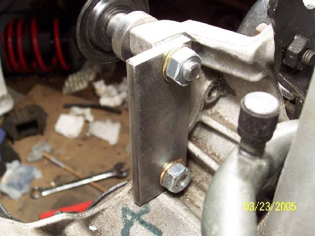
On another note, after reading Crzyones broken timing cover thread I realized some things: 1.) Stock Fiero mounts rock way too much (and sit too high); When I tried it with mine I could easily move the engine by hand 2.) Dodge mounts are *much* stiffer, but if you break the front mount (not designed for angular forces) you're f$%^&*ed, since the engine can eat pavement if it comes free! 3.) Dogbones do not like being twisted at all, and neither does whatever it's mounted to. All of this depends on how well the motor is supported on the bottom, and where you place the bone. 4.) I should kick myself in the ass and get to work on a 4th motor mount (under the A/C compressor where the "driveline absorber" shock goes on the 2.8) instead of going with 3 mounts like I planned. So I spent last night fabricating and completing my 4th motor mount.
This cable is interesting... on the end going to the motor, there's a joint you can separate that forms a small hollow chamber around the cable itself. Notice that the core of the cable itself doesn't separate, so I would assume that it's used to hold lubricant for the cable? I wish my shift cables worked like that: http://img.photobucket.com/albums/v249/pyromaniacal/TDC%20Swap%20Project/Throttle%20Cable/Coupe_Cable.jpg
You reach down under where the stereo is, and the cable is clicked into a square hole - depress the tabs and pull it out - But first you have to disconnect it from the gas pedal. Disassemble the gas pedal pivot (10mm bolts) and pull the pedal, arm, and end of the throttle cable out. You'll want to tie a string or wire to the end of your throttle cable, so you can pull the new cable along the same path, or else you'll have to fish for it. You can barely see it in the picture, but there's a fine wire tied to the end of the cable. I pulled the cable out, and tied the cable to the new one and pulled it back through. http://img.photobucket.com/albums/v249/pyromaniacal/TDC%20Swap%20Project/Throttle%20Cable/Throttle_Cable_Wire.jpg
I've been thinking of using sway bar endlinks instead of a dodge mount on that front side bracket.. they would be more resistant to being pulled on.. then just bolt a peice of angle to the cradle.. thats my current plan anyways.. my build is almost running parrallel to yours
IP: Logged
03:22 PM
gascarracer Member
Posts: 129 From: Batavia, Ohio, USA Registered: Apr 2003
Kohburn - that's not a half bad idea... I'm thinking it'll probably rip the bracket right off the cradle, or twist the mount until it fatigues (offset studs on the mount = torque) before it breaks the darn mount. We'll see I guess?
Gascarracer - thanks for the compliment - I'm hoping that this thread will show ALL the little things that nobody mentions while doing a swap. I knew things like "trim the lid hinge" and "cut the front mount so it bolts on" and stuff, but didn't know what it'd really be like and what to expect. Hopefully I've spelled it all out for people so they'll know what's involved!
Kohburn - that's not a half bad idea... I'm thinking it'll probably rip the bracket right off the cradle, or twist the mount until it fatigues (offset studs on the mount = torque) before it breaks the darn mount. We'll see I guess?
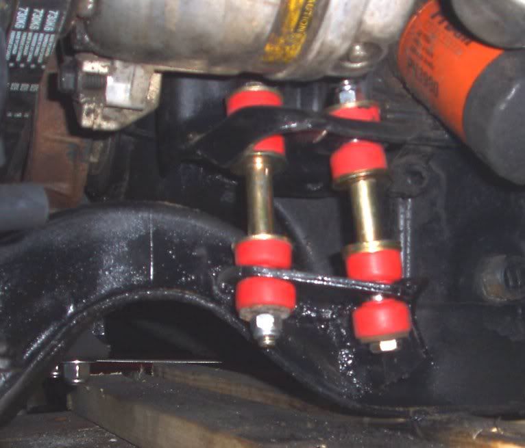
went ahead with my idea last night and it turned out pretty good - I'd almost wager that a dogbone isn't needed but i'll use one anyways
I cut up the brace that attached the 2.8 dogbone to the front head of the 2.8 and used its nice 1/4" thick steel to form a rather ridged bracket on the cradle then painted it gloss black also.
I see what you meant now - what a cool idea. That sure does away with having to make a flat surface to mount a dodge mount against. With all 4 mounts in place, I can't even move my motor. I can try to rock it at it's resonant frequency, push or kick it, and it won't move. I bet yours won't either. Even so, I bet it'll move a couple inches under WOT acceleration. I'm hoping that the dogbone failures I'm seeing are the result of going with 3 mounts, and/or using stocker 2.8 mounts.
BTW - do you have any reinforcing gussets on your cradle side bracket? I would be inclined to think that it'll flex and eventually fatigue the weld or the metal otherwise.
yeah you can see it on the right side of the bracket in the first picture.. I put it there because it allowed the longest gusset.. glossy black does make it harder to see things doesn't it
I had the last couple of days off, so I've gotten more stuff done. I started out by taking my rusty exhaust manifolds over to the carb shop I used to work at and threw them in the bead blaster. I took them home and cleaned them with carb cleaner, burnt the solvents out, and then painted them with silver VHT Flameproof coating. Note that this isn't high temperature paint as I've seen tried before - It's no good until you bake it until cured. I used the stuff on my 2.8 manifolds and it held pretty darn good until water got on them when they were hot. This time around, I suspect the much more porous cast iron will soak it up like a sponge and it'll stick better. It even supposedly has a little bit of insulation property, which can't hurt if true. Now I need to deal with fasteners - I never got ahold of studs, so I'm considering going with bolts for simplicity. If I go this route, I'll use some of those really strong socket head cap screws - the threads will strip looong before the bolt snaps off.
Aside from finishing the manifolds, I decided that I was way past due to jump into the wiring. Even though wiring is one of the things I've been fairly decent at, I've been working it up in my mind as "the big project". Energy drinks are great for motivation and focus... After spending hours labeling each wire with it's pin number and function, I decided that staring blankly at a 10 lb birds nest of wire and the schematics is about the worst thing I can do. So I did the one thing that came to mind - reduce the wiring harness to a pile of connectors, and strands of wire. I realize that this is probably the last thing some people would do, but I always did better starting from scratch, since I'm forced to learn every part to reassemble it. I spent most of last night mocking up how I'd build the harness - temporarily twisting wires together with the insulation still intact to simulate the right lengths for each wire, and finding out which goes where.
It was when I was doing this mockup when I realized that this is pretty easy, actually. If you can focus on following one sensor or one wire at a time as you review the schematics, most of the wiring is just shortening wires, or connecting one wire to another. Furthermore, even on connections between the Fiero and TDC harness, many of the wire colors match right up. Cool. Even cooler, GM seems to have been pretty uniform in whether they ground a wire to activate something, or supply power to it instead, which is good.
Aside from wiring work, I also took time to test out my 87' Coupe A/C lines as well. They fit, but it's kind of close between where the A/C lines go and my fuel lines, though I can stick my hand inbetween them. We'll see how that goes... I tried reclocking the compressor, but then the lines interfere with the oil filter, so that's a no go.
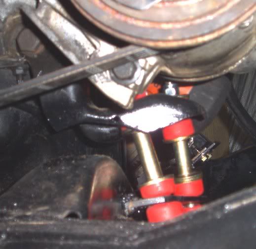
I ended up only snapping the vacuum fitting off... so I pulled out the superglue yet again. This is what I call "ghetto engineering" at it's finest. I almost felt overcome with the uncharacteristic urge to shout "WESSSSIIIIIDDE!" as I glued the MAP back together, but out of concern for the puzzled reaction I'd get from my neighbors, I declined to do so... http://img.photobucket.com/albums/v249/pyromaniacal/TDC%20Swap%20Project/General/Ghetto_MAP.jpg
I decided to see how the 87' 2.5 Coupe A/C lines I grabbed fit. It turns out that they do indeed fit, as others have reported. The aluminum "can" tends to be a little close to where my fuel lines are, but I can stick my hand in between and don't think it's going to hit. I might try to carefully bend it back slightly just for good measure though. http://img.photobucket.com/albums/v249/pyromaniacal/TDC%20Swap%20Project/General/AC_Lines.jpg
This VHT stuff is supposed to be pretty good. On my 2.8 it held up pretty good, except that I coated it a bit too heavy (it'll blister), and I got water on the manifolds when it was hot. Even so they still look pretty presentable. I hope that the porous nature of cast iron will hold the coating better. http://img.photobucket.com/albums/v249/pyromaniacal/TDC%20Swap%20Project/Exhaust/VHT.jpg
I figure that I'm well over halfway done with the wiring - just another day or two and I'll be able to start her up! Woo-hah! And that concludes tonights update. Goodnight.
Originally posted by Blue Shift: ...... After spraying the manifolds down with carb cleaner, I realized that solvents were soaked into the porous cast iron, so I heated them up good to burn it all out:
you are, of course, using flame proof cardboard for a base, aren't you......
quote
Take (2) TDC exhaust manifolds, add (1) can of VHT coating, Mix vigorously. Put into oven at 200 degrees and bake for 30 minutes. Repeat at 400, then 600 degrees. Remove and serve while still hot.
This is interesting; I have seen the name before but not seen any results with it; it is a spray I guess so it will be a fairly thin layer - ??? is that right? Do you let it cool between heating cycles in the oven? Does it stink up the kitchen and thus endear you to your betters (yet again.... ) or is it fairly non-volatile that way? I'll be interested in how it works out. No primer; I assume it is MEANT to go on bare metal unlike the special rust coatings now. (3-5 components....)
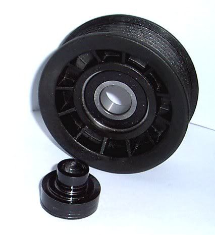
Kohburn: I am looking at the photo of the end links and am just not sure how much weight is on these ones in particular. Haven't gotten to that stage myself yet. I like the idea but wonder if these are more in tension (like dogbone) or compression? If compression, which I assume, then the weight is actually being carried "by" the interface between the end of the 'tube' (middle spacer) and the bit of the washer that actually contacts that tube. Is that tube 'seamed' or seamless? Dont' know if I am making mysefl clear here. I simply want to raise the question; play devils advocate for good reason; over repeated thousands of 'rockings' back and forth (which is to be expected). I am guessing that is actually a fraction of a square inch...... compared to the bearing surface of a more conventional mount. What do you think - maybe make up something that is a bit larger for bearing area? Don't know how hard it might be to replace this if it failed later on. You want to install and forget stuff like this I am sure.
the highest loads they will take will be from tension - the tube is non split.. the bearing surface is plenty large - just think about how much abuse the endlinks take on the suspension witht he whole weight of the car shifting to one side enough to sometimes even lift the inside wheel off the ground with a stif bar. should be plenty strong. the actual bearing area is the size of the poly bushing - there are thick washers that press on the poly.
just a side note.. in FWD ars the dogbone is in tension - but int he fiero its facing the opposite direction and is in compression
[This message has been edited by Kohburn (edited 04-09-2005).]
Blue: yeah i'm putting together a simple spreadsheet of connector wire to ecm wire so i can just dive into it this week.. hoping it won't take tooo long.
Fiero308 - Yeah, it's just a spray on coating. In fact, it says something like "apply coating sufficient to COLOR ONLY - building up a thick layer is not nessicary and is not advised as it may cause blistering". As for primer and such, it's made for use without a primer (which I didn't use) though I actually have a can of primer laying around that's made by the same people for just that purpose. As for the curing, I just cooked it in the oven at 200 for 30, then cranked it to 400, then cranked it as high as it would go for another 30. Gotta cure gradually or it'll blister off. The discoloration on the manifolds you see is organic matter smoking up in the oven... It doesn't really give off an odor or whatnot - the solvents evaporate before you cook it, and I think all the heat is doing is melting or glazing parts of the coating itself. It becomes solvent proof after curing. Try it in your wife/mother/girlfriend's oven at your own risk!
Wiring is coming along... little bit at a time. I don't really have much description of what I'm doing wiring wise because I have no way of knowing that I've wired it right yet (I've made one mistake so far - wiring the blue wire for the A/C pressure signal into the mini-harness plug instead of the blue wire for the MAP signal - D'oh!), and there would be pages and pages of information to convey across if I did. I think once I get it all hammered out, I'll write up a general guide showing what's involved and whatnot. It's not really hard - it's mostly matching wires up. Some of the stuff that's not shortening (as opposed to shorting!) wires or matching wire to wire includes connecting things like the fan control or the A/C control to the new ECM, so it can do the job, and getting your power distribution all set up. Here's some of the stuff that's been really useful:
I also managed to get ahold of the full DOHCFiero.com site, complete with pictures (which are probably worth more than the text to me!). If anyone wants it, let me know.
By the way, I have another CS alternator question. I see in more than one place that aside from the main charging terminal and the thick red wire coming from that, there's a red wire on the same plug where the Field and Light terminals are. Normally this has it's own fuse link and then splices into the main charging wire, then you have the light terminal connected to the idiot light. As for the field, I don't think it's used in my application - but I'm not sure yet. The car was wired for an SI alternator (87' GT), and I'm going to the CS that's on the TDC. Now here's the actual question - what if the stupid alternator plug doesn't have the red wire on it? On my plug, all I have is the F and L terminal wires! Now what? Do I just wire L to the idiot light, ignore the F, and wire the charging terminal to the battery (or starter lug connected to the battery +)?
my wiring question is.. there apears to be a coolant temp sensor on the top left front head of the engine.. but no fan switch or temp guage sender..
There is a coolant temperature sensor on the underside of the lower intake manifold, the wire/plug for it is in the same partial harness as the wiring to the injectors, EGR, IAC, and TPS. I believe this is the only coolant sensor, and the ECU uses this to give a dash reading, and for fan control, but don't quote me on this, I could very well be wrong.
There is a coolant temperature sensor on the underside of the lower intake manifold, the wire/plug for it is in the same partial harness as the wiring to the injectors, EGR, IAC, and TPS. I believe this is the only coolant sensor, and the ECU uses this to give a dash reading, and for fan control, but don't quote me on this, I could very well be wrong.
oh yeah forgot about that one..
is the one wire sender thats in the drivers side of the front head a fan switch? or a temp sensor? i should probably just pic up a haynes manual for the car my engine came out of
IP: Logged
12:59 PM
AaronZ34 Member
Posts: 2322 From: Colorado Springs, CO Registered: Oct 2004
I honestly do not know off hand what that sensor is for, but I know which one it is. I remember cuz I couldn't for the life of me get it out of my aqueous motor, it was so damn tight, and is still in the head. Id very well could be a temp sensor though.
IP: Logged
01:43 PM
gascarracer Member
Posts: 129 From: Batavia, Ohio, USA Registered: Apr 2003
I also managed to get ahold of the full DOHCFiero.com site, complete with pictures (which are probably worth more than the text to me!). If anyone wants it, let me know.
I would like to have a copy. What is the best way to do it?
I was hoping that the sight would reappear. Does anyone know what happened to it?
------------------ Ernie
1988 Silver GT One owner 47000 miles. Soon to be a 3.4 DOHC powered.
IP: Logged
03:01 PM
PFF
System Bot
Fierobsessed Member
Posts: 4782 From: Las Vegas, NV Registered: Dec 2001
The small coolant sensor sticking out the left side of the front head with a green wire is the temp guage sender. The sensor on the lower intake is the CTS for the computer (with yellow and black wires). The computer is wired directly to the fan relay (through the dark green wire on the C500) it takes the place of the "fan temp switch" that the Fiero had. So that should be it for coolant sensors.
The small coolant sensor sticking out the left side of the front head with a green wire is the temp guage sender. The sensor on the lower intake is the CTS for the computer (with yellow and black wires). The computer is wired directly to the fan relay (through the dark green wire on the C500) it takes the place of the "fan temp switch" that the Fiero had. So that should be it for coolant sensors.
thanks for the clarification
here is where it gets interesting
in the 3.1 turbo the ecm has fan relay control #1 and #2 - and it has a fan request signal #1 and #2 so it seems to require inputs telling the ecm to turn on the fans -
That's wierd, on my 92' Z34 ECM (16149396), it has a fan#1 and fan#2 control which connects up to the dark green/white wire that used to go to the termperature switch in the 2.8. Good news is the old temp switch would fail in short order, making nessicary the use of a manual fan override switch. Steven and I were talking about how some Fieros had two speed fans - it'd be trick if you could utilize both ECM fan outputs to control the fan in stages.
As for the temperature inputs... I'm pretty sure my ECM makes the call using CT sensor readings from either the sensor under the LIM (used for fuel/air data) or the sensor in the cylinder head (used for the temp gauge).
Having at least a little (probably a lot) of knowledge of the ECM programing, this might be a good place for Darth, Eric, or any one else familiar w/ the code to chime in, depending on the variability between the trigger temps of the two circuits, a lot of options could be opened up for the #2 fan.
Norm
IP: Logged
07:22 PM
Steven Snyder Member
Posts: 3326 From: Los Angeles, CA Registered: Mar 2004
Originally posted by Blue Shift: As for the temperature inputs... I'm pretty sure my ECM makes the call using CT sensor readings from either the sensor under the LIM (used for fuel/air data) or the sensor in the cylinder head (used for the temp gauge).
ECM uses the two-wire sensor on the LIM to control air/fuel mixture, while the gauge is controlled by the single wire sensor on the left side of the front head. The Fiero has a two wire sensor instead of the one-wire. One wire on the fiero sensor is connected to the temp switch in the sensor and the other is connected to the variable resistor. Using the 3.4 DOHC sensor you only get a temp gauge; no light. I think it would be as simple as connecting the temp light to the ECM fan #2 pin, so the ECM can ground that circuit to turn on the light when it senses the higher temperature that turns on fan #2. This would be good in case the gauge sensor fails, since the ECM uses a different sensor. If the light goes on when your gauge reads low you know something's up!
That's wierd, on my 92' Z34 ECM (16149396), it has a fan#1 and fan#2 control which connects up to the dark green/white wire that used to go to the termperature switch in the 2.8. Good news is the old temp switch would fail in short order, making nessicary the use of a manual fan override switch. Steven and I were talking about how some Fieros had two speed fans - it'd be trick if you could utilize both ECM fan outputs to control the fan in stages.
As for the temperature inputs... I'm pretty sure my ECM makes the call using CT sensor readings from either the sensor under the LIM (used for fuel/air data) or the sensor in the cylinder head (used for the temp gauge).
I though it was set up to bring on the 2nd fan when the A/C kicked in.........? working from memory but I think that is right.
Got her started up! WOO-HAH! I finished up my wiring earlier, and although I need to seriously finalize all the lengths and loom it up, I figured that it's about time to see what this engine sounds like after all. I got some oil and a filter and filled it up. I temporarily took all my grounds (including one or two that go to the engine itself) and twisted them all together, and attatched them to the negative jumper clamp on the battery I was using for the test. I also put a couple clip leads from the block to the frame just for good measure as well. So I'm thinking to myself "It's been awhile since I used *this* key"... pulse all racing and stuff. So I go and click it into key on... and I get just the ajar light and the gauges... wtf? I press the clutch in and it cranks fine (and doesn't when I let out). I crank it over again just cuz, and then I lose all power - wtf? So I get out and find that my jumpers are fizzling where the clamps meet the cable. I end up soldering them good with a torch (ran out of gas, had to get some at the local grocery store - you can imagine the odd look I got wandering in all greasy to buy propane of all things at 2 AM). So I reconnect and I still have dash only... no signs of life from the ECM or anything else.
That's when I realized that I left half of C203 unplugged like a dumbass - D'OH! So I plug C203 back together, and when I key on, the fuel pump springs to life and the SES light is on and steady. Bingo - looks like the ECM is online. I test out diagnostic mode and notice with satisfaction that the fan and A/C relays both engage as it goes into diagnostic mode - which means that I wired them for ECM control the right way, thankfully. So I go to crank it again, and no fire. I try a little carb cleaner in the intake, and no fire. So I pull a plug wire, and stick a screwdriver in it, and set it realy close to the intake manifold - no spark. I check the DIS system - there's power going into the power plug, but it isn't firing. I check all my plugs, and when I pull the purple and yellow wire that goes to the crank trigger, one of the pins on the DIS side is pushed in too far. I went and got the other one I have laying around, soldered it back together (idiot parts pullers cut it, but left it otherwise intact) and installed it.
I install the crank trigger wire, and go to do the spark test, and this time I have sparks flying... and suddenly, cylinders start firing too! I shut it down, and replace the spark plug wire, and go to crank it... and it struggles to life! YES! It's nice and loud at 4:25AM. I bet my neigbors have just about had it with my project! There's some issues still though - it seems that the firewall side bank isn't really firing, it might be a bad connection to that row of fuel injectors, or it could be that my gas tank is entirely empty and those last 3 cylinders are getting the shaft on what gas is making it to the rail, though I doubt it. One thing that concerns me more, is that there was a little bit of water that came out of the trunk side exhaust manifold when I was cranking it... and now there was a fine mist coming out when I stuck my hand near the manifold as it ran - water. Damn. It's wierd though - when I got the motor, I read even compression on all my cylinders, so I'm at a loss as to how I could have a blown headgasket or wherever else the water is coming from? I doubt that it's water that managed to fall into the cylinders from careless cleaning. I'll have the engine out a few more times as I finish everything, so I'll have plenty of chances to pull heads and inspect. Hope it's nothing too bad... but if it is, I might be going to the crate motor earlier than I planned.
But hey, on the bright side, I didn't get a SES light in the 20 seconds or so I ran it! So that's the scoop, and I'm going to bed! More updates soon.
depending on how much water you saw it may have just been condensation of the hot exhaust gass on the cold exhaust tubing.. its pretty normal to get that before the exhuast tubing warms up
Haha, you don't sleep either eh? Either that or this is typical of engine swap addiction. Or work early.
Thing that worried me, was a little dribble of coolant in the trunk manifold and on the floor that showed up when I was was first cranking it - no fire. I'm hoping that maybe it's just water that got in when I was doing something. I'm still puzzled how my compression read evenly, but maybe oil sealed a bit of what would otherwise be a bad cylinder. I gotta get the other bank firing so it doesn't have a nasty imbalance, and watch it run a little more to see what's going on.
Well, the heads are off. I don't see any catastrophic damage, but I didn't expect to. Matter of fact, the bores still show the original hone, and there is 0 piston ridge on the cylinder walls - you can see where the "shine" on the bore stops, but you can't feel a ridge or see any sort of difference in height. Shortblock is great. Something odd... I can actually see the top compression ring through the (fine) gap between all the pistons and their bores? I'm going to suppres the noob like impulse to freak out and assume that it's normal piston clearance, which seems to be the more reasonable explanation with thermal expansion and all that.
The heads... I managed to get them off, and only dropped two lifters... they're fine thank God. Lifters are shiny... I don't see any catastrophic head gasket failure either, though there's an odd spot on the metal sealing ring of the #6 cylinder that looks a little... tweaked. I wouldn't be entirely surprised if I have a little coolant leaking through it. It's on the head that I had water mist spraying out of the exhaust on so... The valves themselves are odd though. Most of the intake valves are covered in a fine black soot. However quite a few of the exhaust valves and a couple of the intake valves have some sorta build up on them - a fine (.5mm or less) thick layed of spheroid particles cooked on. What confuses me more, is that the build up appears to be metallic when I scratch lightly at it?! Whaat? When I carefully scraped it off with a screwdriver, it appears to be a tan, crunchy consistency... it has to be carbon buildup or whatever. I'm gonna have to have a valve grind and reseat done at minimum to take care of that leaking valve problem.
Oh yeah, did I mention that there's a spark plug "non-fouler" installed on the #3 cylinder? I didn't even know what a non-fouler was until I saw some in the HELP aisle at Autozone a month ago - it's a brass sleeve that you screw in place of the spark plug, which you then screw the spark plug into. I guess it spaces the plug back and make a sorta "prechamber" to prevent the plug from fouling up in a F'ed up cylinder. Isn't that lovely? That cylinder not so surprisingly seems to be failing an impromtu leakdown test - air is leaking out the intake valves into the intake runner with the valves shut. This is not a good thing.
So I'm gonna go get the motor off the cradle and on the engine stand (note: don't pull the heads off your motor if you need to lift it off the cradle - the lift rings attatch to the heads - D'oh!) Hopefully it won't take too long to get this all sorted out, cuz I was just getting to the exciting part when this came up. I am patient... I am patient... I am patient... Ok, I'm not patient, but I'm not throwing a fit, at least. Update with pictures later tonight. Wish me luck...
Thanks, Kohburn. This means you have to beat me to the finish line, or else face humiliation you know? J/k.
Time for a real update, plus a little catch up. I've got the engine mounted on the engine stand, and have the heads and camtowers off. You can one-hand the heads - they must weigh less than 20 lbs a piece. The camtowers are heavy though. I discovered an irregularity in the gasket on #6 that could be my water leak on the rear bank. I also had air leaking out the intake on #3, and found that somebody had installed a sparkplug non-fouler in that cylinder - a device which keeps a plug from fouling up in a messed up cylinder.
Time for headwork. A local machine shop wants about 550-600 for a hot tank, freeze plug replacement, to mill the head true, a full valve job on all 24, and to clean up all threaded holes in the head. In short - they'll be essentially brand new. While I'm at it, I'm going to pull the pistons, check, then hone the bores and re-ring it (any suggestions?). The rod bearings are new, and the crank bearings are in great condition. Then my shortblock will be fresh, too. I'll spend more on the headwork than I spent on my crate motor (!!!), but that's ok because 1.) I've stumbled upon staggering savings on my taxes 2.) I'm hellbent on having a working, running motor from that JM bum-hole. It's a matter of honor now, and it'll happen if it's the last thing I do. 3.) I can flog the motor and not worry about stressing a motor in unknown condition.
you're prob in really good shape for a rebuild since you have already done a test fire; you KNOW you can start the new engine and run it up for the first break in period rather than lots of cranking etc to build oil pressure........ and on that note, is there any way at all TO prime the oil pump on these? I hadn't thought about it till now. Even with some sort of mickey moused shaft with U joint or something? But if you get good assemly lube on it and get it together and running pretty quickly it should be fine.
No ridge at the top; why not leave that alone then? Of course it is nice to have new rings; I can' t tell if the cross hatching is still there; I suppose that is the key to a rehone. Make sure you keep assemblies well marked; pistons/rods have to 'face forward' etc etc; it is easy to turn them around without noticing etc. Good time to think about those super lightweight lifters that are over on 60V6; the thread is reallly easy to find! (Since you're rolling in bux.... ) Upgrade the gasket set? Custom 327 type rods? thinking of O ringing for any reason? Guess this is the time........ Someday I'lll be following in your footstep but it is 7:20 sat AM and I'm........workin' again...... Good luck and keep up the great thread! gp
IP: Logged
07:22 AM
Steven Snyder Member
Posts: 3326 From: Los Angeles, CA Registered: Mar 2004
you're prob in really good shape for a rebuild since you have already done a test fire; you KNOW you can start the new engine and run it up for the first break in period rather than lots of cranking etc to build oil pressure........ and on that note, is there any way at all TO prime the oil pump on these?
You can't even get the distributor plug out without taking off one of the heads, so there's no way you're going to be able to spin the shaft. I just turned over mine by hand with the spark plugs out until I saw oil coming out in the cam carriers. It didn't take very long. I used permatex assembly lube on everything I replaced or removed/reinstalled.
-Steven
IP: Logged
01:28 PM
AaronZ34 Member
Posts: 2322 From: Colorado Springs, CO Registered: Oct 2004
The only way to prime these is to use a pump and pump oil through the filter outlet. But according to General Motors, the way to do it is simple. Disconnect your plug wires, all 6 so it will not start. Then crank the engine over in short bursts, they sya like 5 cranks, pause, 5 cranks, pause, until oil pressure is up. Having done this a few times, it gets done very quickly. IIRC ours had good oil pressure right after the first round of cranking. It built oil pressure really fast. So there is nothing to worry about, if nothing else, you can just start the car. It will run "dry" for a few seconds, but with all of the assembly lube, it won't matter. I did it by pulling the wires and cranking in pulses, and I would do it again.
Well, I might as well post some of the progress, or lack thereof.
I have the shortblock torn down now. I was going to pull the pistons, deglaze, and install new rings (Perfect Circle steel rings with moly faced topring). Emphasis on was. I find that trying to rebuild a motor on 4 hours of sleep (why do I choose to do this stuff when tired?) is a baaaad idea, but doesn't seem like it at the time. I barely nicked one of the journals with a rod bolt (yeah, I know you're supposed to put fuel hose over them), and then I dropped a piston on the concrete as well. Nothing appears really damaged. The journal was fine after a very careful micropolish with 600 grit paper (which I didn't do when tired) - in fact the journals look very nice and smooth now. The piston will require some minimal "tweaking" where it hit, but should be just fine.
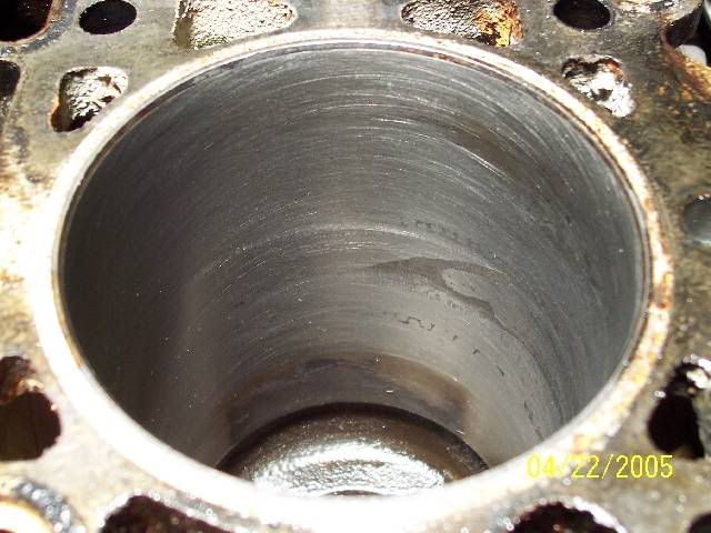
But none of that even matters at all now. Not one bit. I went to hone all of my cylinders in preparation for new rings when I discovered that some of the darkness in the bores is really areas where the bore corroded from water in the cylinders! I knew there was some darkening of the cylinder wall, but figured that it'd be gone after I deglazed it. Nope. Check it out:
Suckage. Now THAT is not a pretty sight. That's after I wailed on it with a deglazer, trying to make it go away. To get rid of it, I'll have to go with a rebore. This will mean new pistons, which is going to be expensive. I must now rebuild the shortblock as well. The costs are adding up, but it means that I'm now going to pay to educate myself on what it's like to rebuild a motor. That's the way I see it, as there is no stopping me now that I've come this far.
Now I ask for help:
- Has anybody rebuilt one of these things and know roughly what it's going to cost to bore the cylinders oversize, press old pistons off and new pistons onto the rods? The machine shop is telling me 550-600 to do my heads already. I have a feeling that this is going to suck, though it will be possible.
- What are my options for pistons? Custom? What am I looking at, price wise? Recommendations? Now would be a nice time for one of those opinionated fights over which pistons are better and why... Can I bump my CR up to about 9.7:1 or so like the 96+ motors? Will this require premium gas? I'm looking to use 87 if I can since gas prices are insane here, but if the performance benefits are worth it, I will go higher. Will new pistons come with factory style ring grooves so I can use the rings I bought?
- Any suggestions on where I might pick up some exta power while I'm at it, or radical ideas?
[Edit]: To change image from HTML tag to UBB tag...
[This message has been edited by Blue Shift (edited 04-23-2005).]
- Any boring will require new pistons, yes? - As far as pistons go, what options do I have? I have a couple ideas (see below), but I'd like to know what's been done. - What does it cost to have a bore/hone done, ballpark? Is there anything else that would be a really good idea to have done as well?
I found that stocker pistons don't cost much (25-50 apiece depending on source), and I have a few questions about some specs I've found:
Sealed Power, for a 91 Olds Cutlass Supreme:
H813CP: 3.6220 EARLY or REPLACES LATE USED w/E548K RING SET
H684CP 3.6220 LATE or REPLACES EARLY USED w/E928K RING SET COMP :(1)1.20mm(1)1.50mm;OIL :(1)3.00mm COMP DIST:1.464";PIN DIA:.9054" DOMED HEAD .040" HIGH w/4 VALVE RELIEFS
I have a 91' motor from an automatic. What caught my eye is that the "early" piston has a '.040 dome'. Looking at the piston sitting in front of me, it looks dead flat except for 4 valve reliefs. Is Sealed Power # H813CP a Manual spec piston? Furthermore, the "Late" style piston has a compression height that is .006" higher than the early style piston, and also has a .040" dome. It says "replaces early" in there, if I change to the 1.20mm late style rings.
Big question: Can I slap in a set of oversize H684CP domed pistons for the 96' year engine into my 91' motor for a little more performance? Will I end up having to use 92 octane or even higher with a light cut taken from the heads, the extra compression height, and the dome? Will this work without nailing valves? Does the motor become interference if I do it? If I can't use later style pistons, are the H813CP early style pistons with a dome higher compression than stock automatic spec pistons? I ask these questions because I'm sure somebody has looked up replacement pistons and knows from experience whether this will work or not. I figure if I'm going to rebore/hone and get new pistons, that I might as well get a little more punch out of it. This is a performance motor, after all!
Secondary question: Not to sound like a broken record, or a n00b whiner about gas prices and stuff... but does anybody have a general idea at what compression ratio one would need 89 and then 92 octane gas? I don't have the faintest clue what these motors like to drink under various compression ratios and such.
[/snip]
[Edit] To disable smilies!
[This message has been edited by Blue Shift (edited 05-24-2005).]


 ) or is it fairly non-volatile that way? I'll be interested in how it works out. No primer; I assume it is MEANT to go on bare metal unlike the special rust coatings now. (3-5 components....)

 )
)