Pennock's Fiero Forum
  Technical Discussion & Questions
  1988 GT V6 engine compartment power distribution electrical connector removal

Post New Topic  Post A Reply
Email This Page to Someone! | Printable Version


next newest topic | next oldest topic
1988 GT V6 engine compartment power distribution electrical connector removal by mrv
Started on: 12-11-2025 07:01 PM
Replies: 6 (91 views)
Last post by: Raydar on 12-14-2025 02:56 PM
mrv
Junior Member
Posts: 2
From: Arizona
Registered: Nov 2025


Feedback score: N/A
Leave feedback

Rate this member

Report this Post12-11-2025 07:01 PM Click Here to See the Profile for mrvSend a Private Message to mrvEdit/Delete MessageReply w/QuoteDirect Link to This Post
Removing engine on, 1988 GT V6. Going by instructions on site. Question; on right side engine compartment next to battery, is an electrical connector (power distribution?) Has a long bolt through the electrical connector. Below it, are what appear to be two electical stud terminals. How to remove electrical connector in two pieces? Removed electrical connector appears molded in one piece. Rear wires in connector go to engine, front wires travel to body. How to remove the connector on the engine side, without going wire by wire out of electrical connector? I have the connector unplugged. I read a passing post by someone, to cut the electrical connector in two pieces? What to do? It would be nice to just unplug and place harness on top of engine. I am stuck until resolved. Thanks in advance. In Arizona
IP: Logged
PFF
System Bot
Raydar
Member
Posts: 41588
From: Carrollton GA. Out in the... country.
Registered: Oct 1999


Feedback score:    (13)
Leave feedback


Total ratings: 463
Rate this member

Report this Post12-11-2025 08:43 PM Click Here to See the Profile for RaydarSend a Private Message to RaydarEdit/Delete MessageReply w/QuoteDirect Link to This Post
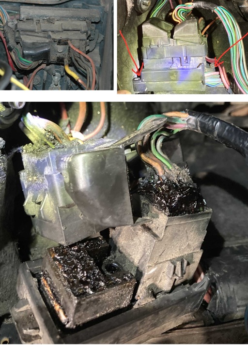
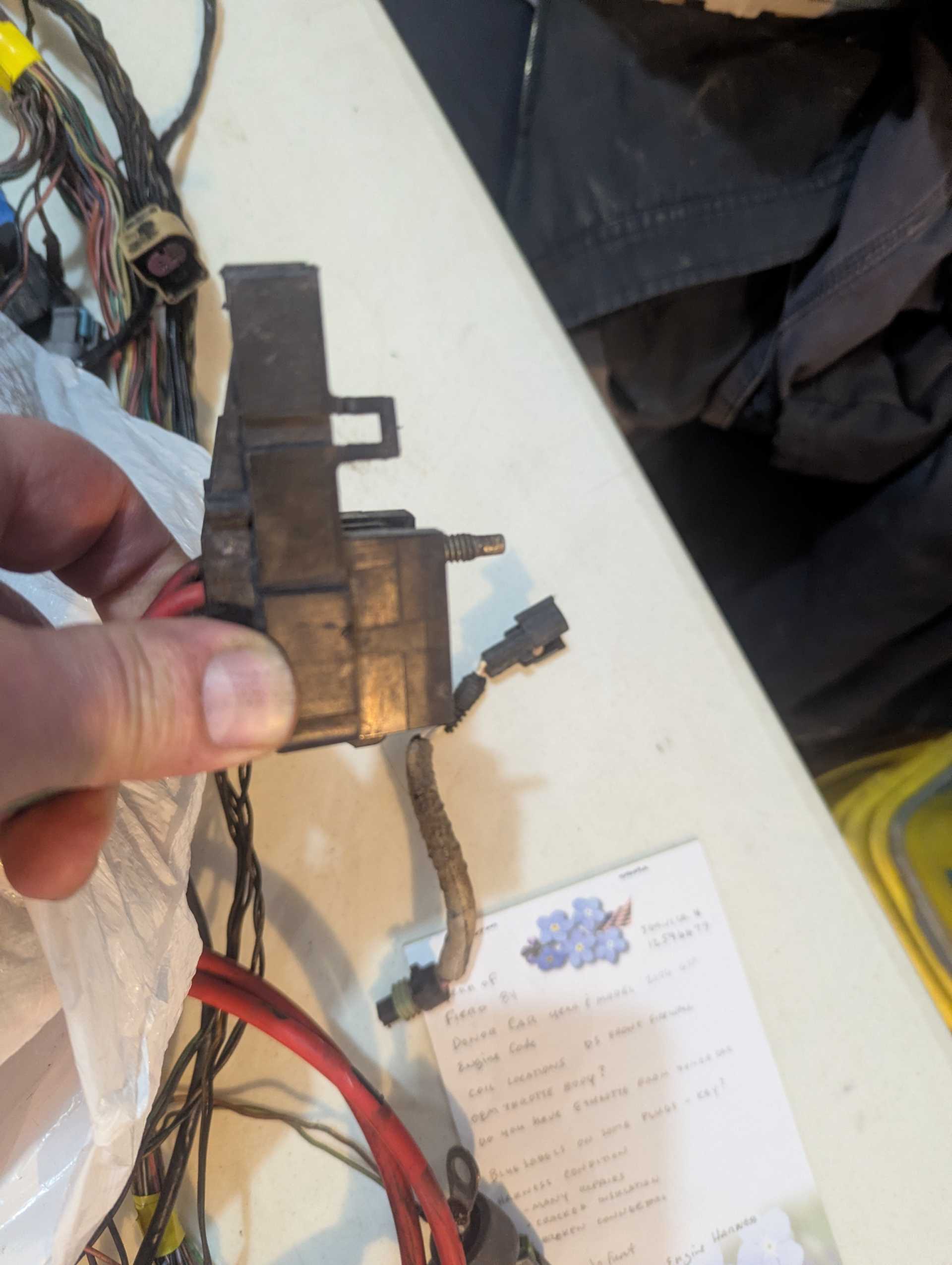
That connector is "C-500".
The connector that you unplugged/removed is indeed in two pieces. One half for the engine wiring, and one for the body wiring.
One half has a "frame" attached to it, that wraps around the outside edge of the other half. There may be a lug that the bolt goes through, too. You should be able to push or pull the two halves apart, without too much trouble. It's been a while since I did this, so I'm not clear on which half does what, but there are two pieces, not including the base which is attached to the car.

Also, when you get around to removing the red wires from the lugs, you will discover that those nuts are SAE. Not metric, like most everything else on the car.

Good luck with your endeavors, and welcome to our obsession - and the madness.

Edit - Check this thread.
https://www.fiero.nl/forum/Forum2/HTML/146677.html
There's a pic of the "engine half" of the C500 connector, as well as C203 (at the back of the center tunnel, under the ECM.)
This was for an aftermarket application, but you can at least see what the connectors look like, unplugged.

------------------
Raydar
88 Formula IMSA Fastback. 4.9, NVG T550

Praise the Lowered!

[This message has been edited by Raydar (edited 12-11-2025).]

IP: Logged
mrv
Junior Member
Posts: 2
From: Arizona
Registered: Nov 2025


Feedback score: N/A
Leave feedback

Rate this member

Report this Post12-11-2025 10:04 PM Click Here to See the Profile for mrvSend a Private Message to mrvEdit/Delete MessageReply w/QuoteDirect Link to This Post
Thank you for the knowledgeable quick reply. Just went back to the shop. Electrical connector is in two parts. Problem, flange bolt?screw, holds both electrical connectors together. How to remove flange bolt? Tried unscrewing and pulling. Also pressure on end and then rotating. Is there a pin or lock device retaining the flange head small bolt in the electrical connectors? No doubt more questions as this continues. Looks like no one has been into the car before. Thank you in advance for the advice and help. Now for that flange bolt, to seperate the electrical connectors.
IP: Logged
Vintage-Nut
Member
Posts: 1977
From: Non-Normal California
Registered: Apr 2020


Feedback score: N/A
Leave feedback

Rate this member

Report this Post12-11-2025 10:49 PM Click Here to See the Profile for Vintage-NutSend a Private Message to Vintage-NutEdit/Delete MessageReply w/QuoteDirect Link to This Post
I found a few images of the C500 which may help...


quote
Paul Prince:
C500 is held in by a 1/4" (head) bolt, unscrew the bolt / then separate the two sides

------------------
Original Owner of a Silver '88 GT
Under 'Production Refurbishment' @ 136k Miles

[This message has been edited by Vintage-Nut (edited 12-11-2025).]

IP: Logged
olejoedad
Member
Posts: 20083
From: Back home again in Indiana
Registered: May 2004


Feedback score: (5)
Leave feedback


Total ratings: 201
Rate this member

Report this Post12-12-2025 08:31 AM Click Here to See the Profile for olejoedadSend a Private Message to olejoedadEdit/Delete MessageReply w/QuoteDirect Link to This Post
The front part (tail light harness) pushes through the frame that surrounds the plug. There are two catches on the surrounding bracket the bolt is captive in the engine part of the connector.
IP: Logged
olejoedad
Member
Posts: 20083
From: Back home again in Indiana
Registered: May 2004


Feedback score: (5)
Leave feedback


Total ratings: 201
Rate this member

Report this Post12-12-2025 08:41 AM Click Here to See the Profile for olejoedadSend a Private Message to olejoedadEdit/Delete MessageReply w/QuoteDirect Link to This Post

olejoedad

20083 posts
Member since May 2004


This is a side view of the C500 connector, showing a retaining clip and the captured bolt.
After releasing the clips on either side, push the small taillight plug through the bracket to separate the two parts off the connector.
IP: Logged
Raydar
Member
Posts: 41588
From: Carrollton GA. Out in the... country.
Registered: Oct 1999


Feedback score:    (13)
Leave feedback


Total ratings: 463
Rate this member

Report this Post12-14-2025 02:56 PM Click Here to See the Profile for RaydarSend a Private Message to RaydarEdit/Delete MessageReply w/QuoteDirect Link to This Post
Thanks Joe. I didn't have any pics handy, and it's been a while since I've taken that connector apart.
IP: Logged

next newest topic | next oldest topic

All times are ET (US)

Post New Topic  Post A Reply
Hop to:

Contact Us | Back To Main Page

Advertizing on PFF | Fiero Parts Vendors
PFF Merchandise | Fiero Gallery
Real-Time Chat | Fiero Related Auctions on eBay


Copyright (c) 1999, C. Pennock