Countless members had been dealing with cracked console frames by ‘gluing’ the plastic pieces back or other methods for a long, long time….
In 2022, member
mmeyer86gt/gtp posted a 3D Printed Skeleton product listed in ‘The Mall’ and the five-piece set was $240 plus shipping:
https://www.fiero.nl/forum/Forum4/HTML/079946.htmlHowever, the last post in the thread was 2023, so in 2025 I inquired the current price for the kit...
Alas,
mmeyer86gt/gtp informed me that he now sells the standard sets to ‘The Fiero Store’ though he is still agreeable to making custom kits on PFF.
Consequently, I ordered the five-piece set through TFS early on a Monday.
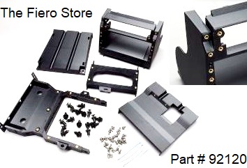
TFS printed the shipping label the same day; UPS picked-up the package on Tuesday and I got it on the next Monday.
The parts were bubble-wrapped and as I unpacked the kit, of course I noticed the improved machine screws into brass inserts, plus the ABS plastic was thicker/stronger than the OEM frame.
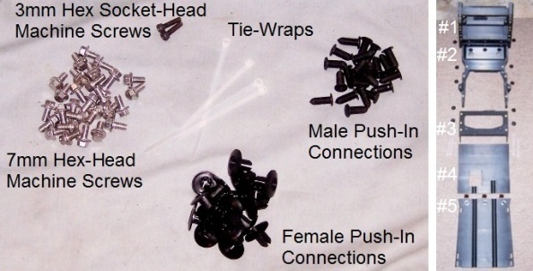
The kit also included a bag of hardware devoid of any printed materials:
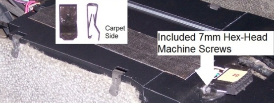
29) Stainless-Steel 7mm hex-head machine screws {M5-0.8x10mm} with 2 extras
2) Black Oxide Steel 3mm hex socket-head machine screws {M4-0.7x15mm}
18) Plastic female push-in connections {2 extras}
23) Plastic male push-in connections {7 extras}
5) 4-inch tie-wraps {1 extra}
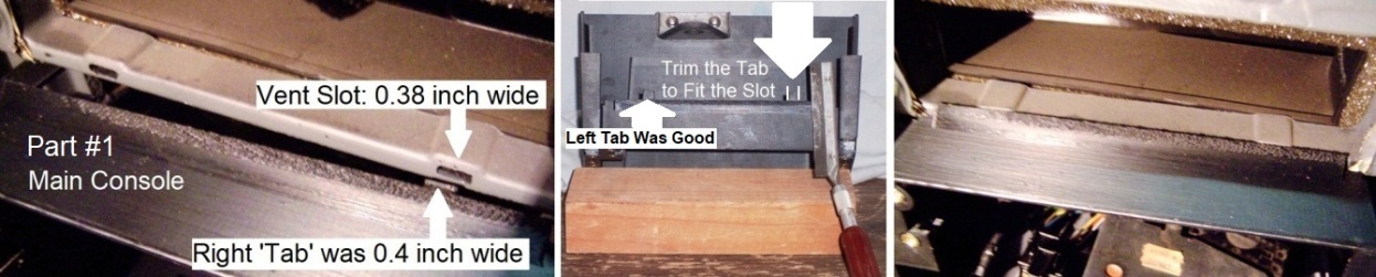
 Trial Run Prior AssemblingPart #1: Main Console
I noticed that the main console piece didn’t have any holes for the rear support of the factory radio/tape unit.
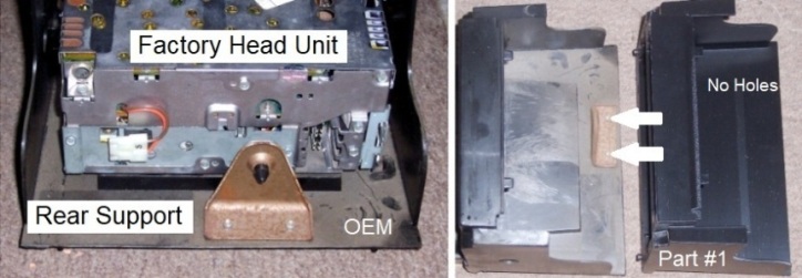
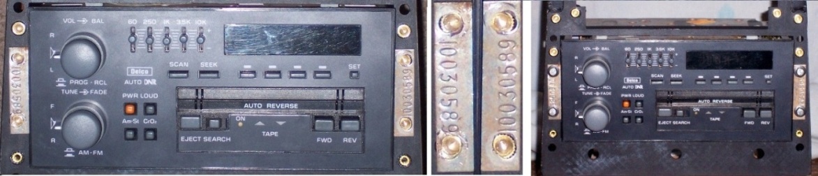
I know that many members ‘ditch’ the 1980’s OEM head unit; however, I got the original Delco unit serviced.
Thus, the next move for me was to install the head unit into the new console so I can position ‘where’ I need to drill and fasten the rear support.
Issue #1The Delco rack mounting ear holes didn’t align with the new console brass inserts.
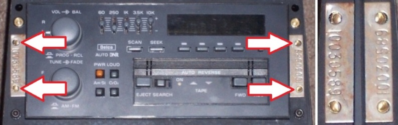
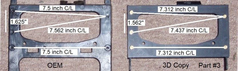
Measuring the OEM to the new 3D copy, four brass insert locations were off.
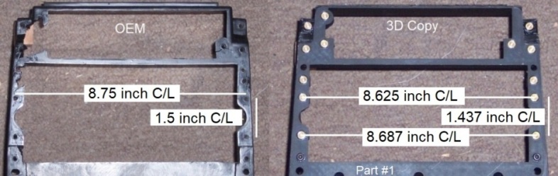
The only option was to file the rack ear holes to match with the brass insert locations. Once done; the issue was solved.
With the radio installed in the console, I mounted the rear support, drilled the holes and then fastened it with M4 screws, washers and flange nuts.
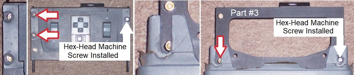
I verified the brass insert locations with the six holes of the console-to-vent support plate and they fitted nicely. The two included M4-0.7 machine screws mates with the smaller brass inserts to hold the bottom of the main Vent/HVAC/Radio trim panel, although you’ll need to use your hardware on the top.
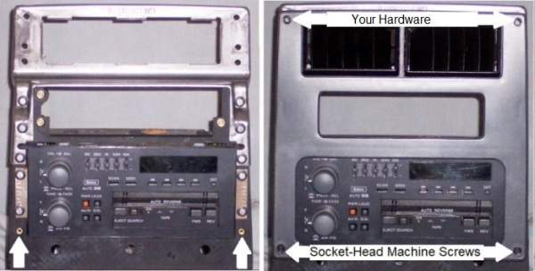
These new machine screws in the bottom are socket-heads while the factory used Torx head screws.
*Picky me wants four screws in the same ‘type’ so I’ll search to see if I can locate either/or….The last insert locations to check in the main console part were the climate control unit mounting holes…
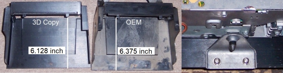
*SIDEBAR: R&R of the Climate Control Unit*IMHO: Removal and reinstallation of the unit aren’t ‘easy’ tasks, and I make a decision to circumvent this irritating difficulty…
The center plastic ‘bar’ which divides the HVAC and the radio openings was cracked on the OEM console. This allowed me to pull the factory skeleton out without disconnecting the unit.
To install the new 3D console, I choose to cut-out the center support, leaving one larger opening which allows the unit in/out without reconnecting or disconnecting it.
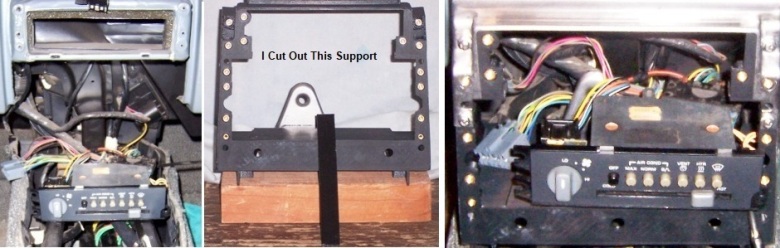
In my assessment, this beneficial feature is more valuable than having the extra strength.
*End of Sidebar*Issue #2When I attempted to install the main console to the vent opening, the right console ‘tab’ was too large to fully insert into the slot. The tab was 0.4 inch wide while the vent slot was 0.38 inch wide. I trimmed the tab to fit the slot which solved the issue.
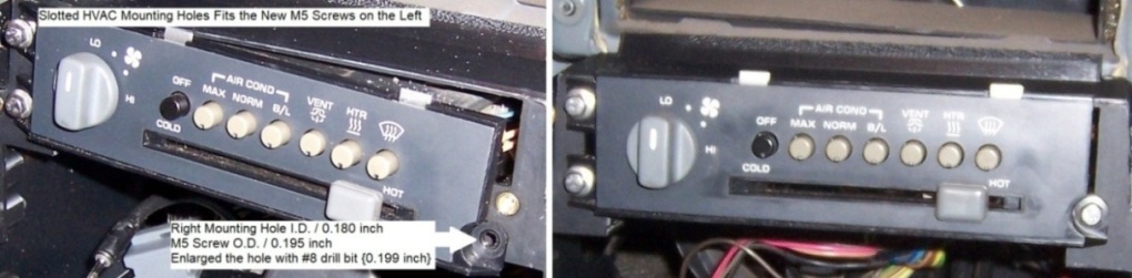
Going back of verifying the HVAC mounting screw holes with the main console brass inserts…
Issue #3 The left HVAC mounting screw holes are slotted and the M5 screws fit; however, the right mounting hole was too small for the new screw. Using #8 drill bit {0.199 inch} and enlarging the hole solved the issue.
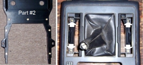
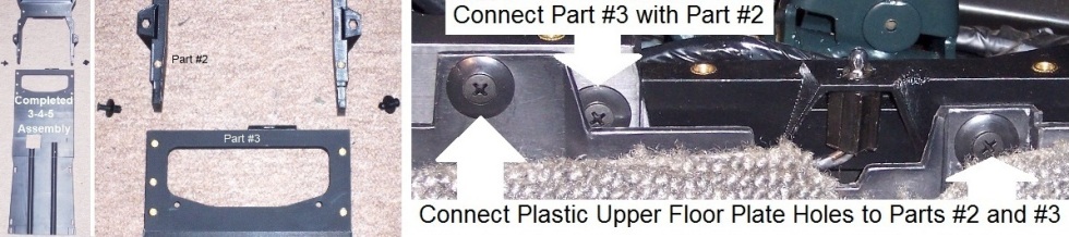
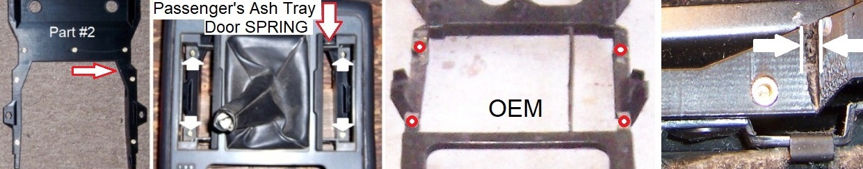
 Part #2: Main Console Pad / Shift Plate
The three lower main console pad holes aligned correctly, but the four holes in the ash tray area of the shift plate didn’t. The OEM frame measured around the same; so perhaps my shift plate assembly might be distorted, and I will deal with it later...
 Part #3: Shifter Trim and Rear Console PadIssue #4
Using the right-hand round mounting hole of the shifter trim, the left-hand slotted holes didn’t align with the brass inserts.
Same on the rear console pad; the mounting slots didn’t align either.
Measuring the OEM to the new 3D copy, five brass insert locations were off…
The only way out is to enlarge the slots to bring them into line with the inserts and add fender washers for more support.
 Part #4: Assembly Line Diagnostic Link
 The ALDL connecter mounting holes aligned with the brass inserts and this is the end of the trial run.
Some Assembly RequiredI presume an individual
might build this five-piece skeleton as one frame like the OEM, and then install the completed unit in the vehicle.

However, in my review, I preferred an ‘easier’ method by installing Part #1; then Part #2 and followed up with the last three parts as an assembly.
The
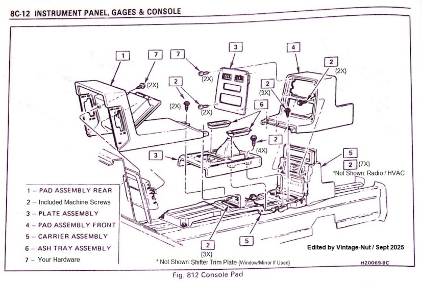
Pontiac Fiero Service Manual has a center console section and I edited this GM illustration for my technique as a guide.
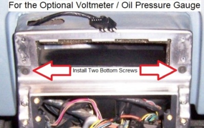
{Please note that the illustration shows the ‘standard’ version lacking the optional voltmeter and oil pressure gauge}
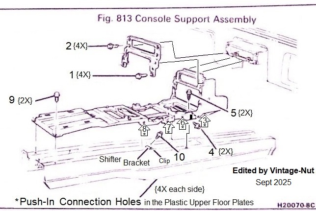
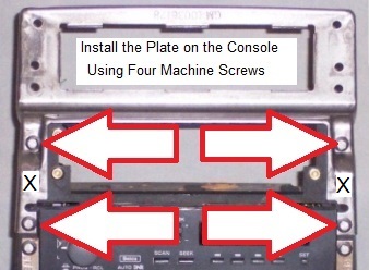
Start with Part #1 and install the console-to-vent support plate with four of the included 7mm hex-head machine screws. {1 in GM illustration}
Align the main console tabs into the vent slots of the dash and install your hardware to hold the plate in place. {2 in GM illustration}
*For the optional voltmeter / oil pressure gauge; install only the bottom two screws instead of the four shown in the GM illustration.
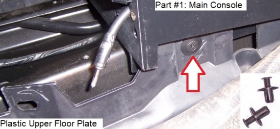
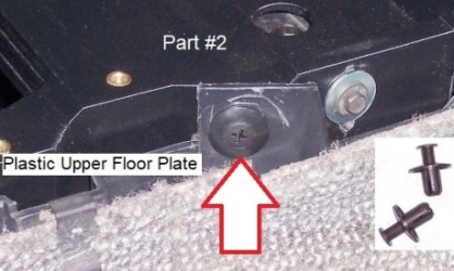
Align the bottom holes of Part #1 with the plastic upper floor plate holes and then secure them with two of the included plastic M/F push-in connections. {3 in GM illustration}
Remove the tunnel bracket from the vehicle if it is not removed already.
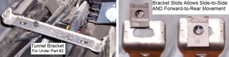
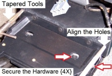
Loosely install the tunnel bracket beneath of Part #2 with your hardware. {4 in GM illustration}
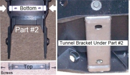
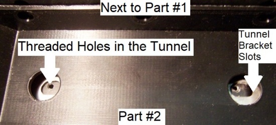
Position Part #2 on the tunnel and next to Part #1, and then verify that the tunnel bracket slots beneath of Part #2 line up to the tunnel threaded holes.
 *Special Note 1*
When I removed my tunnel bracket from the tunnel, the side-to-side slots were maxed rearward, and the forward-to-rear slots were
also maxed to the rear.
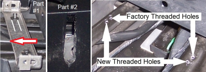
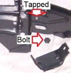
Alas, I didn’t get the factory threaded tunnel holes to line up with the bracket when installed below Part #2.
I ended-up drilling and threading new holes to align correctly with the new part.
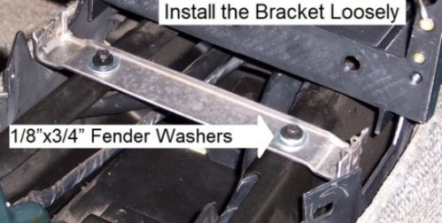
Remove Part #2 from the vehicle; remove the tunnel bracket from beneath and then reinstall the bracket
loosely on the tunnel using your hardware. {5 in GM illustration}
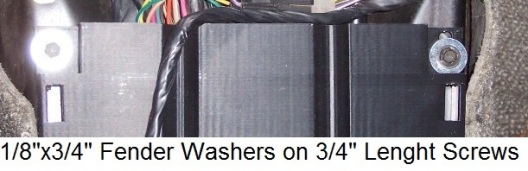
*I added 1/8”x3/4” fender washers on the screws as the bracket slots were wider than the factory hardware.
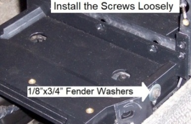
Install Part #2 on top of the tunnel bracket, and then
loosely install your hardware through the slots and into the bracket. {4 in GM illustration}
*Again, I added 1/8”x3/4” fender washers on the factory screws for more support.
Align the plastic upper floor plate holes with Part #2 and secure them using two of the included plastic M/F push-in connections. {6 in GM illustration}
Align the three holes in Part #2 with Part #1 and then secure them with three of the included plastic M/F push-in connections.
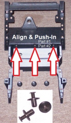
Align the main console pad pin holes in Part #2 and Part #1
{I used tapered tools to align and hold the holes} and then secure the tunnel bracket hardware. {4 and 5 in GM illustration}
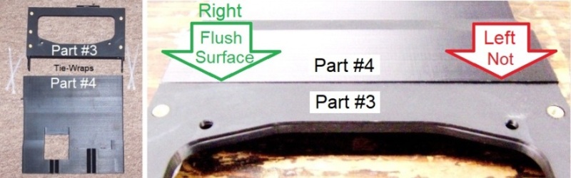
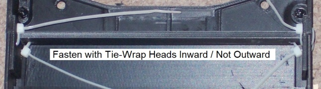
On a work surface, Part #3 gets connected to Part #4 with the included tie-wraps through slots of both parts.
However, the left side on my assembly didn’t align properly.
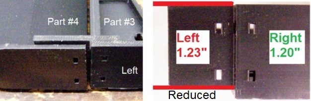
 Issue #5
The right ‘tab’ on Part #3 measured 1.20 inch; the left ‘tab’ measured 1.23 inch.
By removing 0.03 inch off of the top of the left tab; the align problem was solved.
When fastening the tie-wraps through Parts #3 and #4; observe that the tie-wrap heads are better inside to make the outside surface flusher.
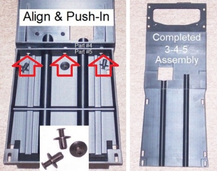
Align the three holes in Part #4 with Part # 5, and then secure them with three of the included plastic M/F push-in connections.
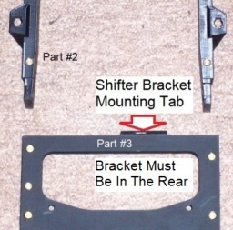
Position the completed 3-4-5 assembly on the tunnel with Part #3 facing and abutting of Part #2 making sure that your shifter bracket is adjacent to the back of the mounting ‘tab’ of Part #3.
*If not; gently ‘bend’ the bracket as needed.
 *Special Note 2*
When ‘tweaking’ my manual shifter bracket, I discovered a GM design error which is also on the 3D Copy.
Fiero shifter brackets have ‘raised edges’ around the threaded clip, which the plastic frame must lay flat on the clip.
Note that the raised edges on the manual are elevated more than the automatic edges and these brackets were riveted on the shifter bases.
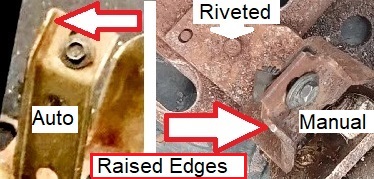
The GM design
attempted to mitigate these raised edges at the console frame; though the difference of the two planes is ~0.05-inch apart, while the manual edges are ~0.2-inch high.
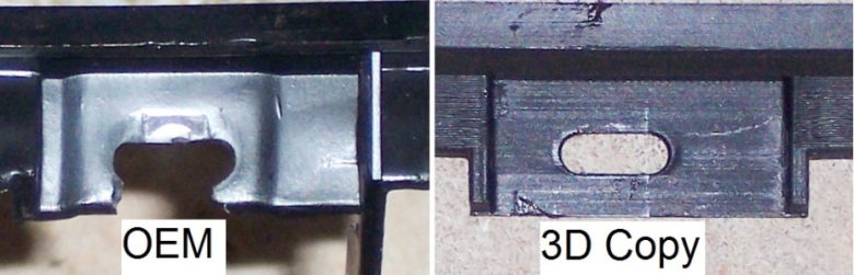
Conversely, the back of the 3D Copy has one flat surface.
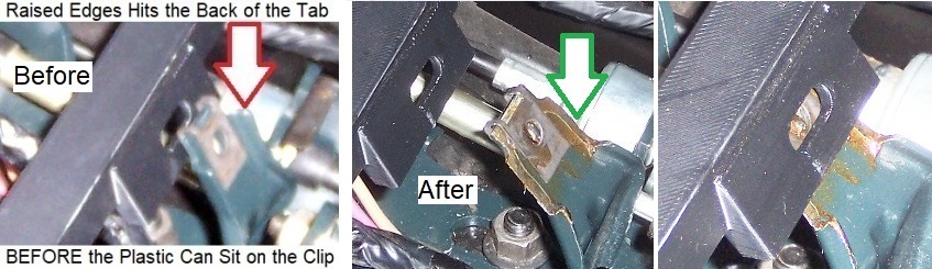
 As a result
, these raised edges on the auto/manual brackets contacts the back of the mounting area in Part #3 BEFORE the plastic can meet on the shifter bracket clip. With an empty space between the plastic and clip; the mounting screw is capable to distort the plastic or break the tab when securing the hardware.
To eliminate this void, a spacer {i.e. washers} is needed between the plastic and the clip OR completely removed the raised edges around the connection. I decided the latter as my recent shifter assembly rebuilt made removing the bracket simple.
Hence, I removed the shifter bracket from the base; put it in a vise and then filed off the raised edges. With these edges gone, the back of Part #3 can now lay flat on the bracket clip. Later, the joint can be secured tightly without cracking the new skeleton.
 IF you leave this situation ‘as-is’
, my suggestion is leaving out the screw OR least don’t tighten the hardware too much as your new plastic frame might break at this spot.
*End of Special Note 2*With the completed 3-4-5 assembly still sitting flat on the tunnel and abutting of Part #2; verify that the tunnel threaded holes beneath the slots of Part #5 lines up.
*My didn’t and needed to drill and thread new holes in the tunnel to align correctly with the slots of Part #5.
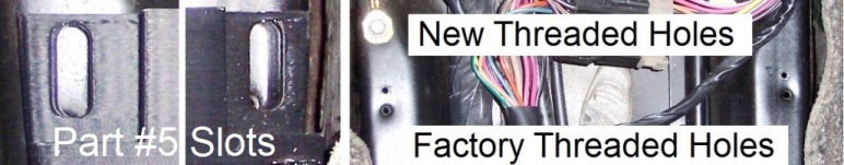
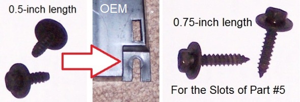
Also note that the rear of the factory console support used 0.5-inch length screws while Part #5 has deeper slots to mount on the tunnel. Made sure your extra 0.75-inch length screws will mate with the tunnel threads.
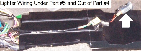
Route the lighter wiring harness under Part #5 and through the opening in Part #4.
Mount the wiring harnesses of the ash tray lighting into the holes under the Part #3, and then to the outbound side of Part #2
between the plastic upper floor plate, next carefully twist the sockets into the mounting holes as the plastic twist-lock ‘tabs’ are small and very old…
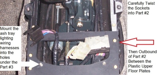
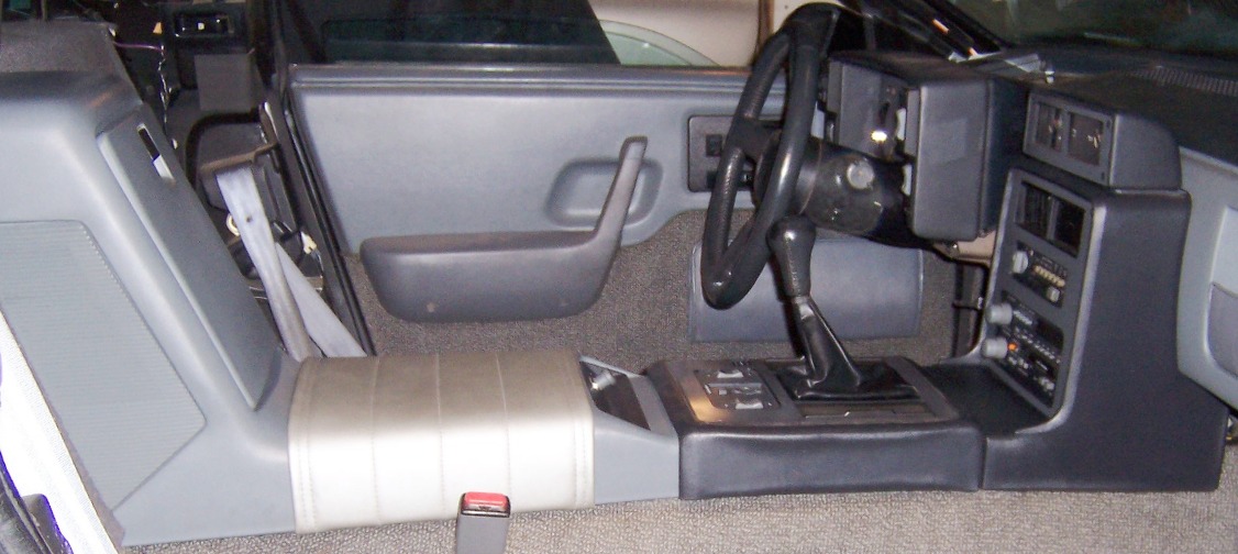
Route the power window/mirror wiring connecters {if used} to the center of Part #3 as shown in the last photo.
Align and connect Part #3 with Part #2 with two of the included plastic M/F push-in connections. Afterward, align the last plastic upper floor plate holes to Parts #2 and #3 and secure them with four of the included plastic M/F push-in connections. {7 and 8 in GM illustration}
Install your 0.75-inch screws through the rear slots of Part #5 and tighten them on the tunnel. {9 in GM illustration}
*I added 1/8”x3/4” fender washers on the factory screws for more support.
Install your hardware through the slot of the mounting ‘tab’ of Part #3 into the shifter bracket clip and secure the joint. {10 in GM illustration}
*I added a 1/8”x3/4” fender washer on the factory screw for more support.
Install the four carpet clips on the rear slots of Part #5.
Mount the ALDL connecter on Part #4 using two of the included 7mm hex-head machine screws.
 The new center console skeleton/support/frame is complete!
 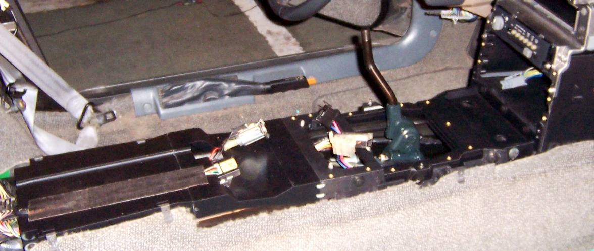 Put Your ‘Stuff’ Back
Reinstall the rear pad; lighter and trim plate; radio; climate control unit; front pad; front trim panel; shifter trim plate and shifter plate using the edited GM illustration below and your manual.
 Summing It Up
The 3D reproduction of the center console frame wasn’t plug-and-play, though this review is a single kit which I received from ‘The Fiero Store’.
Noticeably, the main issue of the kit was the inaccurate positions of some brass inserts. The few issues listed required ‘carving’ factory items to alter them on the new skeleton.
As a retired manufacturing engineer, I was not pleased about the situation with any other option than the chances that TFS might have a ‘better’ replacement;
which I didn’t make an effort.
I also did not attempt to have a discussion with the creator; as my experience taught me that when sharing positive criticism,
very often I got a negative reaction.
On the bright side and taken as a whole, I’m
very satisfied with the end result! The product
IS superior to the OEM frame with the coarse-thread screw method.
If you’re still on the fence, the kit is highly recommended if your factory console support is falling apart..
If you’re planning to change the factory head unit size, don’t order the ‘standard’ kit from TFS; double-DIN or other custom kits are available on PFF at the link above.
Hopefully, this review might help…
----------------------------------------------------
Addendum {After-the-Fact}
In the original post above, I commented on a few issues in the “Trial Run Prior Assembling” section that “I will deal with it later” meaning when these factory items are reinstalled on the mounted console skeleton in the vehicle.
However, I didn’t engage with these issues in the “Put Your ‘Stuff’ Back” section,
until now…This section is to ‘close the loop’ on these issues and to report two new issues I discovered while reinstall these factory items on the console skeleton.
Shifter TrimAll three mounting slots/hole needed slight ‘carving’ to align with the brass inserts on the mounted console skeleton. I used the console skeleton sides to center the Shifter Trim, and then modified the holes as needed. Sorry, no photo…
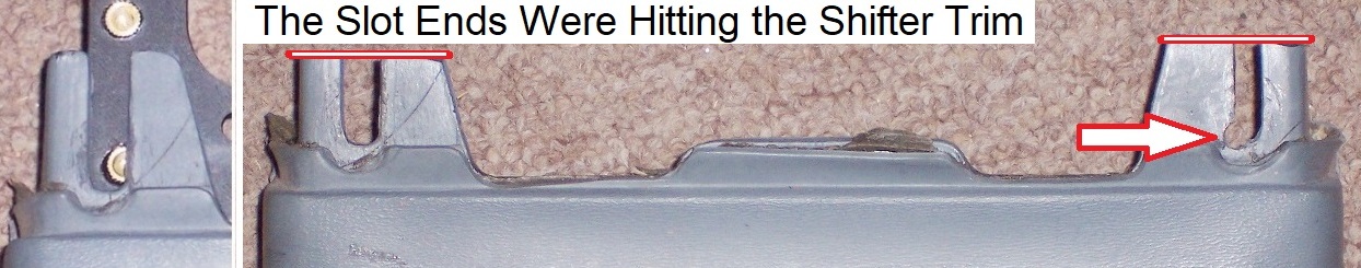
Rear Console PadCentering the Rear Console Pad on the console skeleton; the left mounting slot was correct; the right side was slightly off and needed some carving. In addition, the ends of the mounting slots were too long and hitting the Shifter Trim. The photo shows the ‘carving’ and cutting the slot ends to fit with the Shifter Trim.
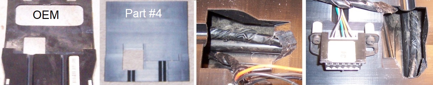
With Rear Console Pad mounted on the frame, the lighter didn’t fit into the rear console pad mounting area as the lighter was hitting Part #4 of the skeleton. The ground connection on the bottom of the lighter needed a lot more clearance. The OEM frame was thinner at this area; the new skeleton is thicker. I attempted to carve a round ‘divot’ but the skeleton needed major cutting to the lighter fit into the rear console pad.
As a Note: ALDL connecter was ‘buried’ into the rear pad; I used standoffs and longer hardware, so the connecter was easier-to-use.
 Shifter Plate
The four holes in the ash tray area of the shift plate needed slight carving to align to the brass inserts. I used the front console pad sides; centered the shifter plate, and then modified the holes as needed.
With the Shifter Plate aligned, the passenger’s ash tray door started to close when tightening the hardware; the door spring was hitting Part #2 of the skeleton. This area on the factory frame had the clearance for the spring, however Part #2 is wider/beefier than the OEM. This photo shows the clearance ‘groove’ needed for the spring to modify the skeleton.
NOW, I'm
Really Done with the Console Skeleton!

------------------
Original Owner of a Silver '88 GT
Under 'Production Refurbishment' @ 136k Miles
[This message has been edited by Vintage-Nut (edited 11-17-2025).]


