I started acquiring bits and bobs to add a digital cruise control module to my 1985 4cyl Fiero, but have run into the predictable snag of acquiring a suitable 4000 PPM signal for the cruise module. I understand that the VSS outputs a variable-voltage sine-wave 4000 PPM signal, which goes to the speedometer control board for a divide by 2 and square-wave buffered into 2000 PPM for the ECM and old vacuum cruise servo control module. I have found references to people modifying the 86-87 boards to add a buffered 4000 PPM output, but haven't found anything on the 1985-older boards.
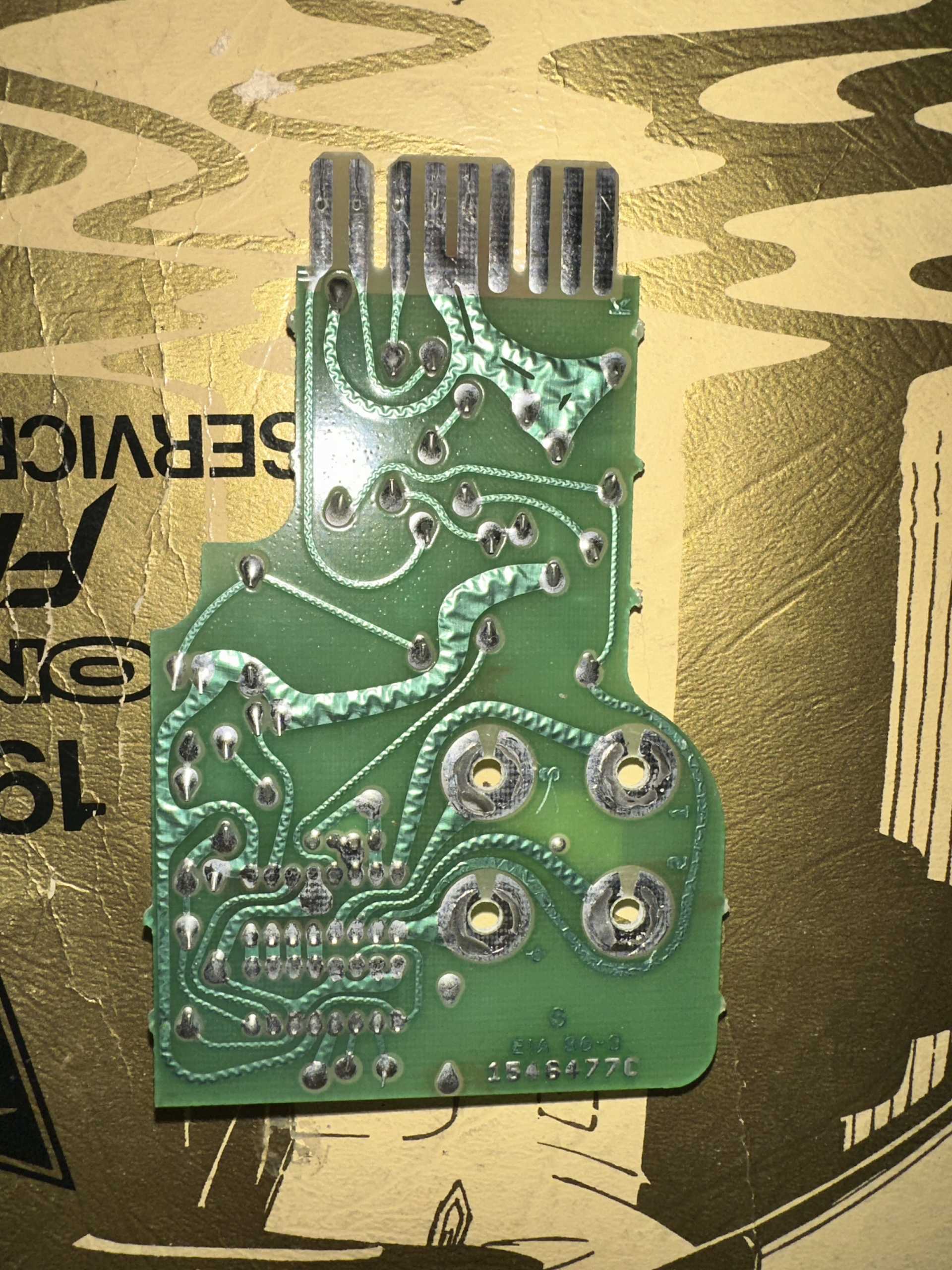
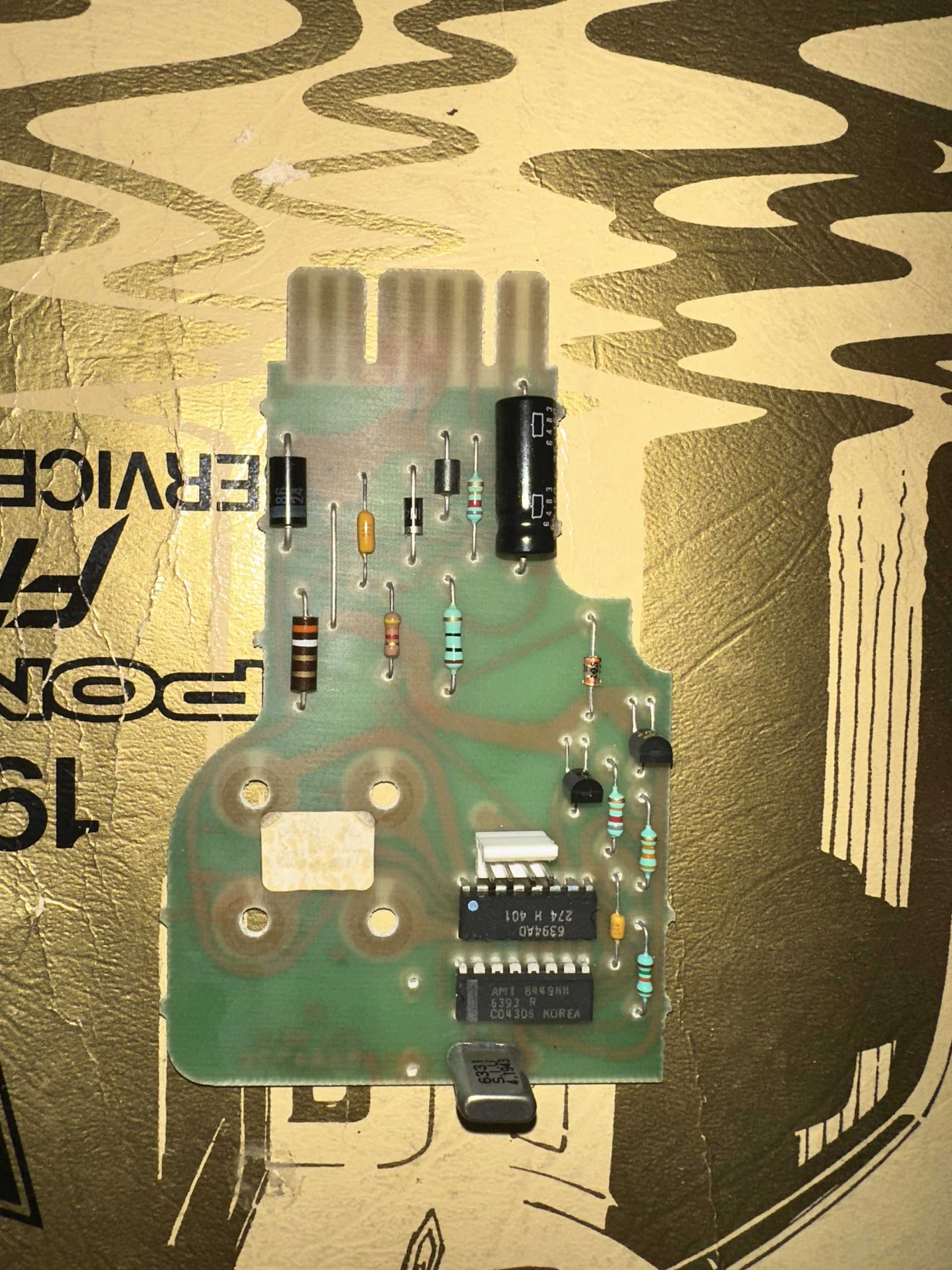
It appears that the circuit design is similar, but clearly different; The board (P/N 1546477C) layout itself is clearly hand-drawn, and connections between the two DIP-16 packages seem similar to the 86+ boards. I unfortunately can't find any information on the two ICs on the board, labeled "AMI 8449HH - 6393 R - C04306" and "6394AD - 274 H 401". The AMI chip has a 4.1943 MHz? kHz? Crystal feeding into it, and appears to drive the 2000 PPM output through an NPN transistor to ground and a FET? to one of the 6494 pins. The VSS input is to the 6494 IC, and there are what seems to be 5 signal interconnections between the ICs, only one of which isn't short pin-to-adjascent-pin. The 6494 chip also outputs the signals for the speedo gauge as well as the trip/odo motors.
If anyone has any info on these chips, or any info about this generation of speedo control boards, I would greatly appreciate you sharing!
The VSS sign wave signal is sent to a buffer that is located on the speedometer board for the 85-86 Fieros. In short the buffer is on the speedometer board and it should provide a reference signal for the speedometer itself and the CC. What is it about the output signal that you now have that that cannot be used?
------------------ " THE BLACK PARALYZER" -87GT 3800SC Series III engine, custom ZZP /Frozen Boost Intercooler setup, 3.4" Pulley, Northstar TB, LS1 MAF, 3" Spintech/Hedman Exhaust, P-log Manifold, Autolite 104's, MSD wires, Custom CAI, 4T65eHD w. custom axles, Champion Radiator, S10 Brake Booster, HP Tuners VCM Suite. "THE COLUSSUS" 87GT - ALL OUT 3.4L Turbocharged engine, Garrett Hybrid Turbo, MSD ign., modified TH125H " ON THE LOOSE WITHOUT THE JUICE "
I assume that there is a buffered 4000 ppm signal somewhere on-board before it gets divided, but reversing-engineering what is happening without any clue what these ICs are is difficult.. The digital cruise module I have expects to see 4000 ppm, the stock speedo board outputs 2000. I know I could wire in a DRAC to buffer the 4k signal from the vss before the speedo for the cruise module, but I'd rather not modify the harness to add one, nor spend the money to purchase one.
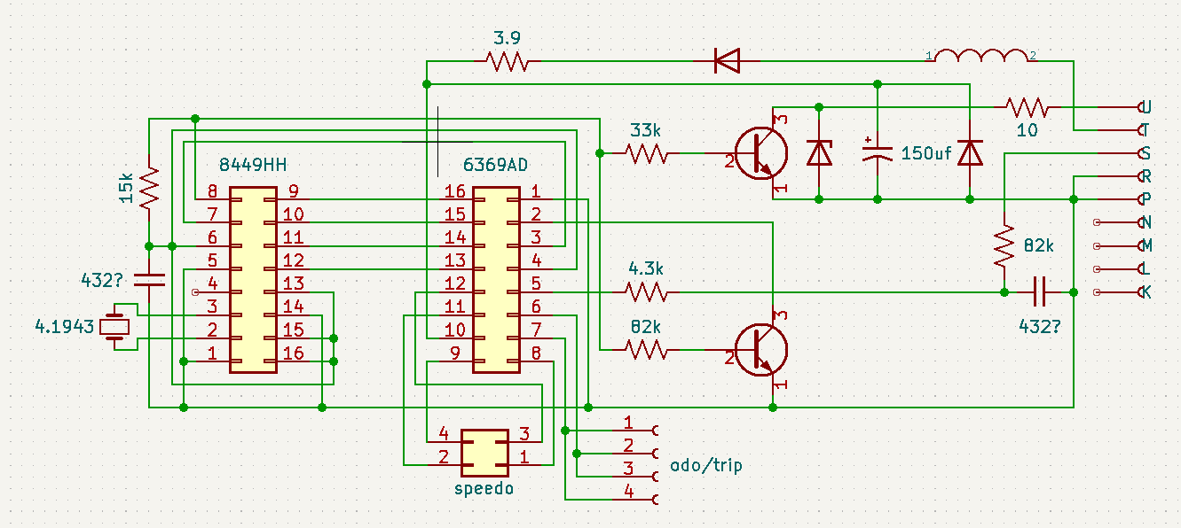
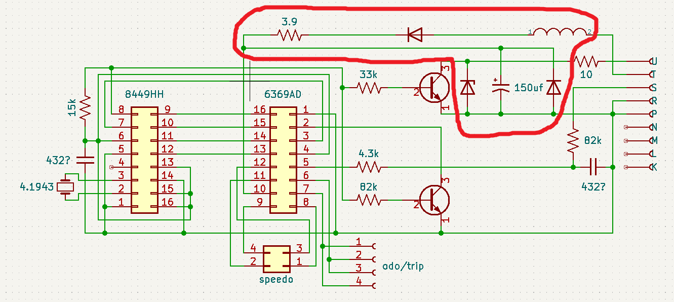
I went ahead and put together a schematic for the board off of my speedo.. I think it is accurate, but am unsure on a couple of the components, namely the ceramic/tantalum capacitor values, and the zener diode- It is small glass package without a polarization marking- And finally the lower transistor, which may be a FET of some kind.. Searching the part number didn't yield anything.
Take the signal directly off of the VSS sending unit and build a conversion circuit found on gmtumers.com (Sinister Performance - Tech Section - Wiring Diagrams)
A couple of resistors, a capacitor, a diode and you've got the 4000 ppm squarewave signal you need.
EDIT!
The erroneous post above has been edited to prevent confusion.
Evidently, I'm confused enough!
[This message has been edited by olejoedad (edited 08-25-2025).]
"Installing a digital cruise in the Fiero" by Oliver Scholz
Perfect. Oliver Scholz is the name I was also thinking of. He has done all sorts of Fiero electronics. I think he is also in several of the Farcebook Fiero groups, if you want to contact him directly.
Take the signal directly off of the VSS sending unit and build a conversion circuit found on gmtumers.com (Sinister Performance - Tech Section - Wiring Diagrams)
A couple of resistors, a capacitor, a diode and you've got the 4000 ppm squarewave signal you need.
Is there any way you can direct-link the article you are referencing? I am unable to visit the site you mention (I tried gmtuners, in addition to gmtumers, no site found.)
quote
Originally posted by Spadesluck:
Take a look at this article about adding a digital cruise to the Fiero. It tells you exactly where the 4000ppm signal is at on the speedometer.
This was my original plan, but this article only applies to 86+ boards. Mine is different in that it doesn't seem to have the "CS8524" chip onboard. See pics below
quote
Originally posted by Raydar:
"Installing a digital cruise in the Fiero" by Oliver Scholz
Perfect. Oliver Scholz is the name I was also thinking of. He has done all sorts of Fiero electronics. I think he is also in several of the Farcebook Fiero groups, if you want to contact him directly.
Any chance he has contact info outside of that site? Deleted my profile a few years back and won't touch the place anymore.
Take the signal directly off of the VSS sending unit and build a conversion circuit found on gmtumers.com (Sinister Performance - Tech Section - Wiring Diagrams)
A couple of resistors, a capacitor, a diode and you've got the 4000 ppm squarewave signal you need.
Can you provide a direct link to the article you're talking about?
I found one schematic on this page called "Fiero Speedo Conversion", but it is to convert from a square wave ECM or PCM output to a signal that can be understood by the Fiero speedometer. It is not to convert from a Fiero VSS to square wave. https://www.gmtuners.com/fiero/fmods.htm
The chip that has 4 wires connected to the gauge is obviously something special to drive the electromagnets in the gauge.
Your best bet is likely to power up the circuit with a VSS connected, spin it in a drill, and probe around with an oscilloscope. If you're lucky, you'll find the 4000 PPM somewhere.
Some key sections:
Is this KiCad? Thank you for adding to the forum with the schematic, even if it is imperfect.
If you can't find the 4000 PPM signal anywhere, for information, the 2000 PPM signal has a 50% duty cycle, so it has 4000 evenly spaced edges per mile. So you could generate a pulse for each edge (rising AND falling) and have 4000 PPM.
[This message has been edited by pmbrunelle (edited 08-25-2025).]
The chip that has 4 wires connected to the gauge is obviously something special to drive the electromagnets in the gauge.
Your best bet is likely to power up the circuit with a VSS connected, spin it in a drill, and probe around with an oscilloscope. If you're lucky, you'll find the 4000 PPM somewhere.
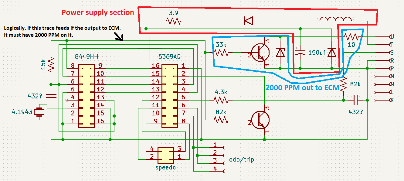
For information, this is the power supply section:
The resistor and zener diode form a shunt voltage regulator. The 150 uF capacitor forms a local power supply at the gauge. The non-zener diodes protect the gauge from damage in case the battery is connected with a reverse polarity.
Is this KiCad? Thank you for adding to the forum with the schematic, even if it is imperfect.
If you can't find the 4000 PPM signal anywhere, for information, the 2000 PPM signal has a 50% duty cycle, so it has 4000 evenly spaced edges per mile. So you could generate a pulse for each edge (rising AND falling) and have 4000 PPM.
I suspect that it's some sort of 3-coil/2-meter air core meter driver, and find it odd that there is so many parallel connections to the next chip over. It leads me to suspect that it is using some early adoption of SPI, but the tech era leads me to think that the other chip is too small to be an MCU.. But I am unsure. I do know for sure that the non-driver IC doesn't have a connection to the voltage rail feeding the meter driver for VCC, which implies a regulated supply in one of the parallel connections or a completely passive component.
Unfortunately I have reached a fairly similar conclusion in that I will need to probe around to find a signal. I'll have to go pull my oscilloscope out of storage and figure a way to drive the VSS input as I don't have a spare VSS to test with, and don't want to risk losing my gear to the bowels of my transmission. I might have to resort to testing in-vehicle with it up on jackstands.
I had identified (and poorly laid out) the input power supply section while looking over the layout, improperly identifying the lower right diode as not being a zener. I suspect that the inductor is for noise reduction and the resistor for overall current limiting. I do use KiCad, as it's free and runs well enough for my needs of circuit documentation; Good eye!
If I do end up going the route of an edge-detection-driven signal generator, I haven't been able to find out for sure if the GM digital cruise module (Marked "V8") expects a square or sine wave. I suspect square, as I've seen mention of the 4k signal being generated by the ECM in newer vehicles, and need to be conditioned into a sine to work the speedometer in the Fiero.
Originally posted by TGYK256: If I do end up going the route of an edge-detection-driven signal generator, I haven't been able to find out for sure if the GM digital cruise module (Marked "V8") expects a square or sine wave. I suspect square, as I've seen mention of the 4k signal being generated by the ECM in newer vehicles, and need to be conditioned into a sine to work the speedometer in the Fiero.
The Fiero was in the beginnings of fuel injection at GM, so it doesn't do some things the standard GM way.
In the Fiero, the VSS goes to the speedo board, which squares up the sine wave and sends it to the ECM.
In the more "standard GM" way, the VSS goes to the ECM, which squares it up, and then it provides an output to the instrument cluster.
The above circuit is a differentiator. I don't know if Sinister Performance himself developed this. No credit is given to any other author, so it must be him!
It generates voltage spikes on each square wave edge. The output is quite far away from being a sine wave, but the Fiero community has found that this circuit works to convert a square wave output into something (not sine) that can be correctly interpreted by the Fiero speedometer.
I was thinking backwards - we use that circuit to take the digital output from the 'normal' GM PCM's and make it something the Fiero speedo can live with.
Apologies!
I have edited my initial posting.
[This message has been edited by olejoedad (edited 08-25-2025).]
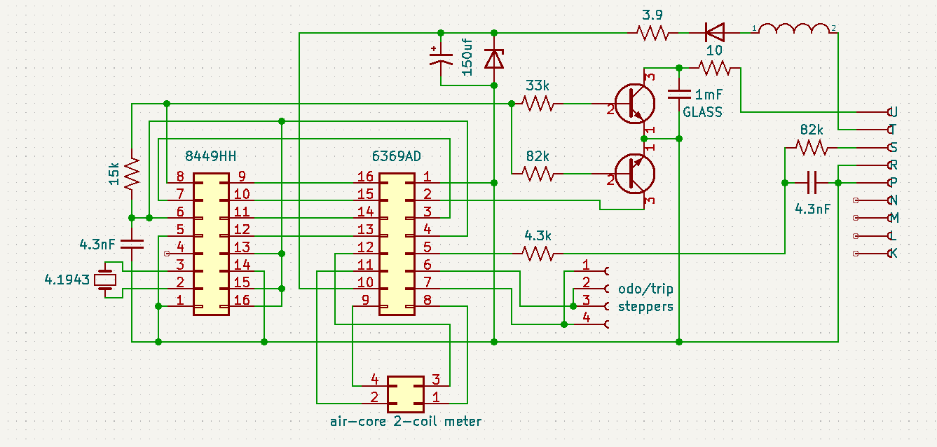
I heard back from Oliver over email (ty Spadesluck) and he did confirm to me that he believes there isn't a buffered 4000 ppm signal on these older boards, and that it seems the signal division is done internal to the first IC. Short of probing around on the board in-vehicle with the back end up in the air, I don't really have the means to confirm or deny this for certain. (I don't have spare vss or function generator) That being said, I did update the schematic and attempted to clean it up for anyone who might need it in the future.
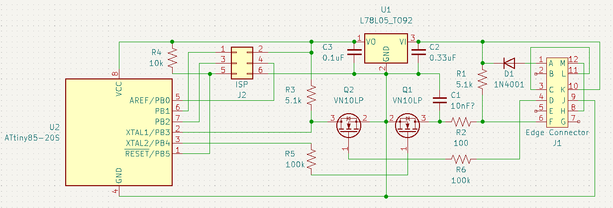
As far as my need for a viable signal goes, I have been looking into options for variable-frequency frequency-doubling circuits.. And short of some specialized low-freq PLL stuff, I think this might best be handled via a microcontroller calculating pulsewidth and triggering on each edge of the 2k ppm signal. Unfortunately that solution will take some time to get into a functional state, but I have started on a design to be plugged into C246 where the old cruise module connected originally. If any EE-inclined members want to look it over and give some tips, I would greatly appreciate it; My electrical skill is more about diag/repair, much less about electrical circuit design.
Regardless, thank you to everyone who has reached out or replied here! Really awesome to see our niche group being so friendly and helpful.
Next time, before submitting a schematic for review, please assign reference designators to all components. When many compoments are labelled with question marks, that makes it hard to talk about a specific part.
A hypothesis and logical consequence: If the 86+ speedo board works mainly at 5V, and the signal to the cruise module is just passed over a simple wire (no voltage level modification), then this implies that the cruise module works with a 5V square wave input.
If the inputs/outputs operate at 5V, then you could eliminate Q1, Q2 (and their associated 100kΩ / 5.1kΩ resistors), and the design considerations that they imply.
For the input, I think a 10kΩ resistor between the 2000 PPM signal and microcontroller pin would suffice. This would limit current into the protection diodes of the input pin, if that were to happen.
For the output, I think a 100Ω resistor (for some small short-circuit protection) between the microcontroller and C1 would suffice. What is the value of C1? Undecided? Perhaps 10 nF would not slow down the signal too much?
A diode in series with the 12V power input would protect the circuit against a reverse-polarity battery connection. This is standard practice in automotive.
You have output capacitor C3 at the regulator output, but it is also customary to decouple the power supply locally right at the microcontroller. Some capacitance installed as directly as possible between the VCC and GND pins of the microcontroller pins would be preferred. The datasheet of the microcontroller likely gives a suggested configuration of decoupling capacitance.
When the programmer is not connected to the ISP connector, the nRESET pin is left floating in the air. Stray voltage could cause the pin to go high or low, possibly randomly resetting the microcontroller. This pin should probably be tied to VCC through a resistor, but again, check the datasheet of the microcontroller for the suggested reset circuit configuration.
Thank you for the reply! I do apologize about the unlabeled components- I caught it just after I hit the post button.. As for the FET-switched signals for level shifting, according to the I/O schematic for the 1226864/1226156, the VSS input to the ECM from the speedo is pulled to 12v by a 5.1k resistor inside the ECM, and the speedo board triggers to ground through a transistor for signal formation. Along those lines, I am assuming a 0-12v square-wave.
I hadn't considered reverse voltage protection, but you are absolutely right in that it should be a standard consideration. As for the 5v supply, I was unable to find mention of it in the ATTiny datasheet with a quick ctrl+f search, and I have yet to do any PCB layout, but I am figuring that the regulator and output filter cap may be close enough onboard to prevent any issues. I had also considered using a resistor/zener dropper for a crude 5v supply, but figured that would be less stable than a linear regulator, require even more filtering, be less energy efficient, and likely end up costing more than the regulator + caps.
I will definitely use a pullup for the reset pin, as well as a current-limiting resistor for the signal output; Both things I had overlooked as well. The value of C1 hadn't been determined yet, but I figured I will likely want something there for switching noise reduction. The operating frequency range of the 4k ppm signal will be around 20-90 Hz, corresponding with a 20-80 mph range, and I hadn't been sure how that corresponds to capacitance value for filtering. Hoping I don't need to use an RC LPF to prevent harmonics.
I kinda really like the no-splice/no-cut mod idea, so I will probably be moving forward with designing and ordering some pcbs and such once I am confident in the schematic. If I get it to work, I'll release the code for the MCU, as well as the full KiCad project open-source on GitHub.
Originally posted by TGYK256: Thank you for the reply! I do apologize about the unlabeled components- I caught it just after I hit the post button.. As for the FET-switched signals for level shifting, according to the I/O schematic for the 1226864/1226156, the VSS input to the ECM from the speedo is pulled to 12v by a 5.1k resistor inside the ECM, and the speedo board triggers to ground through a transistor for signal formation. Along those lines, I am assuming a 0-12v square-wave.
I can confirm that the 2000 PPM output to the ECM is a switched ground (the transistor next to the 1 mF GLASS capacitor in your speedo schematic), pulled up by the ECM. I investigated this when I had to configure an aftermarket engine computer to accept input from the Fiero speedo.
We don't know what the cruise control module expects as input. I would suggest powering up the cruise module; if you measure a voltage at the 4000 PPM input, then you could conclude that their is a pullup resistor to the measured voltage. If you connect the input to ground through an ammeter, then you could figure what the cruise control has for a pullup resistor, if equipped with one.
quote
Originally posted by TGYK256: I had also considered using a resistor/zener dropper for a crude 5v supply, but figured that would be less stable than a linear regulator, require even more filtering, be less energy efficient, and likely end up costing more than the regulator + caps.
An off the shelf regulator would work. Using more discrete parts is just how they did things back then.
I would tend to the resistor/zener setup if I wanted to keep things period-correct on a classic car
quote
Originally posted by TGYK256: The operating frequency range of the 4k ppm signal will be around 20-90 Hz, corresponding with a 20-80 mph range, and I hadn't been sure how that corresponds to capacitance value for filtering. Hoping I don't need to use an RC LPF to prevent harmonics.
Note that most equations relating to filter attenuation are applicable to sine waves.
A square can be considered to be made up of a series of sine waves added together:
So, a 90 Hz square wave could be considered equivalent to a combination of a 90 Hz sine wave + 270 Hz sine wave + 450 Hz sine wave + 630 Hz sine wave, and so on...
If you have a filter that passes 90 Hz sine waves, but blocks 270+ Hz sine waves, then the square wave won't look like a square wave anymore once it goes through the filter; all that would remain is the 90 Hz sine!
Without going to deep into math/calculations, a good approach if you're making a PCB is to leave an empty footprint available for a capacitor, if needed. Then, you can make tests, and slowly increase the capacitor value, and see what it does to the signals (looking at the oscilloscope).
Originally posted by pmbrunelle: I can confirm that the 2000 PPM output to the ECM is a switched ground (the transistor next to the 1 mF GLASS capacitor in your speedo schematic), pulled up by the ECM. I investigated this when I had to configure an aftermarket engine computer to accept input from the Fiero speedo.
We don't know what the cruise control module expects as input. I would suggest powering up the cruise module; if you measure a voltage at the 4000 PPM input, then you could conclude that their is a pullup resistor to the measured voltage. If you connect the input to ground through an ammeter, then you could figure what the cruise control has for a pullup resistor, if equipped with one.
I took your advice and did probe my "V8" labeled digital cruise module at the VSS input, I surprisingly found a voltage at 5.7ish volts. While this is good to know (We don't need to pullup the VSS line to 12v like how it is done in the Fiero.. Furthermore, doing so might cause the magic smoke to do its' thing.) I don't think I will be sinking the current directly with the ATTiny85. The measured voltage is close enough to the listed max (VCC + 0.5V) input voltage that I would rather err on the side of caution and drive via a FET. I didn't measure the current just yet, but will do so before finalizing the design- I want to make sure I don't overcurrent the FET.
quote
Originally posted by pmbrunelle:
An off the shelf regulator would work. Using more discrete parts is just how they did things back then.
I would tend to the resistor/zener setup if I wanted to keep things period-correct on a classic car
I definitely agree, especially for the cost of ~1-2 bucks per regulator on digikey for small quantities.
quote
Originally posted by pmbrunelle:
Note that most equations relating to filter attenuation are applicable to sine waves.
A square can be considered to be made up of a series of sine waves added together:
So, a 90 Hz square wave could be considered equivalent to a combination of a 90 Hz sine wave + 270 Hz sine wave + 450 Hz sine wave + 630 Hz sine wave, and so on...
If you have a filter that passes 90 Hz sine waves, but blocks 270+ Hz sine waves, then the square wave won't look like a square wave anymore once it goes through the filter; all that would remain is the 90 Hz sine!
Without going to deep into math/calculations, a good approach if you're making a PCB is to leave an empty footprint available for a capacitor, if needed. Then, you can make tests, and slowly increase the capacitor value, and see what it does to the signals (looking at the oscilloscope).
I had heard of Fourier stuff before, but I guess I failed to connect it to the concept of filtering. My inexperience is really showing! I think that I will definitely leave the output filter cap in the schematic with a TBD value, as well as a blank spot on the PCB for testing. I feel like the frequency of the signal is low enough that I shouldn't have to worry too much about reflections and harmonics, but this is based entirely on a gut feeling. My main concern is for switching-noise spiking voltage on the rising and falling edges of the signal.
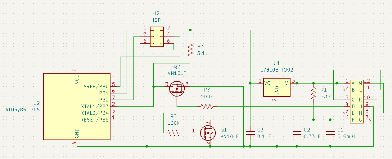
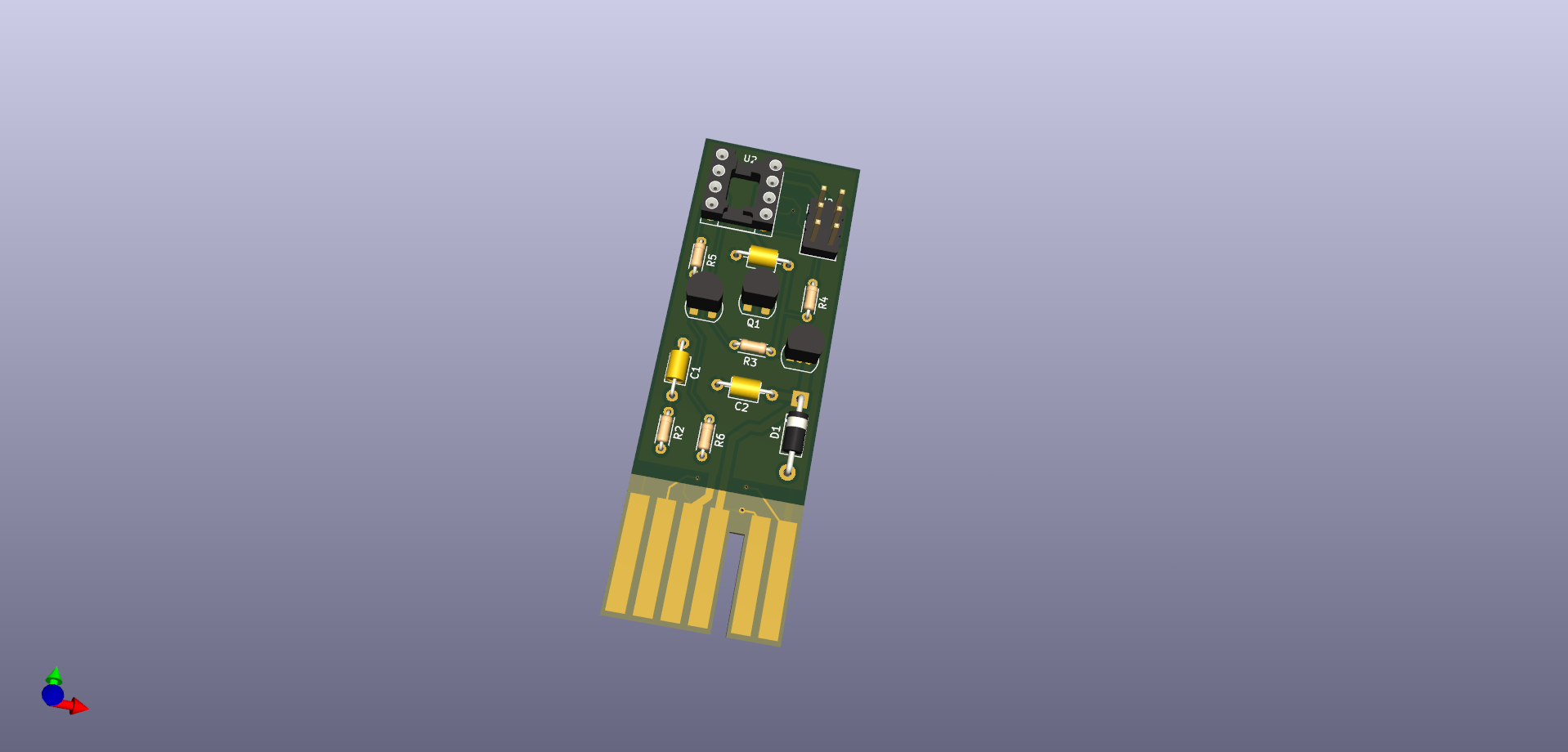
As an update, I removed the 12v pullup from the schematic and spent several hours fumbling my way through putting together a PCB. Note that in the image, I forgot to disable the model for the C1 cap before snapping a pic.
R5 and R6 seem to have very high values. The MOSFET gates are capacitive; together with the 100 kΩ resistors, this will slow down the turn-on/off times.
What is the function of these resistors? Is it so that the driving circuitry doesn't see the MOSFET gate load when switching? They kind of seem high, I think I would go for 10 kΩ. At 10 kΩ that shouldn't bother anything connected.
Another common practice in automotive is to protect PCB connector pins against electrostatic discharge. For instance, you walk across the floor, pick up some charge, then touch the edge tabs, and you zap your circuit.
The gate of Q2 is fragile and is exposed to the outside world. It gets zapped at 20V. An "SA10A" TVS from its gate to ground could protect it. In automotive (today at least, maybe less so in Fiero times), a TVS diode is commonly used to protect PCB connectors from the outside world.
The drain of Q1 is less fragile, as it can handle 60V. I think the connector pin "F" could be protected with a "SA30A" diode. This one can conduct at a much higher voltage and really have no effect in normal operation.
A static discharge at the power input can be partially absorbed by C2, so a TVS is less important here, but you could also use the SA30A here at pin "K".
Static protection is not mandatory for the hobbyist, but if this is omitted, then you need to be more careful about grounding yourself before touching the connector pins (something that doesn't necessarily happen in an automotive factory) or the associated harness.
quote
Originally posted by TGYK256: I kinda really like the no-splice/no-cut mod idea
How does this work? It plugs into the unused contacts of the speedo connector?
quote
Originally posted by TGYK256: If I get it to work, I'll release the code for the MCU, as well as the full KiCad project open-source on GitHub.
Cool, link to the repo here when you're done. PFF is the biggest gateway to Fiero information, so if anyone needs to find that information, they would most likely find it through here.
Originally posted by pmbrunelle: R5 and R6 seem to have very high values. The MOSFET gates are capacitive; together with the 100 kΩ resistors, this will slow down the turn-on/off times.
What is the function of these resistors? Is it so that the driving circuitry doesn't see the MOSFET gate load when switching? They kind of seem high, I think I would go for 10 kΩ. At 10 kΩ that shouldn't bother anything connected.
You guessed correctly in my intention, I don't want to drag down the input square wave and prevent the ECM from receiving the same signal. I chose 100k on a whim, intending to do some actual maths and pick a suitable value a bit later on (Likely after hours of research, trying to figure out how to properly size a high-Z input resistor.)
quote
Originally posted by pmbrunelle: Another common practice in automotive is to protect PCB connector pins against electrostatic discharge. For instance, you walk across the floor, pick up some charge, then touch the edge tabs, and you zap your circuit.
The gate of Q2 is fragile and is exposed to the outside world. It gets zapped at 20V. An "SA10A" TVS from its gate to ground could protect it. In automotive (today at least, maybe less so in Fiero times), a TVS diode is commonly used to protect PCB connectors from the outside world.
The drain of Q1 is less fragile, as it can handle 60V. I think the connector pin "F" could be protected with a "SA30A" diode. This one can conduct at a much higher voltage and really have no effect in normal operation.
A static discharge at the power input can be partially absorbed by C2, so a TVS is less important here, but you could also use the SA30A here at pin "K".
Static protection is not mandatory for the hobbyist, but if this is omitted, then you need to be more careful about grounding yourself before touching the connector pins (something that doesn't necessarily happen in an automotive factory) or the associated harness.
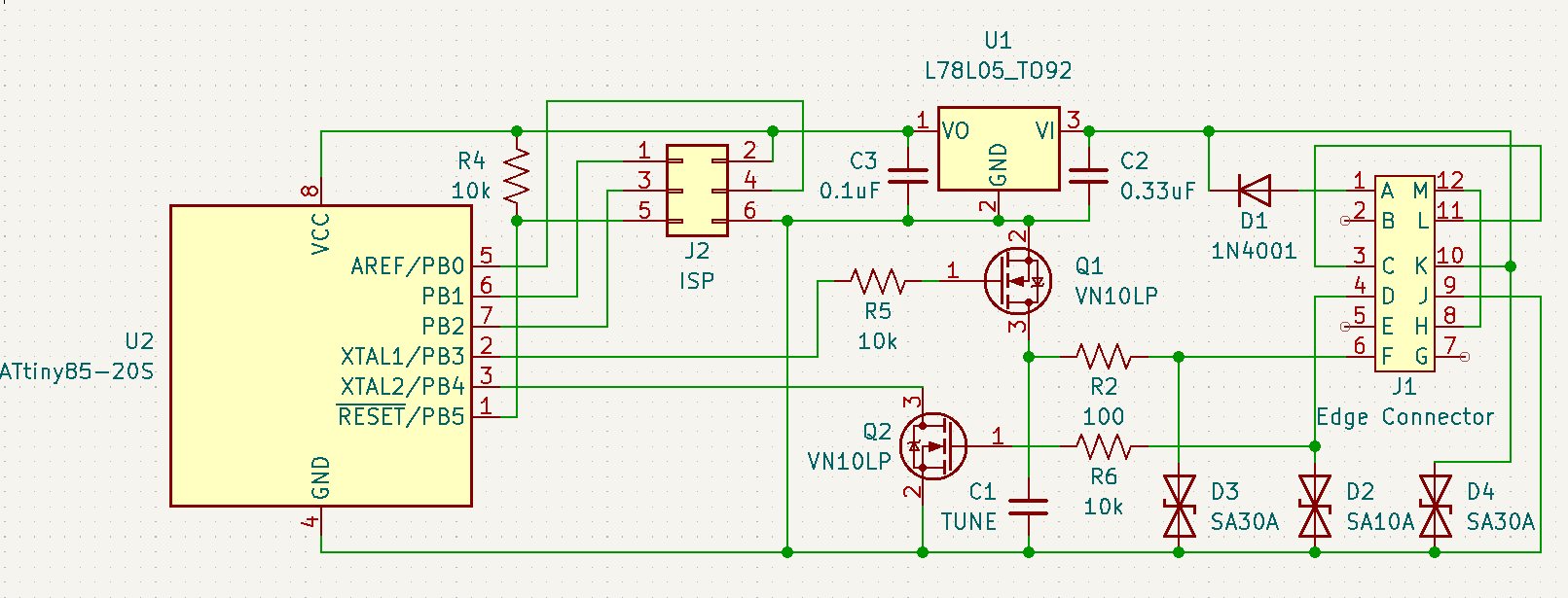
I wasn't going to put in any sort of ESD or even reverse voltage protection at first, as I was intending to just do this once, for myself, probably on protoboard. Since I'm going through the trouble of designing a PCB, I might as well include some level of standard protections. Like most of my electrical knowledge, I had heard of TVS diodes before, but had filed them in the back of my mind poorly. (I completely forgot they existed) So thank you again for the very helpful advice! I added two of them on the input and output signal lines, as well as one on the 12V input rail. I also removed the external 5v pullup in favor of the one built-in on the ATTiny85.
Updated schematic:
quote
Originally posted by pmbrunelle: How does this work? It plugs into the unused contacts of the speedo connector?
It's actually meant to plug into the harness in-place of the old vacuum-servo controller. Spent more time than I care to admit making that card-edge connector footprint.
quote
Originally posted by pmbrunelle: Cool, link to the repo here when you're done. PFF is the biggest gateway to Fiero information, so if anyone needs to find that information, they would most likely find it through here.
100% intend to! I want to make sure I have a viable and working solution first. Would hate for someone to spend the money on a PCB and components on a half-baked project they found here that won't work for em!
Originally posted by pmbrunelle: The gate of Q2 is fragile and is exposed to the outside world. It gets zapped at 20V. An "SA10A" TVS from its gate to ground could protect it.
quote
Originally posted by TGYK256: I had heard of TVS diodes before, but had filed them in the back of my mind poorly. (I completely forgot they existed) So thank you again for the very helpful advice! I added two of them on the input and output signal lines, as well as one on the 12V input rail.
TVS diodes are typically located at the connector pins, but exceptionally for the SA10A of Q2, the TVS needs to be located between the resistor R6 and the MOSFET Q2.
This TVS needs to have a low clamping voltage to protect the MOSFET gate, but if you put it directly at the connector, it may conduct with 12V seen in normal operation. So, the TVS in this case should be "hidden" behind the resistor, so that it doesn't influence the stock ECM too much.
quote
Originally posted by TGYK256: I also removed the external 5v pullup in favor of the one built-in on the ATTiny85.
The internal pullup resistor of a microcontroller typically has a higher resistance than something you could put externally, so there could be less noise immunity especially with longer wires. That said, the internal pullup should work for your use case, with Q2 located nearby on the same PCB.
Originally posted by pmbrunelle: TVS diodes are typically located at the connector pins, but exceptionally for the SA10A of Q2, the TVS needs to be located between the resistor R6 and the MOSFET Q2.
This TVS needs to have a low clamping voltage to protect the MOSFET gate, but if you put it directly at the connector, it may conduct with 12V seen in normal operation. So, the TVS in this case should be "hidden" behind the resistor, so that it doesn't influence the stock ECM too much.
I might be wrong here, but instead of moving the TVS connection point behind the resistor, I've been looking into more fitting N-channel TO-92-3 FETs. My reasoning behind this is that the resistor will limit the shunting current ability of the TVS in an overvoltage situation, according to ohm's law. Also, I believe the TVS would be continually cycling during normal operation.. At a minuscule current behind the resistor, but still passing current nonetheless with a 10V reverse standoff voltage.
I believe that the 2N7000 would be fitting, bringing the VGS max up to 30V, and allowing the use of an SA16A TVS (max clamping of 26V) instead of an SA10A, which would bring the reverse standoff up to 16V, keeping it from operating during nominal vehicle running conditions. Thoughts?
quote
Originally posted by pmbrunelle:
The internal pullup resistor of a microcontroller typically has a higher resistance than something you could put externally, so there could be less noise immunity especially with longer wires. That said, the internal pullup should work for your use case, with Q2 located nearby on the same PCB.
For a bit of context, the current trace length for the input FET is < 10mm. I'm unsure if that would be long enough to be influenced by noise, and it has a full groundplane coverage from the other side of the board. I know that the automotive environment is pretty noisy, but I don't have really any knowledge to base onboard noise reduction off of.
[This message has been edited by TGYK256 (edited 08-29-2025).]
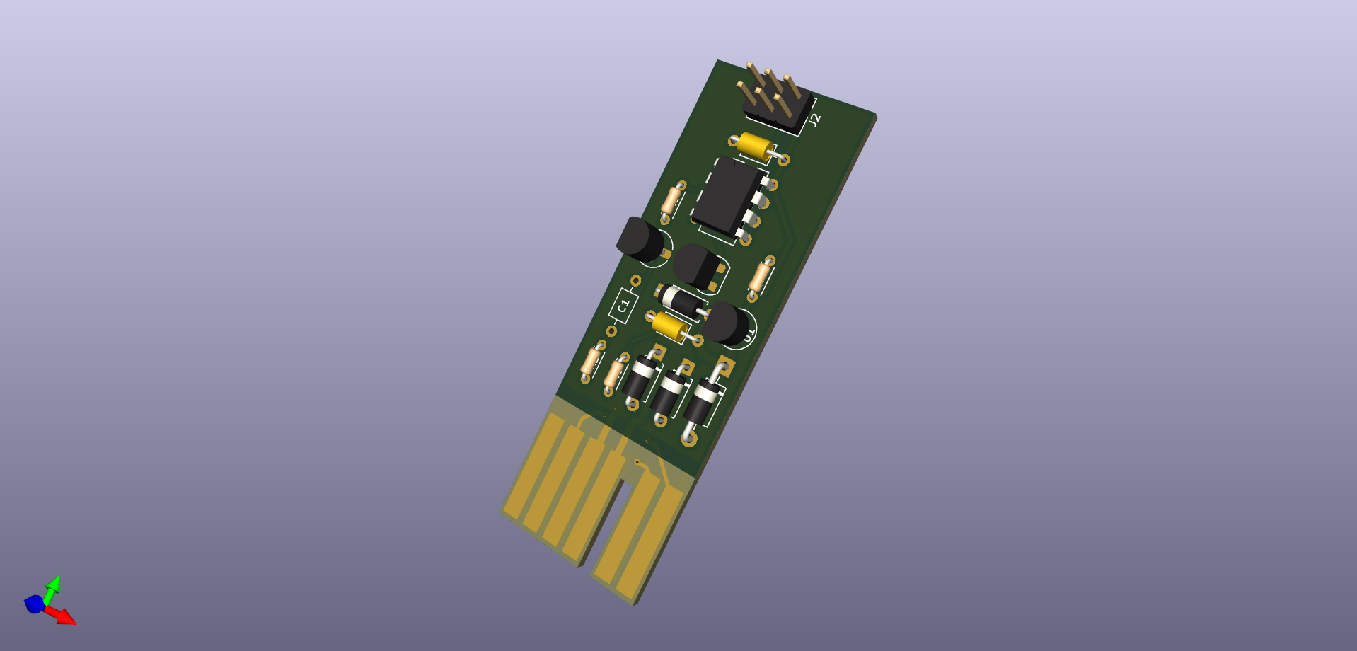
Update: I had to change the schematic slightly to make use of the Timer/counter 0 output, as well as the INT0 input. I believe I have what should be a functional product at this point, but have done no debugging yet. Going to be "Proofreading" and double-checking everything before ordering a small batch of boards and at least 1x BOM for testing. Although I can't guarantee that this works at all, I have pushed my KiCAD project as well as my Platformio-based code to github. The repo can be found here.
Thank you again to everyone who has reached out to help in one way or another! I am unsure if I should keep bumping this thread with new updates or start a new one - Any mods that can weigh in on this?
Your idea of the 2N7000 and high TVS voltage is good.
It is good that you verified what microcontroller peripherals/timers are available on which pins. Some folks at my work don’t check this adequately before making a PCB!
PFF doesn’t have much in the way of moderation, so you could make a new about your project, but leave links to both threads so the information can be found regardless of the entry point.