Since I am adding 4 Cylinder support to the Fiero ALDL Monitor and Adapter, I am adding slides for the IL4 (I already have the V6 done).
Can anyone help me "place" the red identifiers on the drawing? I had a V6 in front of me but I don't have access to an IL4. I could dig through manauls but not everything is in one spot.
Updated from RWDPLZ's response:
Any help is appreciated (just a few more to go). Just chime in with comments in like: Item 3 is at grid C1 (which is already done).
Thanks, Paul
------------------ Paul Romsky
[This message has been edited by Romsk (edited 06-08-2025).]
They vary by year, but on an 84 the fuel filter would be at about H6, air intake filter at O7 (the whole round area), and oil filter around where you have F3
O2 sensor B around M2 Fuel pressure regulator N2 at N7 (part of the TBI assembly) Oil pressure sending unit (or switch on 84) at P7 on engine block under intake Fan switch N12 at J2 Coolant temp sensor D at I6 Temperature gauge sending unit E at I4 Ignition coil I at J8
Only thing to add, since you're including the PCV valve... the Fiero also has a mechanical temperature valve located inside the air cleaner, which controls the ThermAC (used for bringing in either cold or warm air to the intake).
Yes, I now remember you mentioning that too me in our emails. I will add it. Can you approximate its Grid location. Even if it is on top of something else. There is a lot in the Air Cleaner and TB below it. I will make it fit.
It looks like I will need a separate drawing for the 1987-1988 L4 Engine as it has the DIS.
Also, can you confirm: There is no Cold Start Switch or Injector in the L4's.
Thanks, Paul
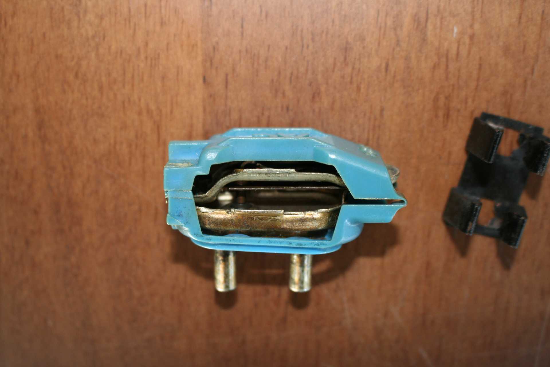
There is for sure, no cold start injector for 84-86 Fieros. It uses the ThermAC to manage cold / hot air to regulate where a cold start injector would instead provide more fuel when cold. It uses this sensor (removed):
I did have a 1988 engine, and I saw nothing of the sort on that engine either (though it has a different throttle body than the 84-86 engine). The 1987-1988 DOES have an air intake temperature sensor, which the 84-86 Fieros do not have.
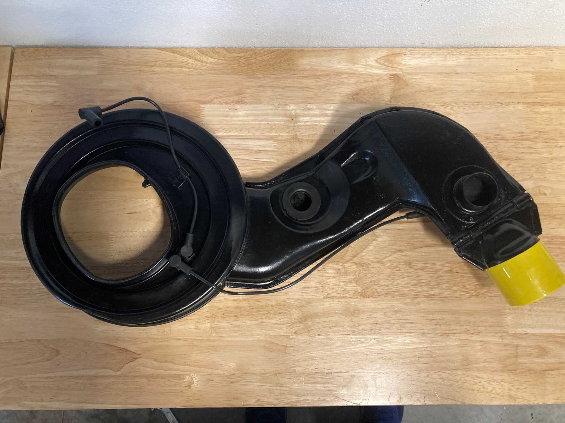
Let me see if I can find a picture of it (the mechanical valve) installed on the air cleaner. It's installed on the INSIDE oft he air cleaner... with the vacuum lines connecting beneath it (where you see the elbow vacuum lines conneting side by side):
It's mounted inside the air cleaner and inside the air filter, intentionally, so that it's getting the regulated air THAT the ThermAC temperature sensor regulates... so it mechanically knows exactly how much or how little vacuum to allow.
I'll look for the obvious picture that negates the need for these other pictures... haha... give me a few minutes. I might just take the lid off and take a picture of my engine.
Thanks, that photo of the underside of the Air Cleaner is enough to on as to where the ThermAC valve is located.
I will remove Cold Start Switch and Injector from the L4 diagrams in my GUI. I have two now. One for Distributor engines and the other for DIS engines.
So 1987-1988 L4 engines have a IAT (or MAT) sensor. I will show that on my drawings for those years only.
I appreciate photos but, for the IAT/MAT location, a Grid position (see drawing at the start of this thread) is all I need. It doesn't have to be exact, just close enough for people to find.
Thanks.
Yes, for 87-88 engines, there is a Manifold Air Temperature sensor that is located on the intake manifold in the rear passenger corner of it.
This thread has some good pictures... further down, Patrick explains that it's a MAT sensor, which he got from Ogre's Cave...
Since it is on the Manifold and not the Air Cleaner, I will show it as a MAT sensor where you said it is located. That appears to be Grid position R7 (or in that general area)
One final item: Is there a Tach Filter on L4's? If so, where is it located?
These slides will be in the next release of the GUI. Remember, you can download the GUI and see these slides in the Set-Up panel.
The Edge Connectors just shipped from Hong Kong, I should have them in 2 weeks.
Paul
Sorry! I haven't responded to my e-mails. I had to fly out, but checked when I got back. I do have a harness with connectors, but it was for an 87 SE 5-Speed... so it has the plugs and not the edge connectors (like on 8088 computers for the RLL/MFM drives, haha...).
And for the Tach Filters:
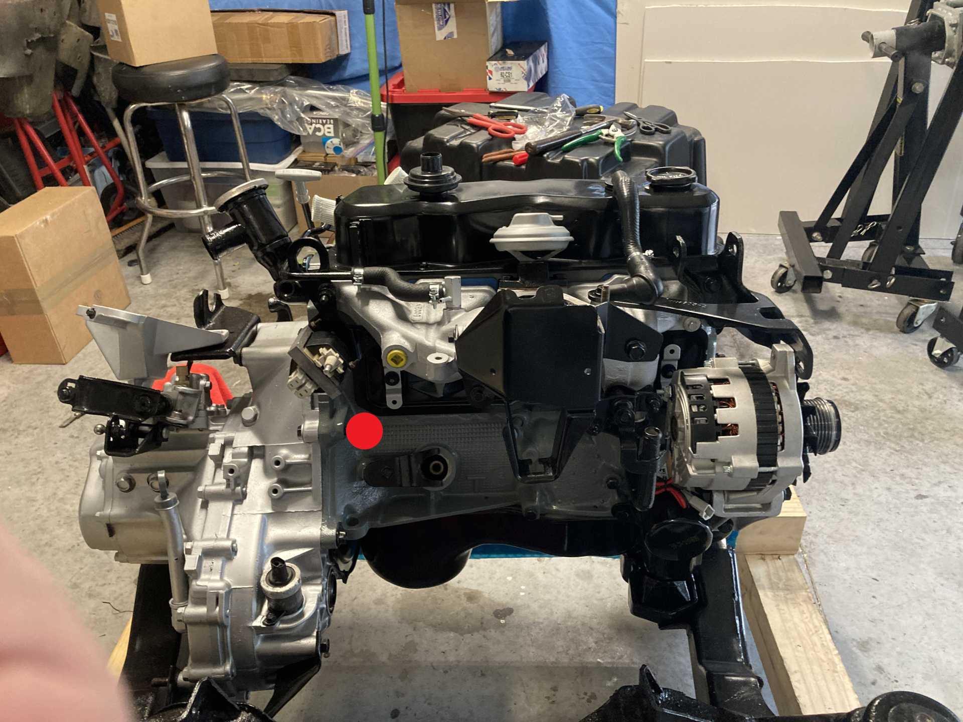
84-86 : Tach Filter is located below the ignition coil, and mounts to the side of the transmission. Basically, the coil mounts to the intake manifold (next to and beneath it), and the tach filter mounts directly below that to a bolt that sticks out from the transmission.
87-88 : No Tach Filter
Sorry, big picture, but this is an image of my daughter's engine before she re-installed it. The tach filter is not installed, but I put a red DOT where it's normally mounted.