Pennock's Fiero Forum
  Technical Discussion & Questions
  Simple individually controllable headlights

Post New Topic  Post A Reply
Email This Page to Someone! | Printable Version


next newest topic | next oldest topic
Simple individually controllable headlights by 1985 Fiero GT
Started on: 03-13-2024 04:50 PM
Replies: 8 (174 views)
Last post by: 1985 Fiero GT on 03-14-2024 11:00 PM
1985 Fiero GT
Member
Posts: 406
From: New Brunswick, Canada
Registered: May 2023


Feedback score: N/A
Leave feedback

Rate this member

Report this Post03-13-2024 04:50 PM Click Here to See the Profile for 1985 Fiero GTSend a Private Message to 1985 Fiero GTEdit/Delete MessageReply w/QuoteDirect Link to This Post
I made a simple system for individually controlling the headlight motors on the gen 1 system to enable "winking". This only requires 2 wires to be fed through the front firewall, and it keeps the factory switch working as it is supposed to, without mangling the factory wiring (cutting 2 wires, and tapping into a few others), the system also remains entirely unpowered when the headlights are off, so it won't drain the battery.

To do this I am using one additional relay for each headlight, mounted right with the factory headlight relay. The relay is engaged by a power wire running into the cabin (to a 3 way switch powered by the yellow headlight wire on the headlight switch), and is grounded in the headlight bucket. The switched input is the pink wire running to each factory headlight relay (which is cut), with the normally closed output being the pink wire to the factory relays (when new relays are unpowered, headlight up signal flows through the new relay to the factory relay), and the normally open output taps into the blue wire going directly into the headlight motor (when headlights are up, isolation relay isolates each headlights blue wire, and by having new relays spliced in before the factory relays, when new relays are engaged, power is diverted from the factory relays (which turn off) to the individual headlight down (blue) wire). Only difference in operation from factory is that the down power is coming from the headlight circuit (fusible link/breaker) instead of the parking lights fuse, when they are controlled by the new switch. When the new switch is turned off, the relays are not powered, and the headlight up and down is controlled by the headlight switch exactly like normal.

The switch I used is a 3 position rocker switch, so I can select left headlight down/right up, both up, right down/left up, you can use 2 seperate switches to truely individually control them, and even put both down. I made something that replaced the drivers side ashtray to mount that switch and another one in, that way it is hidden but easily accessible.

Attached is my attempt at a wiring diagram (if you can read my messy scribbling haha) and a link to it in action. Hopefully I explained it well enough, feel free to ask questions and point out problems!

https://youtu.be/1i-fImrrrLA

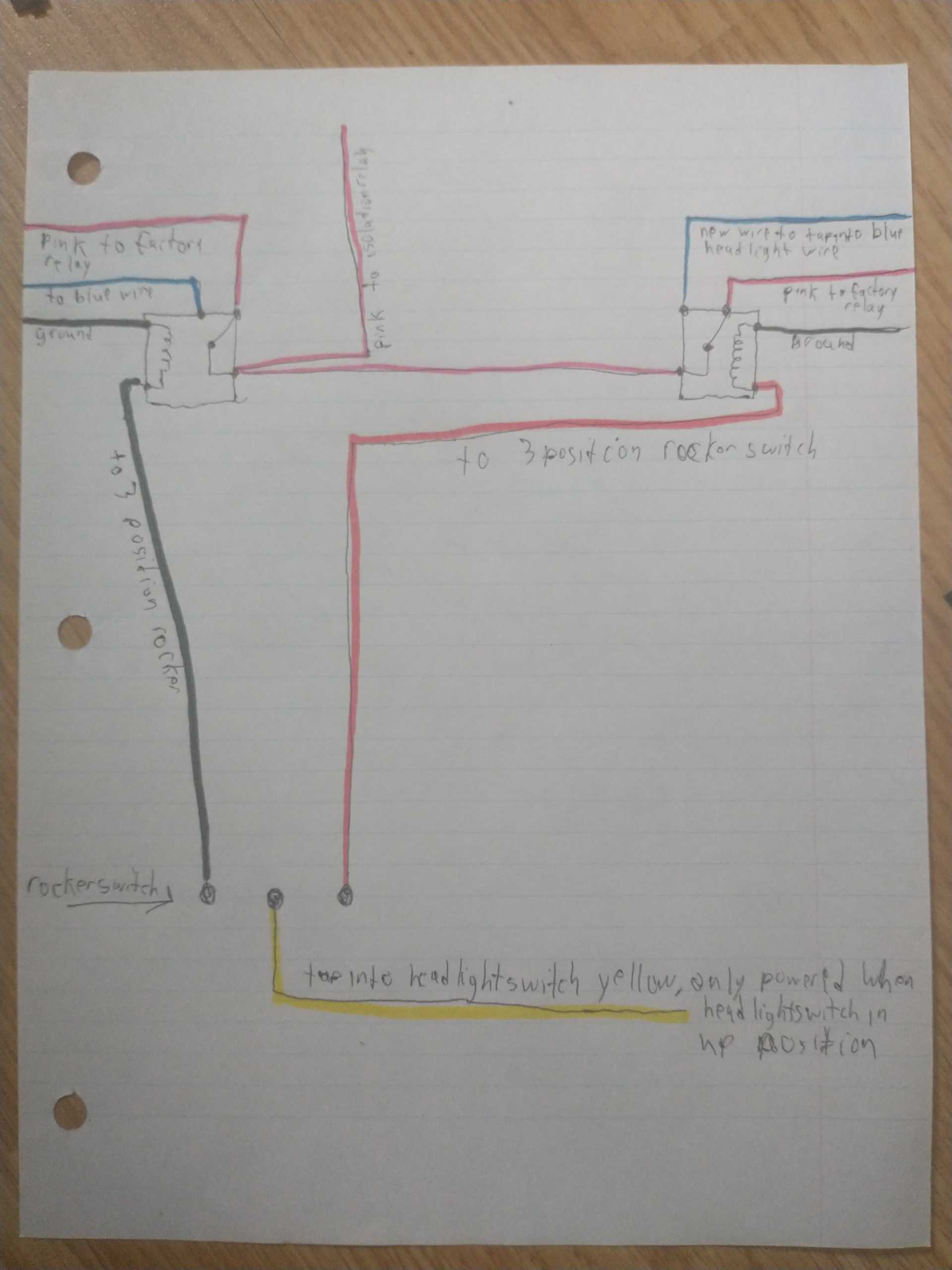
[This message has been edited by 1985 Fiero GT (edited 03-13-2024).]

IP: Logged
PFF
System Bot
theogre
Member
Posts: 32282
From: USA
Registered: Mar 99


Feedback score: N/A
Leave feedback


Total ratings: 568
Rate this member

Report this Post03-14-2024 10:12 AM Click Here to See the Profile for theogreClick Here to visit theogre's HomePageSend a Private Message to theogreEdit/Delete MessageReply w/QuoteDirect Link to This Post
Just Don't do that while driving.
Oh many will notice but not in a good way when cops see Defective/Dead HL then stop you.

What exactly relays did you use?
Amp Ratings printed on most relays & switches are only for AC Volts. Some may list Lower DC Volts but both are Resistive loads like tungsten lights. Inductive load like motors most only allow 1/4 to 1/3 of printed rating & even then can burn up fast w/o added protection & worse for DC motors. IOW say relay printed rating is 28dcv 10a but inductive rating is 1/4 to 1/3 of that & HL Motors pull 4-5 amps running & high when stalled for any reason.

Also Using the motors often just means motor problems sooner. Both Gen1 & Gen2 systems "hate" being open close fast more so repeatedly like kids playing with them.
Examples:
Gen1 HL motors & many others hate switching direction fast. Let the motor stop @ end of travel before releasing the "blink" switch. Otherwise the "blink system" will act as electric & mechanical Hammers causing huge stress to the motor & gears.

Gen2 Module was made to handle normal operation but repeat open/close can overheat the MOSFETS because have very small heatsinks w/ just extra copper on the board.
(You can't "blink" Gen2 using the above method)

------------------
Dr. Ian Malcolm: Yeah, but your scientists were so preoccupied with whether or not they could, they didn't stop to think if they should.
(Jurassic Park)


The Ogre's Fiero Cave

IP: Logged
1985 Fiero GT
Member
Posts: 406
From: New Brunswick, Canada
Registered: May 2023


Feedback score: N/A
Leave feedback

Rate this member

Report this Post03-14-2024 10:44 AM Click Here to See the Profile for 1985 Fiero GTSend a Private Message to 1985 Fiero GTEdit/Delete MessageReply w/QuoteDirect Link to This Post
 
quote
Originally posted by theogre:

Just Don't do that while driving.
Oh many will notice but not in a good way when cops see Defective/Dead HL then stop you.

What exactly relays did you use?
Amp Ratings printed on most relays & switches are only for AC Volts. Some may list Lower DC Volts but both are Resistive loads like tungsten lights. Inductive load like motors most only allow 1/4 to 1/3 of printed rating & even then can burn up fast w/o added protection & worse for DC motors. IOW say relay printed rating is 28dcv 10a but inductive rating is 1/4 to 1/3 of that & HL Motors pull 4-5 amps running & high when stalled for any reason.

Also Using the motors often just means motor problems sooner. Both Gen1 & Gen2 systems "hate" being open close fast more so repeatedly like kids playing with them.
Examples:
Gen1 HL motors & many others hate switching direction fast. Let the motor stop @ end of travel before releasing the "blink" switch. Otherwise the "blink system" will act as electric & mechanical Hammers causing huge stress to the motor & gears.

Gen2 Module was made to handle normal operation but repeat open/close can overheat the MOSFETS because have very small heatsinks w/ just extra copper on the board.
(You can't "blink" Gen2 using the above method)


Yes, I don't intend to do it much if at all, just saw something that hadn't been done much before and thought I could do it. And because the headlight bulbs stay on, when "winking" theoretically the most they could cite me for is misaligned headlights, not to mention the is basically no law enforcement where I live, and no people on the roads, the only time I could "wink" to show off to people is at an event or when meeting friends.

I used these relays here:
https://www.digikey.ca/en/p...C1-12C-N-X/12352857?
40 amps DC in the normally open (down), 30 amps DC in the normally closed (up) position, and they only directly power the motors going down, which draws less power, they power the factory relays which then power the motors going up. So 40 amps resistive going down should hopefully be good, and maybe 1 amp going up, powering the factory relay.

I definitely don't intend to use this much, maybe a dozen or so times at car shows, with friends, etc. this is probably the most gaudy thing I've done to my Fiero!
IP: Logged
theogre
Member
Posts: 32282
From: USA
Registered: Mar 99


Feedback score: N/A
Leave feedback


Total ratings: 568
Rate this member

Report this Post03-14-2024 11:27 AM Click Here to See the Profile for theogreClick Here to visit theogre's HomePageSend a Private Message to theogreEdit/Delete MessageReply w/QuoteDirect Link to This Post
I now read the datasheet... https://pickercomponents.com/pdf/Relays/PC792A.pdf
Notes:
A part# w/ "missing field" then = field is blank/Nil for ordering info chart.
Unlike most Fiero Relays, this Coil has no diode or resistor as "surge protection." (as PN is missing D, D1 or R.)

Yes since controls just the relays should be good.

Datasheet Ratings are only Resistive loads. I expect 8-10A Max for small inductive but maker only said:
 
quote
Values can change due to the switching frequency, desired reliability levels, environmental conditions, and in-rush current levels. It is recommended to test to actual load conditions for the applicaiton. It is the users responsibility to determine the performance suitability for their specific application. The use of any coil voltage less than the rated coil voltage may compromise the operation of the relay.

[This message has been edited by theogre (edited 03-14-2024).]

IP: Logged
1985 Fiero GT
Member
Posts: 406
From: New Brunswick, Canada
Registered: May 2023


Feedback score: N/A
Leave feedback

Rate this member

Report this Post03-14-2024 12:10 PM Click Here to See the Profile for 1985 Fiero GTSend a Private Message to 1985 Fiero GTEdit/Delete MessageReply w/QuoteDirect Link to This Post
 
quote
Originally posted by theogre:

I now read the datasheet... https://pickercomponents.com/pdf/Relays/PC792A.pdf
Notes:
A part# w/ "missing field" then = field is blank/Nil for ordering info chart.
Unlike most Fiero Relays, this Coil has no diode or resistor as "surge protection." (as PN is missing D, D1 or R.)

Yes since controls just the relays should be good.

Datasheet Ratings are only Resistive loads. I expect 8-10A Max for small inductive but maker only said:


Ok, should be good, as even with the factory wiring, the blue +down wire is basically sent straight to the headlight switch, with no diodes that I can see in the diagram, the up headlight relay does seem to have diodes, and up is still controlled through the factory relay, so should be good.
IP: Logged
theogre
Member
Posts: 32282
From: USA
Registered: Mar 99


Feedback score: N/A
Leave feedback


Total ratings: 568
Rate this member

Report this Post03-14-2024 06:26 PM Click Here to See the Profile for theogreClick Here to visit theogre's HomePageSend a Private Message to theogreEdit/Delete MessageReply w/QuoteDirect Link to This Post
Most OE Relays don't show diodes In them. Not even in Car maker's FSM & leave the diode out of most sections/diagrams. May not show even in the Datasheets if you can get them. Only by chance some GM data was release to public after Spinoff all parts to Delphi then later went bankrupt & sold. I & others know by tearing apart dead relays.

Only some relays/coils like AC clutch coil shows a Diode as part of the plug to that in the FSM etc.

The "flyback" diode reduces noise/surge when the power is turn Off. In big Coils like AC Clutch, the surge can be --700 or more volts that blow thru the wires & controls cooking ECM & more when the diode fails. Yes, Minus 700 Volts. Smaller coils used in relays can easy push out --100 to --300 volts when turn Off.
IP: Logged
1985 Fiero GT
Member
Posts: 406
From: New Brunswick, Canada
Registered: May 2023


Feedback score: N/A
Leave feedback

Rate this member

Report this Post03-14-2024 07:03 PM Click Here to See the Profile for 1985 Fiero GTSend a Private Message to 1985 Fiero GTEdit/Delete MessageReply w/QuoteDirect Link to This Post
 
quote
Originally posted by theogre:

Most OE Relays don't show diodes In them. Not even in Car maker's FSM & leave the diode out of most sections/diagrams. May not show even in the Datasheets if you can get them. Only by chance some GM data was release to public after Spinoff all parts to Delphi then later went bankrupt & sold. I & others know by tearing apart dead relays.

Only some relays/coils like AC clutch coil shows a Diode as part of the plug to that in the FSM etc.

The "flyback" diode reduces noise/surge when the power is turn Off. In big Coils like AC Clutch, the surge can be --700 or more volts that blow thru the wires & controls cooking ECM & more when the diode fails. Yes, Minus 700 Volts. Smaller coils used in relays can easy push out --100 to --300 volts when turn Off.


Ok, makes sense, so the relay itself generates an electrical surge through its signal wires when turned off? What happens when the signal wire is physically disconnected from everything, like mine with a physical switch, where does that surge go?
IP: Logged
theogre
Member
Posts: 32282
From: USA
Registered: Mar 99


Feedback score: N/A
Leave feedback


Total ratings: 568
Rate this member

Report this Post03-14-2024 09:10 PM Click Here to See the Profile for theogreClick Here to visit theogre's HomePageSend a Private Message to theogreEdit/Delete MessageReply w/QuoteDirect Link to This Post
The coils Generate power as Magnet Field collapses when main power is turn Off.

That pulse can jump many types switch/relay contacts controlling them partly because contact don't open all the way fast enough to block it. More so on larger coils like AC clutch that have a Relay between ECM/BCM. In that case the pulse may jump to other things directly like control relay coil then flash fries the ECM & more.

[This message has been edited by theogre (edited 03-14-2024).]

IP: Logged
1985 Fiero GT
Member
Posts: 406
From: New Brunswick, Canada
Registered: May 2023


Feedback score: N/A
Leave feedback

Rate this member

Report this Post03-14-2024 11:00 PM Click Here to See the Profile for 1985 Fiero GTSend a Private Message to 1985 Fiero GTEdit/Delete MessageReply w/QuoteDirect Link to This Post
 
quote
Originally posted by theogre:

The coils Generate power as Magnet Field collapses when main power is turn Off.

That pulse can jump many types switch/relay contacts controlling them partly because contact don't open all the way fast enough to block it. More so on larger coils like AC clutch that have a Relay between ECM/BCM. In that case the pulse may jump to other things directly like control relay coil then flash fries the ECM & more.


Interesting, should be well enough isolated from critical components to not cause any harm though.
IP: Logged

next newest topic | next oldest topic

All times are ET (US)

Post New Topic  Post A Reply
Hop to:

Contact Us | Back To Main Page

Advertizing on PFF | Fiero Parts Vendors
PFF Merchandise | Fiero Gallery | Ogre's Cave
Real-Time Chat | Fiero Related Auctions on eBay


Copyright (c) 1999, C. Pennock