Pennock's Fiero Forum
  Technical Discussion & Questions
  Part numbers for temperature sensors

Post New Topic  Post A Reply
Email This Page to Someone! | Printable Version


next newest topic | next oldest topic
Part numbers for temperature sensors by Indy-453
Started on: 07-20-2021 01:46 AM
Replies: 4 (348 views)
Last post by: fierofool on 07-21-2021 09:28 AM
Indy-453
Member
Posts: 31
From: Calgary, AB, Canada
Registered: Nov 2019


Feedback score: N/A
Leave feedback

Rate this member

Report this Post07-20-2021 01:46 AM Click Here to See the Profile for Indy-453Send a Private Message to Indy-453Edit/Delete MessageReply w/QuoteDirect Link to This Post
Hello all,

I have an 84 Indy with air conditioning and a disaster of a wiring harness.

I think I have managed to track everything down for the temperature sensors, but I was hoping the experts could confirm my findings.

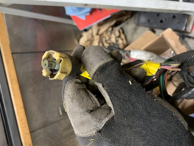
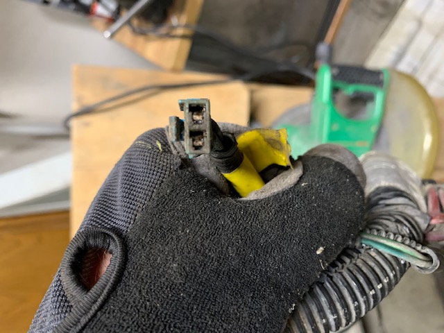
This is the two speed fan switch connector? Light Green with white stripe and dark green wires. I think the part number is AcDelco PT 313. This one is partly broken at the back and might get replaced. I did manage to find a NOS 2 speed sensor on ebay after the original one went missing when it was left in the head and the head when to the machine shop.


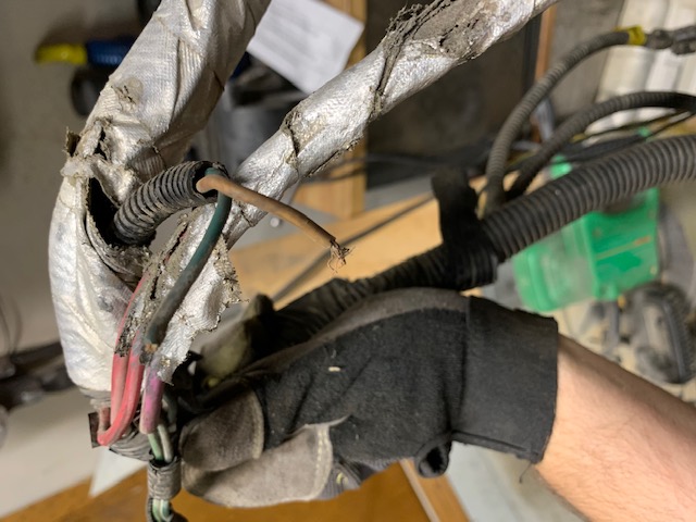
This broken green and tan or maybe orange wire is for the temperature gauges? Would the proper connector be an AcDelco PT 110?


I think this is the old style ECM temperature sensor connector? It was plugged into a sensor in the water neck. The sensor seems dead since its open circuit when I measure the resistance between the pin and the body. Or maybe its a one speed fan switch that was mistakenly purchased and that's why the car hasn't moved since 1996? It seems the replacement sensor is a GM 10045847 and the replacement connector would be a AcDelco PT 2386.

IP: Logged
PFF
System Bot
Tony Santucci
Member
Posts: 56
From: NC
Registered: Feb 2021


Feedback score: N/A
Leave feedback

Rate this member

Report this Post07-20-2021 07:04 AM Click Here to See the Profile for Tony SantucciSend a Private Message to Tony SantucciEdit/Delete MessageReply w/QuoteDirect Link to This Post
The first pic is the connector for the gauge/light sensor. https://www.amazon.com/gp/p...06_s00?ie=UTF8&psc=1

The second connector pic is the ECM temp sensor. You can get a sensor with a new pigtail to retrofit. https://shop.advanceautopar...temperature%20sensor
IP: Logged
fierofool
Member
Posts: 12955
From: Auburn, Georgia USA
Registered: Jan 2002


Feedback score:    (13)
Leave feedback


Total ratings: 154
Rate this member

Report this Post07-20-2021 08:24 AM Click Here to See the Profile for fierofoolClick Here to visit fierofool's HomePageSend a Private Message to fierofoolEdit/Delete MessageReply w/QuoteDirect Link to This Post
The Amazon sensor Tony linked is the correct one for the light green/white and dark green wires. Auto parts stores often sell the new "upgraded" sensor with a harness that has to be spliced in to replace this "old" sensor. Do not fall for this incorrect info. The gauge sensor has a round plastic head with a split in the side so that harness can connect and latch and it mounts in the cylinder head on the L4.

The ECM Coolant Temperature Sensor in the Advance Auto link has an oval plastic head and mounts in the thermostat housing neck on the L4. He should not need a new harness end.

The last connector looks to be the fan switch. Same switch and connector as used on the V6 engines. Actually, all 3 are the same as for the V6.

Indy-453, as sensitive as the L4 is to overheating, I would recommend that you get Rodney Dickman's 210 on/200 off fan switch and run a 195 Stant Superstat. This will kick on your cooling fan before it reaches a critical stage. The 195 thermostat will allow the engine to run in its proper temperature range. The lower temp switches and thermostat doesn't allow the engine to reach operating temp and frequently the engine runs cold and rich on fuel.

http://rodneydickman.com/pr...o.php?products_id=88
IP: Logged
Indy-453
Member
Posts: 31
From: Calgary, AB, Canada
Registered: Nov 2019


Feedback score: N/A
Leave feedback

Rate this member

Report this Post07-21-2021 12:24 AM Click Here to See the Profile for Indy-453Send a Private Message to Indy-453Edit/Delete MessageReply w/QuoteDirect Link to This Post
 
quote
Originally posted by Tony Santucci:

The first pic is the connector for the gauge/light sensor. https://www.amazon.com/gp/p...06_s00?ie=UTF8&psc=1

The second connector pic is the ECM temp sensor. You can get a sensor with a new pigtail to retrofit. https://shop.advanceautopar...temperature%20sensor


I am still confused. The I have installed a new gauge / light sensor. The slot for the "wing" of the connector is on the right when viewed with the latch for the clip facing up. The connector I have in my harness has the "wing" on the left side of the connector. +

Found this diagram: http://fieroinfo.com/wiring...4_Wiring_Harness.jpg

Maybe the second picture is where the gage / light connector would have gone?

IP: Logged
fierofool
Member
Posts: 12955
From: Auburn, Georgia USA
Registered: Jan 2002


Feedback score:    (13)
Leave feedback


Total ratings: 154
Rate this member

Report this Post07-21-2021 09:28 AM Click Here to See the Profile for fierofoolClick Here to visit fierofool's HomePageSend a Private Message to fierofoolEdit/Delete MessageReply w/QuoteDirect Link to This Post
The 'wing' doesn't fit into the slot. Align the terminals of the harness with the terminals of the sensor. The narrow flat side of the harness you're holding slides into the opening of the sensor.
IP: Logged

next newest topic | next oldest topic

All times are ET (US)

Post New Topic  Post A Reply
Hop to:

Contact Us | Back To Main Page

Advertizing on PFF | Fiero Parts Vendors
PFF Merchandise | Fiero Gallery
Real-Time Chat | Fiero Related Auctions on eBay


Copyright (c) 1999, C. Pennock