For those that are interested: I designed a replacement headlight controller module because mine was dead. Many people have tried to use GM modules from other cars with mixed results because the current sensing is different based on the car; the Fiero has a heavier load than most other headligt systems on GM cars from what I have been able to determine.
By making my own using an Arduino NANO I was able to tweak the current sensing to match my Fiero's loading. I installed the new module in the front compartment rather than trying to fit it behind the fender. Plenty of room for it next to the brake master cylinder. I made a circuit board for it but point to point wiring would work as well if you are careful.
The Arduino program is very simple and I included a LOT of notes so that it is easy for someone familiar with Arduino programming to understand and tweak if necessary. There are references to an earlier design that you can ignore; my original prototype was point to point and I later updated the design to be more robust and used a circuit board.
All of the parts are easily available from electronic supply companies or AMAZON. Most of the parts I had on hand and some I ordered from Amazon because, well, I'm an electrical engineer and somewhat of a geek
Note that this is a replacement for the 87-88 module since the 84-86 do not use a module. HOWEVER, it would be very simple to adapt this to the earlier design because you could bypass all of the limit switches/relays and use this circuit directly connected to the headlight motors. This could be done with new wires and wouldn't require sourcing an original harness from an 87-88. I haven't tried this but I have looked at the earlier wiring (having previously been the original owner of an 85 2m4 that had problematic headlights) and believe it would be stupid simple to do. Well, for me anyway and probably for anyone with sufficient electronic experience.
The original module used a current sensing circuit to remove power if the current was too high thus preventing burnout of the motor(s) if stalled. The circuit used an approximately 3 second timer to allow the headlights to open/close; if the motor stalled mid-way then the current sensing circuit removed the power. The circuit used FET devices to accomplish this task which in itself is a good design. Unfortunately, the FETs are what typically died, usually with much burning of the module internals because I believe the original designers attempted to shunt the current quickly if the motor stalled and didn't adequately protect the FETs in that case. Probably an unfair observation on my part since GM didn't intend the module to last this long but nonetheless. GM used two circuits, one for each motor which was the right thing to do. Mine died because a previous owner had one circuit of the module die and he then connected BOTH motors to the same circuit! FYI, don't do that To paraphrase Bill Murray in Ghostbusters: "This module is TOAST!" And it was
My circuit uses this same approach. For safety of the motors I made the current sensing measurement occur every 100ms which is more often than the original. I spent a lot of time slowly raising the current limit value until I determined a safe value without too much overshoot. This is detailed in the Arduino code notes and shows you how to calculate the current value. It is easy to tailor to your car if you choose (or it is become necessary). Basically, if the motor stops before reaching the end in either direction it is probably because the current limit is too low and needs to be raised slightly; easy to do in the Arduino program if you need. To avoid some of the failure issues I used relays instead of FETs. These should be more reliable in the long run and certainly more easily replaced in the event of failure since FETs are a little harder to source and easier to damage due to their ESD sensitivity. Old school, I know, but I didn't want to have to fix this often. My module has worked well for months now so I consider it mature enough to share.
I mounted the circuit in a "leftover food" container I found at a dollar store. I painted it black to hide the inner workings. As luck would have it, this container had a band around it that didn't get painted so it glows due to the LEDs in the circuit. Kind of looks cool and spooky at the same time when I open the front hood
The circuit draws approximately 40ma continuously when the key is off. The original module draws approximately 80mA so there is no risk of running the battery down faster with this circuit.
USE THIS AT YOUR OWN RISK! If you aren't "fluent" in electronics then find a friend who is. Very low risk in my opinion but your mileage may vary based on your own expertise.
Module in other cars is often The Same part as Fiero. GM only used a very few part numbers for all Hidden HL. Others are about same but wired different w/ "reverse" motor wires or up/down wires are feed different to Fiero. See my Cave, Gen 2 HL Motor
You likely have other problems that killed the GM module(s). Have crap solder joints etc in the module can fry the module and the motors. Using Used Module often have same problems. Car's wiring have problems doing same. Example: See my Cave, Electric Motors Motors and/or Lift Assem have problems causing high current from the motors. Doors and lifts can bind in several spots but most people have No Clue and never bother to look for that. Hell, Most have No Clue the Lift Mounting Holes are Slotted For Reason to allow moving entire assem up/down and left/right. And that's assuming no damage to the hood etc making more headaches.
If doors, lifts, etc are working right... The motors only draw about 2-3 amps running. Stall Current is higher and Module is looking for this. Relay last decades because Relay doesn't switch loads only changes direction before MOSFET turn on. OE MOSFET are 10 to 20a and have a Heatsink. Also has a "fuse" but doesn't "blow" unless has a direct short. Follow "repair" threads in Gen2 page.
Also Many of us no longer use Used or DIY "Rebuild" motors because of many problems but most think is just "weak dowels/pins" that killed them. Cardone AZ and few others have New Motors w/ Lifetime Warranty. Could get cheaper on Eflay but except little or no warranty even if you find the vendor next week or next month.
OS Fiero Module have 5 sec Time Out on top of Stall Current killing power. Motor needs ~ 1.5 to 2 sec to open/close the doors if everything is good. If binding even a little 2.5 sec isn't enough. (DOT 108 spec allows 3 sec to "open" a Hidden HL.) Why? If motor power is On but Motors have Sheared the pins or is unplugged, the power will still shut off but 5 sec won't cause "fake" problems.
OE Fiero module allows Doors to Stay Open if parking lights stays On and HL turn Off. I and others do this all the time when getting gas at night etc.
Your programing have Major Problems and Does Not use Sleep Modes. The 5V Nano w/ 16mhz clock constantly Polling the HL switch will "kill" the Car's battery in a few days. Car Battery under 12 to 11.8 V is "Dead" even if does start the car. Every time you drain the battery "Dead," you shorten the life and likely need a new battery soon. The CS-130 Alt may not turn On if battery is under ~ 11.5v. Low battery Starting can cause Battery Cables and Starter getting hotter then normal hurting them too for same Low Volt problems. Worse, If you have cold weather, low or "dead" battery can Freeze easy and Freezing will destroy it. See my Cave, Battery and CS Alternator
The relay in your "module" has nothing protecting the contacts from the power surge from motors. These Motors can generate Hundreds of Volts when shut off. GM used simple resistors across the wires to motors but other better protection options could be used.
ATmega328, even if you reprogram and rewire for Sleep Modes, may have more problems because you have a Nano w/ FTDI that never sleeps and worse using the serial port in Serial.println etc.
------------------ Dr. Ian Malcolm: Yeah, but your scientists were so preoccupied with whether or not they could, they didn't stop to think if they should. (Jurassic Park)
Now we can add Arduinos to the list of illegal things, including LED's, fire extinguishers, and brake upgrades.
To the OP, thanks for posting this. I suspect that the Venn cross-section of Fiero people and Arduino people is small, but there are a few of us, and so it's useful or at least interesting regardless. Plus, it's your car, you can modify it how you want.
Ogre, you need to add a section to the cave about constructive criticism, as opposed to your usual sweeping (and cryptic) Negative Nelly nonsense.
I see he's got the diodes reverse across the relay coils to avoid inductive discharge, which is SOP; what DO you suggest across the motors? MOV's maybe? (Do they come in low enough voltage? I've only ever used them in higher-voltage AC applications.)
And, this being open source software, if you don't like the code, don't talk smack on it. Rewrite it to be better and post it, even just snippets or an example.
Finally, yeah, I've got an Arduino in my car, and it drives LED lights, so I'm doubly illegal =))
-- A
[This message has been edited by dremu (edited 03-19-2021).]
Walker congratulations you have met theogre. He means well really.
I like arduino projects. I would rework this to power on and off with the switch. Probably using some sort of delay relay. ¯\_(ツ)_/¯ then add a voltage sensor to tell if parking lights are still on before lowering the lights.
IIRC the AVR has a user-settable clock prescaler register.
You're not doing much in your program, so I think you could afford to slow down the clock speed and reduce the current draw.
The current sensors are also sucking a bunch of current, so if you could just power them only when the lights are moving up/down, that would also save... but at the cost of complexity.
Once the module does what you want, you can ditch the FTDI.
I see that you put freewheel diodes on your relay coils; not worried about the inductive spike from switching the motors?
MOVs degrade every time they conduct. I would instead suggest bidirectional TVS diodes; they need to be sized to absorb the energy from the motor's inductance. We use TVS at my work on electric power steering motors. Above a certain motor size, you'll have too much energy for off-the-shelf TVS and need to find another solution, but the headlight motors are small enough.
FETs don't handle inductive spikes well (though you can get avalanche rated ones), but the relay contacts might be OK with the arcing from an unsuppressed transient.
Also note that the lower the clamping voltage, the longer the current continues to circulate in the motor, and the longer it takes for the motor to "turn off" after switching it off. But since you're polling at 100 ms and you haven't broken anything yet, I guess speed isn't so critical...
Something like a fuel injector cannot have a normal freewheel diode on it; it would take too long to close. Instead, the switching system must be built robust enough to handle some higher voltages.
[This message has been edited by pmbrunelle (edited 03-20-2021).]
Originally posted by Neils88: I'm glad Ogre doesn't read my Aventador build project... he'd grind his fingers to the bone telling me all the ways I'm doing it wrong! lol
I think that Ogre recognizes those who have gone off the deep end into the world of auto modification... and does not attempt to save those lost souls.
I don't think he has commented in my project thread either.
I wonder what is the exact torque in in/lbs.at the linkage required. seems like a small braided /shiethed cable ( bicycle or power equipment type) connected to a spring to prevent damage in the case of a linkage binding situation would prevent / eliminate all of this hullabaloo.
This would eliminate all of the wires / relays / modules / safety issues / battery drainage / myriad of gears-pins-motors etc.
You simply switch the lever in the car from left to right and it locks in place, and the headlights pop-up and the bulbs come on via an end switch . The spring in the linkage simply stretches in the case of a linkage issue. An indicator light and chime come on if you shut off the ignition with the lever in lights up position. I know,, no more glorious button, but still...
Done.
[This message has been edited by tomsablon (edited 03-20-2021).]
I purposely made the circuit and code very simple so that those less familiar with electronics could use it if they wished and still understand it. I definitely could have made it more robust (MSEE with 35+ years experience, now retired) but chose simplicity and low cost instead. And the failure of the original module was definitely the FETs. The second side was intermittent with signs of major overheating because it was driving both motors. I've seen FET failures as the root cause often in my career as a Test Equipment designer and RCA expert on high-reliability redundant systens. Feel free to redesign it for your needs; consider this a working starting point. I wasn't looking for endless, meaningless critique because there are a multitude of ways to do this. I was simply sharing my fix with the community.
I analyzed the old one with my oscilloscope and a schematic I found to determine all of the operational characteristics.
Both of my HL assemblies were bad so I had to rebuild those first. That's when I found the modified wiring and the module issue. One had a shaft that had broken loose from the tri-lobe that drives the pins and luckily red threadlocker came to the rescue.
As to keeping the doors open with only parking lights, my 85 did that but the switch in my 87 doesn't allow that so I didn't consider it. Wasn't aware that 87-88 would still do that because I actually missed that feature. Maybe my switch was changed out by the previous owner? Who knows.
As to protecting the relays I ran lots of tests on my bench with long wires running to one assembly as a load with the door in place and determined it should be ok. Long term, we'll see but so far so good the last 6 months. The current surge from the motors can certainly be high but extremely short duration which is why I set the trip point so high; I had some rare trigger events as I increased the value until I got reliable operation. I padded the value a little more to account for cold operation. I didn't use the car during the Snowmaggedon we recently had in TX 😀
I calculated and MEASURED the quiescent current while running from the car battery with both the original module and my design so the battery draining issue is moot. Sleep mode of the Arduino wasn't an issue so I didn't bother.
Having read many of the ogre's posts I'm well aware that he doesn't like anything. I now fully understand 2 Peter 2:16.
FYI the old Buick Opel GT probably had the simplest popup HL design: cables connected to a console mounted lever. It is said you could identify the owner of an Opel GT by well developed right forearm muscles.
The very first popup headlights were on the Cord 810. They used small cranks on each side of the dashboard. You had to reach all the way to the passenger side to crank open the right one. Glad Pontiac didn't use that approach...except under the hood.
[This message has been edited by WalkerTexan (edited 03-20-2021).]
walker texan, maybe a motor on the little manual knob with an end switch to turn on the headlights when the ignition is on. Get rid of everything else.
tomsablon, there you go! Or install a couple of reversible cordless power drills...
At least they aren't vacuum operated like the Corvettes of the late 60's and early 70's. Those worked great when they worked and were a nightmare to figure out when a leak occurred.
More people w/o a clue making crap statements... Big surprise... Not. TP post like he's some type of "Expert" yet posted junk programing and an iffy "module" at best. The Big Problem is Many will think is Great and use it and then be looking for Battery Leaches...
I have little care for things can hurt others. In this case killing the battery leaving them stranded and making people replacing an increasing price part of a car. Battery Prices have gone Up Every Year since Obama shutdown last primary lead smelter as Used lead goes up in $ and harder to get. Then add a lot of "scrap" is sold to China and others. Then add U.S. Battery Manufacturing is drying up fast. (Johnson Control Sold battery div then new owner closed many or all of U.S. battery plants.) Then add whatever problems like virus panic as excuse to hike prices more. Just replace a Fiero battery last month and even at WM is pushing $100 for Maxx battery. Most others are well above that for the cheapest batteries w/ little warranty.
I posted in other threads that many could build an Arduino "HL Module" But Not programed or wiring like above and hope battery doesn't die and need replacement often.
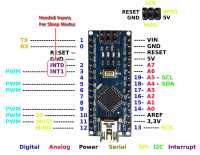
Again, Wiring and Programing needs to use Sleep Modes and Interrupts and above Nano wiring can't do that... Proof? Even ignoring Programing, View this and compare the two... His schematic has enough data to show can't just reprogram. Ignore "black boxes" connect to pins 7 8 & 9.
Can make this w/ DIP chip on UNO R3 and "burn" it to run on the Internal 8mhz clock. Then plug into Perf board or whatever. That alone saves power, space and wiring vs Nano used above Polling the HL switches constantly. 7805 & ACS712 uses power too but ACS712 can "sleep" under MCU controlling power to them. MCU pins can source ~ 20ma while ACS712 uses 10-13 ma each.
quote
Originally posted by pmbrunelle: I think that Ogre recognizes those who have gone off the deep end into the world of auto modification... and does not attempt to save those lost souls.
I don't think he has commented in my project thread either.
Yes, There are many threads I ignore. When I need a Horror Show, I'll just watch "The Car" (Apparently is on Netflix this month) or read "Christine" again. King movies stink but most stories and books are OK.
I won't comment on the use of a microcontroller based module for headlight motor control but it should be known that replacement headlight motor control modules have been reproduced and are still available. The Corvette module is exactly the same as the Fieros. As for the Gen 1 motors, you can construct the isolation relay from a std DPDT relay and a few diodes.
------------------ " THE BLACK PARALYZER" -87GT 3800SC Series III engine, custom ZZP /Frozen Boost Intercooler setup, 3.4" Pulley, Northstar TB, LS1 MAF, 3" Spintech/Hedman Exhaust, P-log Manifold, Autolite 104's, MSD wires, Custom CAI, 4T65eHD w. custom axles, Champion Radiator, S10 Brake Booster, HP Tuners VCM Suite. "THE COLUSSUS" 87GT - ALL OUT 3.4L Turbocharged engine, Garrett Hybrid Turbo, MSD ign., modified TH125H " ON THE LOOSE WITHOUT THE JUICE "
I won't comment on the use of a microcontroller based module for headlight motor control but it should be known that replacement headlight motor control modules have been reproduced and are still available. The Corvette module is exactly the same as the Fieros. As for the Gen 1 motors, you can construct the isolation relay from a std DPDT relay and a few diodes.
Ah yes. The GM parts bin thing. That's why the Fiero was not the car it should have been from day one. GM Execs: "You need to use crap we already have" Fiero Team: "COME ON MAN!"
Walker Texan, I admire your pinache, we do not have the luxury of making the car showroom original.. and sometimes must make do. I appreciate Ogres' quest for safety.. but as the cars age, there will be more and more compromises until we decide to dip them in amber and put them on the mantle. If you want to keep your work going into the embedded, sleep, and interrupt world, let me know and I will help you.. if you want to keep going, I want to assist. In order to keep things moving at 60 miles per hour, we will have to work together..
I wasn't going to post anything more on this because, let's face it, any time a egotistical jerk gets involved then any statement just feeds their ego. No way to get anywhere with that kind of jerk. So this will be my last post on the subject. No doubt the ego of the jerk will force another diatribe. If I stated the sky is blue on a sunny day he would HAVE to state that it is really azure. That is the nature of this kind of a__hat. And sad for the rest of us to have to tolerate bad behavior.
I felt it necessary to make this post because some very well-intentioned people have made "offers" to help me with this because they are under the wrong impression that need help with this. I Thank you kindly for your offers but frankly nothing could be farther from the truth. I welcome, and received some very good suggestions, one of which I have implemented as an improvement. The jerk's derogatory remarks consist of not just trashing my design but trashing my abilities and he could not be more wrong. Trashing my software and hardware skills that I suspect leave his in the dust. To be fair I don't know him so who knows, maybe he's really Bill Gates and Steve Wozniak writing together. Trashing me to boost his fragile ego is no excuse.
I stated that I was an expert in Test Equipment design and Root Cause Analysis because it is true. I stated that because that is why I determined the failure of my GM module as caused by the FET. The jerk just used that to make derogatory comments about experts. Sorry, that is uncalled for and incredibly rude and obnoxious. Until now I would never disrespect someone in an open forum and I have always expected the same from others but in this case an a__hat is an a__hat. For all I know he's an expert in something yet I would never disrespect him on his abilities or knowledge...until now. Shame I can't get the same respect.
So, here we go. He vents his spleen, so I can vent mine. If you make it to the end you'll find some good info.
1. Lead acid batteries self-discharge at a minimum rate of 5% per month and quite often 10% or more during severe ambient temperatures and only worsen with age. That's just a fact. The current my original design draws is less than the current drawn from the GM module. The reality is that if you don't DRIVE the car you are ruining the battery. If you aren't driving it on average once a week you are slowly killing the battery anyway and my circuit isn't going to make that any worse. If you are driving it then it is moot. If you disconnect the battery and only drive it once every couple of months you are ruining the battery. If you want to save the battery, drive the car or keep a trickle charger on it. The rest of his argument on the battery/wiring is pointless. Good grief, you do more DAMAGE to the car not driving it because the oil is become more acidic as it sits in the pan than if when driven. Wiring oxidizes worse when NO CURRENT is present; that's been proven by defense contractors/military for years because even a small current moves charges that negate some effects of oxidation even through the insulation which is porous to oxygen. Leaving a circuit unpowered, such as not driving, can affect the wiring more than using it. Contacts are even more susceptible because the wiping action of using switches and relays keeps them cleaner as well as passing current through them. I've done a LOT of HAST tests over the years where the results are different based on whether the unit under test was in operation or not. SO IF YOU WANT TO PROTECT YOUR BATTERY AND CAR THEN DRIVE IT AT LEAST SEVERAL TIMES A MONT. The current of my circuit won't change anything.
2. Polling of the switch in my design causing damage is absolute nonsense. Polling of the signals by the microcontroller is just that; the signals to the micro. The switch is in steady-state and there is a level-shifting buffer transistor between the switch and micro. The circuit isn't applying any current to the switch, the SWITCH is applying current tot he circuit in a steady state because the switch is HOT at ALL TIMES by GM's design. When the switch is in the off position it provides current to the GM module at all times. It is not fluctuating in any way. Polling has not negative outcome because the switch isn't even affected.
3. I could have designed this in many different ways. I have some Microchip 18F series microcontrollers sitting on my desk at a cost of less than $1 each that are more powerful than the AVR based Arduino and draw a tenth of the current. I could have used hall effect sensors from Honeywell that I also have that require 3uA to operate. I could have used an FPGA for this. All of those approaches, while making it very robust and low-power, would drive the cost or complexity above the abilities of many hobbyists. The whole point of this was to provide a simple design so the average Fiero owner could get a module for low cost. My design is easily built for less than $20 because all of the programming tools are free and none of the components are surface mount, like the hall effect sensors. I can solder tiny pitch devices, most hobbyists are nervous about doing that.
4. I didn't use "automobile" grade components simple because it isn't really necessary. The ACS714 is the auto version of the ACS712 yet it is only available in surface mount and I don't know of a cheap module available for it. Maybe there is now, I haven't looked in a while. The point is this design was intended to be in the front compartment where it is a lot cooler than the passenger compartment. Most auto grade components are designed to handle engine bay temperatures which will not be experienced in the front even though the radiator is nearby. The passenger compartment gets hotter because glass lets in light but is actually a reasonably good heat insulator. This lets the interior heat up with sunlight and retains the heat because glass is so good at insulating. The only reason it doesn't work as well as fiberglass is because the glass has to be quite thick to get a similar R factor. Point is, unless your car is black you probably aren't getting temperature anywhere NEAR the limit of the commercial grade parts I used, even in Texas. When it comes to cold, my friend in Minnesota doesn't drive his classic car in snow/ice/frigid temperatures because of road salt and possible damage to wrecks so I assume no one else is really concerned about driving in those conditions with my module design. Hey, if you're in Alaska, feel free to substitute better parts.
5. Claims that the Arduino NANO isn't up to the task is just nonsense. I have a whole suite of Arduinos that I've used on various projects and I like them because they are so easy to use. Most of my projects are for other people who ask me to design something for them and they want to understand it. I personally use Microchip parts for my own stuff and write the code in assembly because I like assembly. This project was an exception.
6. The Arduino NANO is often $5 or less. Hard to beat that. I chose it because people could buy several and not worry about damaging it while learning to use it.
7. The jerk seems to think I don't know anything about sleep modes, interrupts or power strategies. He would be absolutely and incredibly mistaken and I don't appreciate him implying I'm some idiot. Heck, one of my first projects out of college was on a team developing an 8080 based system for low-power management on some military equipment that ran from a small NiCd pack that actually required self-modifying code because large amounts of flash memory were not military specified parts back when the Fiero was first introduced. I KNOW what the hell sleep mode is. And interrupts. And low-power operation. I can also perform Tensor math because of my robotics experience and can convert from Geodetic to Geocentic positioning required for advanced navigation systems because I worked in that industry for decades. I am actually a retired Rocket Scientist where I was developing embedded test hardware, firmware and high-level software so I don't need you trying to "school" me on basic microcontroller technology. Just because you don't like it doesn't make it bad.
Still with me? OK. I was pleased to receive some input on my design and possible improvements despite the fact that mine original design has worked great for months and WITHOUT EVER NEEDING A JUMP START OR CHARGER. I usually drive it one day a week because I have antique plates on it and Texas doesn't allow for it to be my daily driver. I have my Veloster Turbo for that
Despite his crappy attitude and insults the idea of using an interrupt and power down modes had already occurred to me; I just didn't bother when I saw how much current the GM module used. Interrupts do tend to confuse neophytes, as do things like pointers in C. I went and made a new version that uses an interrupt and places the NANO in low-power mode. Simple mod, mainly because I already had it on the board and just wasn't using it. I made a new version of the code for it.
The interesting comment I received was the idea of using the Headlight switch to power the module and having a delay at turn-off so that the headlights could be lowered. I honestly didn't think about that because I was trying to mimic the GM module. I thought that was a brilliant observation. It took all of a minute to design in my head and another 10 minutes to implement it in hardware and maybe 10 minutes total to modifty the code. Works great. It's in my car now and it draws less than 1mA when the switch is off.
THAT'S what this forum is about! Not trying to humiliate people and push your weight around while proclaiming "I'm just helping because you're so stupid".
OK, so in the repository you will find three versions:
A: My original version which works fine. B: My interrupt and low power version if you want to use it or learn from it for a different project C: My power relay version which I recommend. Can't beat it for low power. Plus it is cool. I forget who suggested it but Kudos to you!
For the record, my designs are protected by the GPL as stated in the Arduino Repository. You may use it or modify it as you wish as long as I am given credit for the original concept and design, including hardware and software. I have been asked if it could be made and sold and my opinion on that is yes if you so desire provided ALL liability for use falls on you as the provider/seller. These designs are provided AS IS and with no warranty either expressed of implied.
Have fun. I won't be reading any more posts on this subject simply because I don't wish to continue the crap that the jerk does. Life is too short. I've rarely posted anyway, just read posts and his have always bothered me because he is so rude and unprofessional.
I save the perfect, bullet proof solutions for production level equipment. For prototypes and fun projects like discussed here, general solutions are fine. I type everything I post using my phone... this results in some omissions for the sake of my sanity.
I'd love to start a thread where people could talk about all the out of the box projects they are working on or have thought about.... with the rule that ideas should be discussed not torn apart.
WalkerTexan Thank you for putting the time and effort into this for the community. I appreciate more qualified people sharing and giving a spark of enthusiasm to move this hobby forward. Some people don't know how to be positive. THANK YOU AGAIN.
Cool idea. Thanks for sharing. I agree that construtive critiism is great. I don't agree with and wouldn't do a lot of the mods I see on here but I respect those that try something new and innovate.
Awesome idea, I am going to try and construct this and upgrade to some later model headlight motors. They are much easier to find brand new than the 84-86 motors. Thanks for putting in the time and sharing your idea!
I guess the statement of "if you have a good idea, 10 people have already thought of it" is very much true. I just discovered this post today.
If you guys remember my new headlight control system from my previous thread, they work almost identically to what is defined here.
I have been using my system daily with Gen 2 motor for almost 6 months now. Im going to start off with something. It works people. It really really works. I am so disappointed in the fact that some members ran off this intelligent forum member because they think they know better without actually trying it. The only real difference between my system and the one described here is that I have a manual override and disconnect switch. So I can always put the headlights up and disable the Arduino with just a toggle switch. I will say my code is a little tighter than the original but it isn't far off and he could have gotten there if more support had been shown.
As far as battery concerns, I disabled sleep mode and through it on my 86 while it was on the jackstand. I was able to start the car and then instantly shut it off for over a month without the Arduino killing the battery. It took 7 whole weeks before the battery became to low to start the vehicle. Is it a battery leech, yes, intrinsically it will drain the battery more than if it wasn't there but it's more than usable. Plus with my disconnect toggle if I am going to park for a long time I just turn the Arduino off from the front trunk.
I think I am going to release the schematics for people to try out. I am sorely disappointed with the way this man was treated. You guys overlooked a great idea before it even had a chance to blossom.
Again, "Arduino" can be used to run Gen2 Motors but Not this "Project..." This "I hate X thing" Goes way beyond Battery Drain or & no snubber in several areas. (Also seems He's remove all data from arduino.cc or they had other issues because link just above is Dead & Search won't help.)
Example & ⚠️ Warning: Anyone using relays listed here & related brands w/ sim PN is going to Burn them to run these motors directly. Just when depend how often used & more. You Hope When they Burns they Fail Open. If stuck Close then can/will Burn other more Expensive parts to Burn the car down.
I know "The Expert" & many others didn't read a data sheet because most "manufacturers" of them Don't publish the Data sheet + He repeatedly Claims the Relay handles 10A for this job. Only data available is @ amazon, ali ex, etc or marking on the Parts that are AC rating like most Switch/Relay parts to completely wrong! Worse, The rating on the Parts often don't match ratings for PN printed on them if you find datasheets.
Fact: Nearly All Relays/Switches Contacts Volts & Amp Ratings printed on them are for AC Only & 100% Resistive Loads like Standard Light Bulbs... AC or DC Inductive Loads Derate to 1/2 to 0 printed rating. In this case & very typical to ~ 1/3 of AC Resistive rating. Isn't just this relay, many 120/240VAC Switches burn out & quickly running garbage disposers, florescent tubes & related.
More Proof? By searching PN, I found only 3 Data Sheets for this part sold under many brands. One @ Elegoo is Songle that puts same relay in many "Kits" they sell. (Online direct or ISO of disks w/ many Kits.) 2 is link to Songle @ other site. 3'rd sheet is so poorly "copy/past" is missing a lot of data needed & ignored by anyone that knows facts like AC & DC contact rating are way different but some sheet say nothing for DC &or Inductive Loads.
⚠️ Warning: Relay listed above in Not Rated 10A for DC but 7A Max for Resistance Loads like light bulbs and 3A Max for Inductive Loads like any Motor. Read Data Sheet at https://datasheetspdf.com/d.../SRD-05VDC-SL-C.html
Summary: 3. ORDERING INFORMATION SRD XX VDC S L C
code:
Model	Nominal coil voltage  	Structure	Coilsensitivity	Contact	Form
SRD	03,05,06,09,12,24,48VDC	S:Sealed 	L:0.36W    	C:1   	Form C
7. CONTACT RATING Type FORM C Contact Capacity: Resistive Load 7A 28VDC, 10A 125VAC, 7A 240VAC Inductive Load 3A 28VDC, 3A 120VAC
I've tested Gen2 Motors In The Car with Hood Closed & pulls 4 to 5 Amps Running Up/Down. Motor in Stall at the End of Travel can suck 8 to 10 Amp for a few Micro Seconds if the Module Shuts Down normally. If module has problems & the Timer runs out, you have a motor in Stall that can pull even More Amps.
Caution: Songle products often don't match PN to Ratings printed on them. Same PN but end w/ A not C has small charges in rating in the sheet vs printed on it. Even if all are made as A that get a little better amps for some jobs but doesn't help for this application.
If you think Omron & others Well Known Brands will last longer for these small relays... Not for switching power to motors. Yes Omron make the "custom" relay for OE Module but only set Direction. (PN on Relay is Custom Job to meet GM Spec.) MOSFETs that handles motor amps Turn On/Off power to them. Omron G5LE is equiv to above only rated to 4 Amps 30 VDC for inductive loads.
[This message has been edited by theogre (edited 09-22-2023).]


 Now we can add Arduinos to the list of illegal things, including LED's, fire extinguishers, and brake upgrades.


 lol
lol

 More people w/o a clue making crap statements... Big surprise... Not.