The FSM and others are correct showing 2 coils in the gauge (Under "INSTRUMENT PANEL: INDICATORS CLUSTER") but missing a ceramic resistor on back of gauge. ~ 86Ω Resistor goes between 12v and input. Think is ½ of a voltage divider w/ the 90Ω sender and ceramic because gets warm to hot.
OP gauge in 85+ Fiero is same thing.
T-gauge has one too but wired different and different resistor value and don't have notes for that.
Set of gauge Coils are not = value but no notes on them.
All dash gauges often lie, a little to a lot, because often one to all contacts to them gets dirty, oxide layer, are loose, etc, adding or maybe reducing Total Ω ref to sender Ω. Example: You have large plugs to dash gets "dirty" but also 3 metal clips for each does same 2 x each clip... clip to board, clip to gauge "bolt." Gauge back Resistor "nuts" get "dirty" too doesn't help. (Don't clean the resistors! Can/will change value or wreck them and can't get new one but replace the whole gauge set.) If/when you loosen/remove the nuts, do not over tighten or will wreck the resistors. Only tighten until nut's ears are compressed.
FSM etc does same w/ other wiring w/ missing data. More so dealing w/ ECM for old cars. PCM BCM EDR ("Airbag Module") and other "boards" for other cars.
------------------ Dr. Ian Malcolm: Yeah, but your scientists were so preoccupied with whether or not they could, they didn't stop to think if they should. (Jurassic Park)
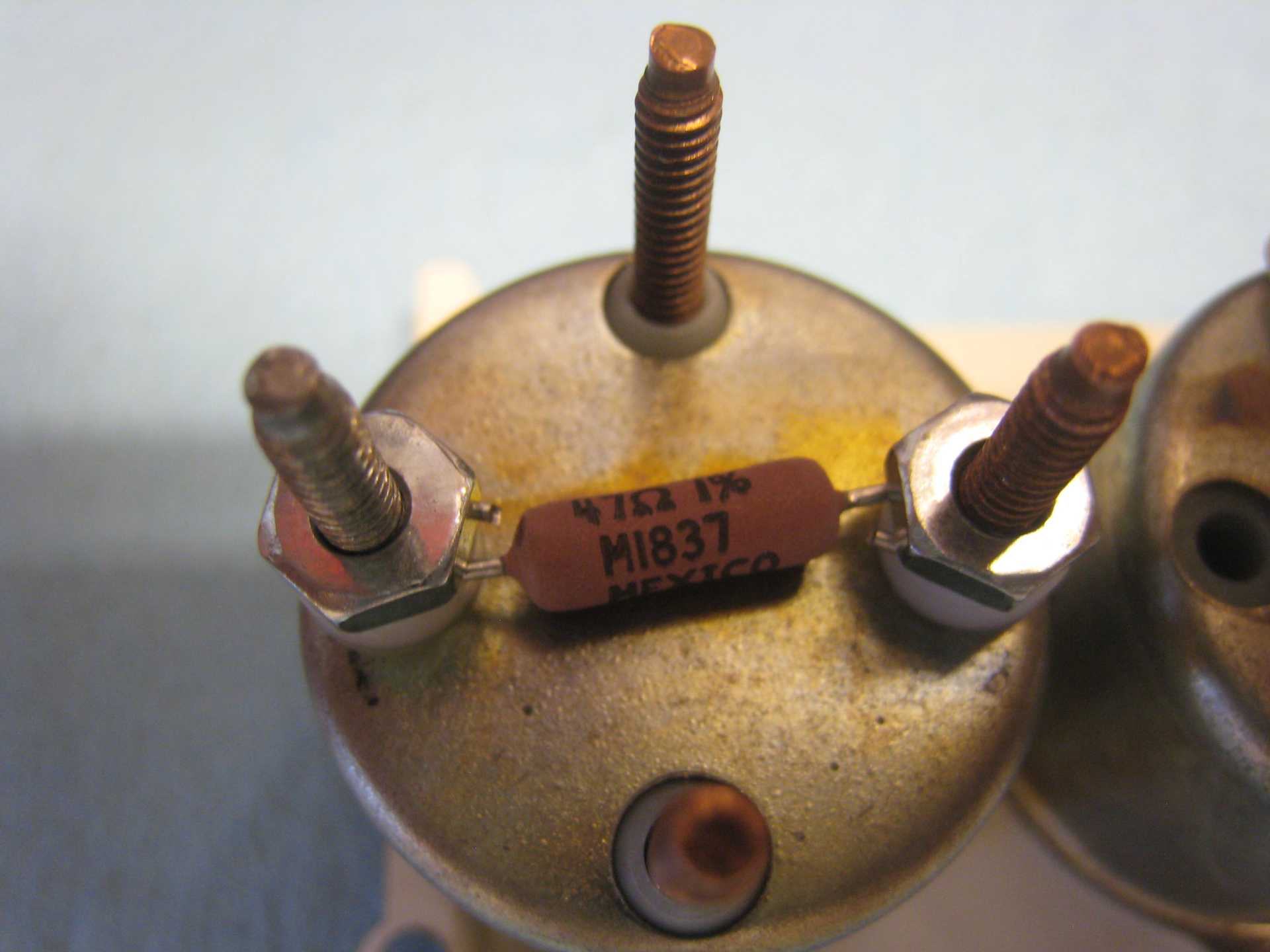
I measured 82.0 Ω on my fuel gauge resistor the other day. I don't know if 86 Ω was nominal, or was each resistor laser-trimmed to fine-tune each gauge, the resistive element then being covered over with a protective tape.
I wouldn't trust the stability of these old parts. The tachometer calibration depends on a resistor that appears to be the same style, and twice a year you have someone claiming that their engine is spinning at 4k RPM doing 60 mph.
quote
Originally posted by theogre: (Don't clean the resistors! Can/will change value or wreck them and can't get new one but replace the whole gauge set.)
Digi-Key has suitable replacement parts. I have the hardware to recalibrate my temperature gauge coming in tomorrow; I should be installing it tomorrow evening.
I doubt GM gave a crap about laser matching a resistor here... Fuel and OP gauge uses same pink color resistor. Carbon Resistors often have wide to very wide tolerance... Many Carbon and other resistors have 10% to 20% tol. 82 and 86 are w/in 5% of each other. If GM Target resistor was say 84Ω, both numbers are only ~ 2.5% off.
Then add many have cheap meters or good meters but have problems reading under ~ 100Ω for various reasons. Even worse < ~ 10Ω because probe resistance etc. and many including big names like Fluke don't have a way to "tare" the meter, IE the REL button is finally getting common.
Zeroing Ω of an analog meter wasn't just solving battery issues. Even Digital meters w/ REL function that many don't use it.
"recalibrate my temperature gauge coming in tomorrow..." Is a waste of time if you think numbers on Fiero T-gauge maters. Most cars had no numbers because setup was never made to be accurate w/ number gauges and use same setup.
Even when the gauge and sender are 100% good... Any problems between them can quickly make the gauge lie to you again and often sooner then later. Every connection, wires, etc for power and "data" have to work perfect plus everything on the frame and engine for grounding the circuit must also be perfect. The "12v" is not 12v when engine is running w/ 14 to 15v from the alt. ("perfect" alt output is 14.7v but rare to see that even @ alt out terminal.) Often isn't 12v when engine is off because Full Charge battery can be 12.6 to ~ 13.1.
Related issue is OP that often lies too. I've replace the sender, update to 88 sender, replace the gauge and resistor and more and still reads higher even with fix approx 45 and 90 Ω resistors to emulate ½ and full scale at OP plug. IOW ~ 45Ω resistor reads close or at full scale 99% of time.
The only sensors even close to accurate are ones for ECM w/ Ground and Regulated 5v power directly wired to the ECM. Even they have problems and why no long make the old style ECT.
The "Bad Tach" problems is often Not the resistors but devalued or dead caps. But many just follow the famous myth to fix can just put variable resistor. The "chip" uses RC pairs to set max swing (to match print job on front of tach) and pulse rate for given # of cylinders. Many old caps die in several ways not just crap caps made in China. Some times is the resistor "chip" or anything else after 20 - 30+ years of heat cycling from parking in sun.
The correct use of an Ohmmeter includes touching the probes together prior to use, to see if any parasitic resistance exists in the loop. If you don't have a REL button you can do the subtraction manually. But typically I see 0.1 Ω (on Fluke, BK Precision, and whatever else I use), so this is not a problem for taking measurements in the tens of Ohms. If you have more than this, you have a problem with your setup. For lower-resistance measurements, use a 4-wire setup.
Here my resistor is installed:
I'm not expecting perfection, but I am expecting better than what it was before! Before, the needle was either touching or in the red zone during normal driving. I don't know what went wrong, but anything is possible on a 35-year-old car. Maybe it's the aftermarket sender I used? Anyway, I will test this over the next week, comparing with the ECU's temperature reading.
To a first approximation, the fuel and temp gauge accuracy does not depend on the system voltage. For a single gauge, the needle orientation is determined by two coils, so as the system voltage varies, the currents in both coils remain proportional to each other. I guess you could add a regulator if you wanted to stabilise things more, but I don't think the complexity is warranted. I did not observe any difference in fuel gauge reading with engine running/stopped.
As for a quality tachometer restoration, you should replace both R and C. I agree that C should be changed for a film capacitor, but don't forget to change R as well.
[This message has been edited by pmbrunelle (edited 06-23-2020).]
PM, that looks good, but it would be super easy to make a PCB that the resistor solders to, and then bolts on like the old style. Let me know what part number you used and I will add a new PC board design to the next order when I get boards from China.. then hand out to anyone that needs them. I could even order them with gold without breaking the bank. Boards are now SOOOOOOO inexpensive.
Here is what I used for my temperature gauge solution: Resistor: Digi-Key ALSR3F-47-ND (I wrapped the leads around the studs and cut off the excess lead length) #6 nylon washer: Digi-Key RPC6806-ND Standard zinc-plated steel hex nuts, #6-32 (these were from my parts bin)
Take note that the fuel gauge resistor has some different requirements: 1. The plastic insulation around the base of the studs rises above the level of the metal can. The stock ceramic resistor includes counterbores to clear the insulation, so it can sit flat. A PCB should have large holes to clear the insulation, or should include counterbores/countersinks as appropriate. 2. When the fuel tank is empty, the fuel gauge resistor will see the full system voltage, whereas the temp gauge resistor sees a fraction of system voltage. So watch out for power dissipation.
For a PCB-based solution, I would not use a through-hole resistor like I used. Aside from being a non-standard value (for Fiero gauges), the solder joints on the bottom side would touch the metal can. Not good. So I would look at a single-layer PCB with surface-mount resistors. Possibly two in series/parallel to allow for better fine-tuning, and more power dissipation.
To keep things simple, I think you could build boards with a "GM default" resistance value, whatever that may be.
Then, people who want to fine-tune their gauge could do something like I did:
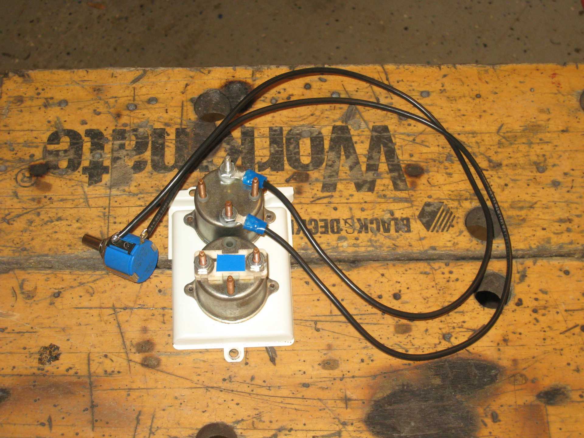
Replace the stock resistor with a multi-turn pot:
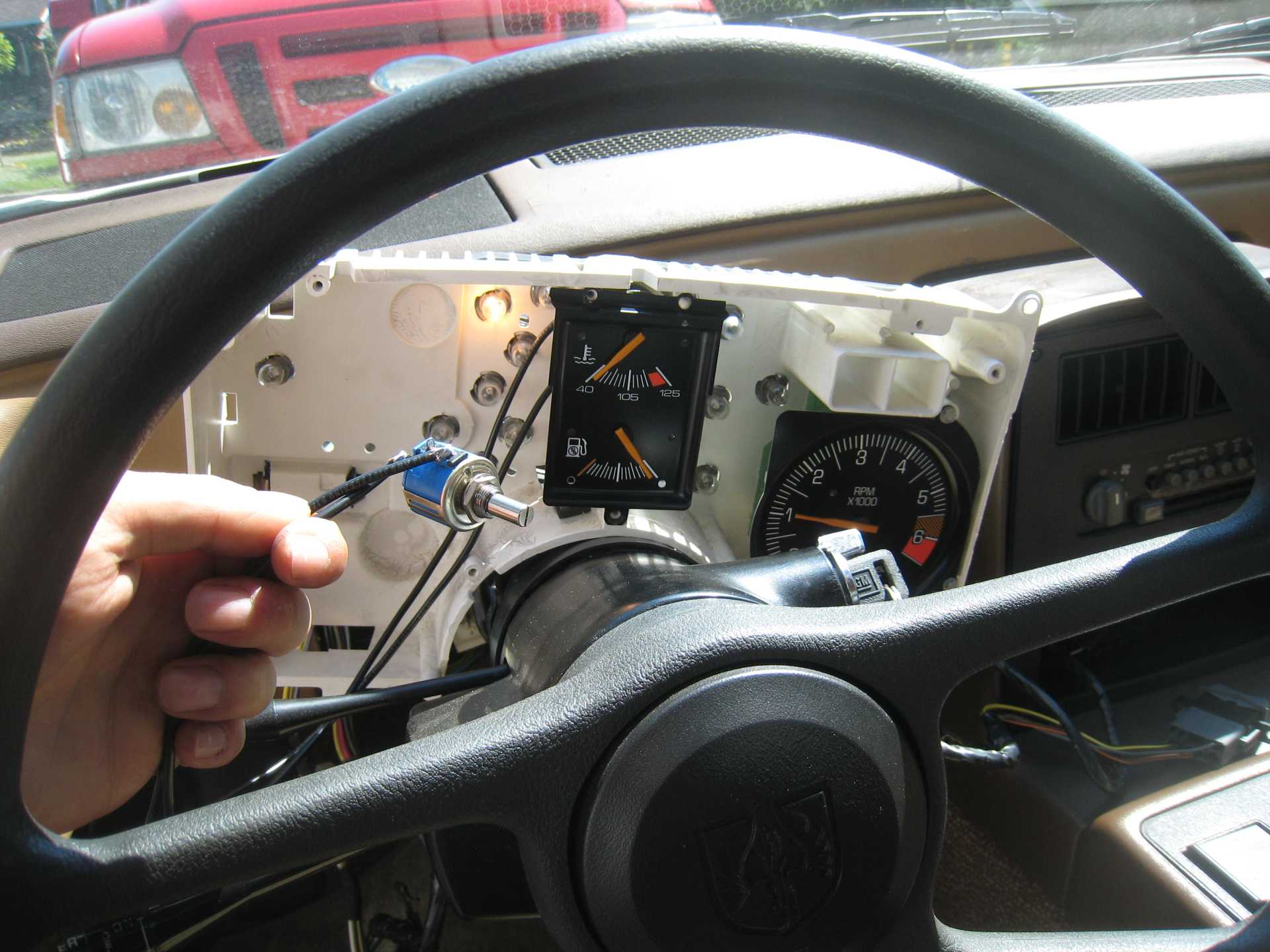
With the engine running, adjust the pot such that the gauge's reading agrees with reality:
For temp, use ECU data. For fuel, fill the tank to the brim.
Depending on the resistance that is found to be ideal, power dissipation could increase/decrease vs. the GM default resistance values, so I suggest putting the biggest SMT footprints that will physically fit, so as to give the most flexibility with regards to power dissipation. For folks who want to solder their own fine-tuned resistor values, it may be easier to hand them unpopulated PCBs.
[This message has been edited by pmbrunelle (edited 06-23-2020).]
I like just using the resistor but coat ends w/ Brake grease etc. Mix metal rot can happen from air moisture. you have "steel" nuts, copper or whatever bolts, tin whatever wire. Or can use GB Ox-Gard, Ideal NOALOX and others are in electric section of Lowes, HD, that works on more then Al wired resi/commercial stuff.
pc board, even w/ gold, can have same problem w/ OE or other hardware here. While now many PC parts are gold contacts... Many years ago most were Not and have gold on one and whatever on other often causes many problems like most early SIMMs and sockets.
[This message has been edited by theogre (edited 06-24-2020).]
Odd, I have a spare dash from a 2M4, and measured the ceramic resistor for the fuel gauge. I measure 88 ohms, with 4 wire kelvin. It has yellow paint. The metal coating where the nuts go is clearly worn away. And I see where the nylon insulation comes up around the stud where it enters the metal housing.. requiring a washer of some kind.The ceramic form on the bottom has recessed areas where the piece goes over the nylon.
I worked up a small board, single sided (traces cannot touch the metal meter housing), HASL (hot air solder leveling, tin-lead), where the 3W resistor leads lay down and solder on the surface of two pads.. (since leads cannot go through hole). It is not fully a rectangle, there is an ear on the upper left and lower right where the resistor pads solder (the body of the resistor is at an angle in the center). I will use a countersink to open up the holes in the bottom of the board slightly so that it slips over the nylon sleeves protruding through the meter housing. I like zinc plated 6-32 hex nuts with the built in washer, the original steel spring nuts rust and are part of the problem, and are too large in diameter anyhow. These bare boards will probably be in the ~50 cents range, so the resistor and shipping will cost far more when making them. I will order with the next group of boards soon.. along with the next version of the instrument back panel circuit board.
Ω in my 1st post was measured w/ a very old Fluke 77 and good probes....
Today I put the probes shorted get 0.3Ω
Took my new Craftsman Pro "Industrial" Model 82003 w/ REL and w/o tare get 0 to 0.4 put Fuke probes get 0 - 0.2, After Tare 0 - 0.1 (Auto range on.) FG Pink resistor is 83.3Ω on this meter. Temp resistor is 94Ω Seems Lite Green or Green Blue color.
Test again w/ new probes get so close to same doesn't mater.
The 87 and 86 I have are both the same resistance for both gauges. OP has same pink resistor. One handy measure 84.7Ω
Very possible other batches of gauges have different resistor to "tune" the batch. Maybe that's why GM doesn't mention the resistors anywhere available to the dealers or the public. If true you can't simply use same resistor on all of the gauges for whatever job and think will be better, likely will be worse.
FG resistor getting hot, more so w/ tank empty, means can't use "standard" pots unless you like "magic smoke." Most pots of all types handles < ¼ watt. Temp sender likely never sees close to 0Ω but Fuel and OP senders operates 0 - 90Ω all the time.
Yes, OE resistor is "countersunk" on meter side to clear plastic insulation and so the nuts hold the resistor and the coil inside tight to bottom of the back shell. W/o the resistor and nuts, Coils can move if you push the bolt in w/ little effort. EVEN IF you use 4 nuts, still needs "fiber" washers under to keep coils in place. OP resistor is same but weird nuts under them to make contact w/ tach board. Likely oversize the PC holes to clear coil insulation. (Not taking weird nut off.)
I did some experiments with a fuel gauge. I apologize, I am not great with whipping up graphics, which would be perfect here. There are three terminals on the fuel gauge, and inside are two coils. There are pictures on line showing this type of gauge on other vehicles. The coils are in series. The 12V connection is on the CCW (right) terminal viewed from back. The GND terminal is on the 6 oclock position. The gauge sender (0-90 ohms) terminal is on the CW (left) terminal. The ignition voltage goes to the 12 terminal, and there is a coil (coil 1) connected to the gauge sender terminal. It measures 86.7 ohms. There is another coil (coil 2) from the gauge sender terminal to the gnd terminal. It measures 102.8 ohms. The gauge sender of course connects to ground. The ceramic resistor, a yellow one measuring 88.1 ohms in my case, is in parallel with coil 1. Connecting resistors from the gauge sender terminal to ground gives us a moving needle. I cannot make every R value, but the 3 values that I have (plus 0 ohms) give realistic readings. I can remove the ceramic resistor and replace it with another dummy resistor, in increments of 10 ohms. When you change the ceramic resistor value, it clearly changes the span, not the zero. It has greater effect at the top, and almost none at the bottom. At the top, a 10 ohm change in value yields about a 1/8 tank change in indication. Raising the resistor value bumps the needle down. Lowering the resistor value bumps the needle up. With this info, and a gauge that is not damaged, one should be able to change the ceramic value until their gauge is calibrated. You might even be able to make it so that a full tank is actually on the full mark, not above it. This assumes that the tank sender is 0-90 ohms, which of course is not exact. I will make up a test device with resistors that allow you to connect to empty, 1/4, 1/2, 3/4, and full terminals for testing and calibrating gauges.
As look from back... FG pins are: 1. left insulated pin to sender 2. bottom non-ins pin to ground 3. right insulated pin to "12v"
I get: (new meter w/ REL used) 1 - 2 100Ω 1 - 3 85Ω 2 - 3 185Ω just to see others match actual Ω across 2 coils.
Pink Resistor is between 1 and 3 pins. Can say is is voltage divider w/ the sender, soft short to one coil, or whatever.
Tank sender is "0 - 90Ω" but isn't made very accurate. Tank "full" should = sender at 90Ω but often the "pot" have extra space. Many cars Gauges Empty is a bit above Tank Empty w/ E-pumps but not all. W/ "old" mechanical FP many cars had then Very close or at = . Old carb cars gauge said empty you aren't driving more then maybe 1 or 2 blocks.
IOW Can reach full or more is enough to many... Is a Bigger Problems when a gauge sticks or otherwise doesn't read last ~ ⅓ of tank.
Adjusting "full..." Ideally... Gauge Full is ~ = Tank Full IF you stop filling when Nozzle shuts off the First Time.
But that's making several assumptions by the maker... Many Problems, some main ones: Nozzles that work properly. Many don't. For Fiero... Make to work w/ Common Nozzles in 70's to early 90's. Most to All back then wasn't "Vapor Recovery" and other types that still causes problems for even New cars many times. (Most Station Pumps drops plastic bellows on the nozzles now but most are still VR systems.) Many Nozzles even back in 80's didn't quit fit the Fill Port on many cars. This cause the auto shutoff to trip often trip a lot w/ some cars. Other cars would late auto shutoff and cause spillage. Some stations have "high speed" pumps. This often have problems when you pull the handle all the way on. Fill at lower speeds, only pull handle to middle max. Many people "stuff the tank" and to the point even spill fuel trying to force last few drops. This causes way more problems then just a gauge reading over full.
Above are why you often see a gauge past "Full." But Ignore Many cars w/ Gauges w/ hard limits in them or BCM controlling gauges that may never register overfilling fuel tank. Most of those just stay at Full mark often for hours to days depending how much you drive.
If you "calibrate" any gauge then have you fix everything like clean up dash back board and gauge clips. Even then the calibration may not last long.
Side note: In many places, some of above reasons are why local fire codes and State "EPA" require nozzles that won't lock to disable auto fill. Many idiots "bypass" that and often spill more fuel at minimum. In many places, anyone "bypass" non locking nozzle can be ticketed etc. Many station can/will remotely shut down a transaction seeing pump flowing w/o you touching or move away because Station can get fined by Code, "EPA" or Fire Marshal offices if they ignore this.
[This message has been edited by theogre (edited 06-25-2020).]