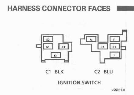
According the the Service Manual, this C1 plugs into the Ignition Switch itself. This car does not run at present - does it? You got work to do. I'm looking for a wiring diagram...
B3 is RED Power from fusible link A at the battery. (powers everything from START and RUN) I3 ORANGE supplies power to the the 30amp circuit breaker for the power windows in the fuse block. (HOT in RUN) TAN and GREEN wire have something to do with Key in Ignition Chime warning I think. (Green is ground for door open switches)
[This message has been edited by fierosound (edited 10-09-2018).]
Looking at 2 old GM schematics, I show the ignition switch is.. Red on B2 and B3 (2 wires?) 12V source. Brown on A is for accessory power Orange on I3 is hot in run, ignition Yellow on S is start Pink on I1 is hot in run, bulb test, and start So not sure about ignition switch.. But the headlights switch has.. Red on C Orange on A Yellow on D White on F Brown on E That is much closer to your colors..
According the the Service Manual, this C1 plugs into the Ignition Switch itself. This car does not run at present - does it? You got work to do. I'm looking for a wiring diagram...
B3 is RED Power from fusible link A at the battery. (powers everything from START and RUN) I3 ORANGE supplies power to the the 30amp circuit breaker for the power windows in the fuse block. (HOT in RUN) TAN and GREEN wire have something to do with Key in Ignition Chime warning I think. (Green is ground for door open switches)
Fierosound the car does run! I bought the car this way and have been sorting out the electrical which has been a chore. Headlights, parking, brake and signals all work. Hazards are still not working.
The car has a 3800SC series II with a sebring steering column. All the wires from the Black connector have a home in the sebring column except the 2 grn and tan wires. If they are for the Chime and door open switches I can remove them.
The Orange wire has been rerouted and I will have to see if is still powers the power window fuse blocks. As I would like to use for the windows I will be installing.
Looking at 2 old GM schematics, I show the ignition switch is.. Red on B2 and B3 (2 wires?) 12V source. Brown on A is for accessory power Orange on I3 is hot in run, ignition Yellow on S is start Pink on I1 is hot in run, bulb test, and start So not sure about ignition switch.. But the headlights switch has.. Red on C Orange on A Yellow on D White on F Brown on E That is much closer to your colors..
Chris, thank for the reply,
I do have two unaccounted wires coming out of the bundle of wire that feed the ignition. an orange and red. These are smaller in gauge and might be the Red on C and Orange on A that you are referring to?
This is the way I found the wires... not the type of work I would do
[This message has been edited by Simple Man (edited 10-09-2018).]
Its so hard to tell from this end.. where on the car are you taking pictures?
The picture is taken just to the right of the steering column. all the ignition wires and the twisted red and orange are coming out if the same bundle of wrapped wires. I have an 88 parts car and was able to confirm they all come from the same bundle/harness
The car has a 3800SC series II with a sebring steering column. All the wires from the Black connector have a home in the sebring column except the 2 grn and tan wires. If they are for the Chime and door open switches I can remove them.
Aha... that's why everything looks so messed up in that picture (cut wires everywhere).
[This message has been edited by fierosound (edited 10-10-2018).]
The two small green wires are the ground for the bulb test circuit that causes the temp Gage to peg when you turn the key ON. The tan wire is your brake warning power feed that goes to the bias valve and emergency brake lever.
The two small green wires are the ground for the bulb test circuit that causes the temp Gage to peg when you turn the key ON. The tan wire is your brake warning power feed that goes to the bias valve and emergency brake lever.
thanks for the information, although I now have two different opinions. Under each repsonse I think I do not need the 2 grns or 1 tan wire connected.
The temp gauge is being handle in a different manner.
Not sure what the bias valve wire function is but the car has a wilwood system with proportioning valve etc.
Is the E brake wire to signal that the e brake is still on? I am using a different brake handle and haven't thought about much about that function.
For now I will tag the wires and leave in place.
Thank for the replies! the comments are very useful in sorting out this mess
Grounding the tan/white wire turns on the BRAKE light on the cluster. The lever has a switch that provides ground when ebrake is engaged. Low pressure in the brake circuit allows the spool to move far enough to trip a grounding switch on the OEM bias valve.
The two green wires provide GROUND for the BULB CHECK function of the ignition switch. Pontiac made an error when wiring the Temp Gage and the HOT light, proding the bulb check ground to the Gage, rather than the light.
What I posted is not my opinion, it is the factual way that the vehicle is wired.
[This message has been edited by olejoedad (edited 10-10-2018).]
Grounding the tan/white wire turns on the BRAKE light on the cluster. The lever has a switch that provides ground when ebrake is engaged. Low pressure in the brake circuit allows the spool to move far enough to trip a grounding switch on the OEM bias valve.
The two green wires provide GROUND for the BULB CHECK function of the ignition switch. Pontiac made an error when wiring the Temp Gage and the HOT light, proding the bulb check ground to the Gage, rather than the light.
What I posted is not my opinion, it is the factual way that the vehicle is wired.
olejoedad Thanks again! I think I will keep the tan white wire and get that to work with my system. I believe the hand brake I am using has a switch or I might possibly have that part on my 88 fiero, will have to check it out and see how it functions.
B2 - Red from fuse link A battery power B3 - Red from fuse link A battery power A - brown, switched power to radio and battery fuse (hot in RUN) I3 - Orange, switched power to WDO circuit breaker, Fan E fuse, HTR AC fuse (hot in RUN) S - Yellow, Start signal to solenoid (hot in START) I1 - Pink, switched power to TBI fuses, Turn B/U fuse, ECM fuse, Gage fuse, IGN coil via fuse link H ( hot in START, BULB TEST, RUN G2 - tan/white, ground in bulb test for brake warning indicator G1 - lt green, ground for temp Gage in bulb test (GM wiring error)
[This message has been edited by olejoedad (edited 10-11-2018).]
B2 - Red from fuse link A battery power B3 - Red from fuse link A battery power A - brown, switched power to radio and battery fuse (hot in RUN) I3 - Orange, switched power to WDO circuit breaker, Fan E fuse, HTR AC fuse (hot in RUN) S - Yellow, Start signal to solenoid (hot in START) I1 - Pink, switched power to TBI fuses, Turn B/U fuse, ECM fuse, Gage fuse, IGN coil via fuse link H ( hot in START, BULB TEST, RUN G2 - tan/white, ground in bulb test for brake warning indicator G1 - lt green, ground for temp Gage in bulb test (GM wiring error)
Thank you! All the wires from the ignition switch identified.
The red twisted with the orange, in my picture, have no power with the key in the on or off position.
Orange may go to fuse box. Red may go to BJT under C500.
as suggested I will try to trace the wires when I get home tonight and see when comes up.
I did figure out what the twisted orange and red wires belonged too. They are part of the wiper circuit . THe connector for the wiper cicrcuit had only 1 wire attached and it was hot. THis wire was traced back to the Fuse block and the space for the wiper mototr
From the wiring diagram I can see the wires that were use purple grey etc.
So making some headway on this mess!!
[This message has been edited by Simple Man (edited 10-12-2018).]