Pennock's Fiero Forum
  Technical Discussion & Questions
  Valve rocker-to-stem contact sweep (1.52 roller tipped rockers)

Post New Topic  Post A Reply
Email This Page to Someone! | Printable Version


next newest topic | next oldest topic
Valve rocker-to-stem contact sweep (1.52 roller tipped rockers) by pmbrunelle
Started on: 04-29-2018 12:20 AM
Replies: 5 (223 views)
Last post by: pmbrunelle on 04-30-2018 01:27 AM
pmbrunelle
Member
Posts: 4661
From: Grand-Mère, Québec
Registered: Sep 2008


Feedback score: N/A
Leave feedback


Total ratings: 63
Rate this member

Report this Post04-29-2018 12:20 AM Click Here to See the Profile for pmbrunelleSend a Private Message to pmbrunelleEdit/Delete MessageReply w/QuoteDirect Link to This Post
I'm at the stage of my engine project where I need to determine my pushrod length.
So I bought adjustable checking pushrods, in order to tweak the pushrod length such that the rocker is pushing in the sweet spot of the valve stem.


This engine has a hydraulic lifter camshaft. Since hydraulic lifters won't work correctly without the engine running, I bought a pair of solid lifters for setup/measurement purposes.
The solid lifter and the hydraulic lifter don't have quite the same height (tappet face to pushrod cup distance).
When I determine the pushrod length I need for use with the hydraulic lifter, I'll compensate for the difference between the two lifter types.

Anyway, so I adjusted the pushrod so the sweep of the roller is centered around the middle of the valve stem.
Lash is near zero, 0.005" at most.

I have Comp Cams 1.52 roller-tipped rockers.

Pictured is #2 the exhaust valve.

Base circle:


Full lift:


Is this a normal-looking sweep?
Should I shift the sweep over a little to the intake manifold side, so that at max lift (which is max spring force), the rocker is pushing slightly closer to the middle of the valve stem?

Another question: is it normal that my 5/8" hex socket is rubbing (binding sometimes) on the rocker when I try to turn the adjustment nut? I'm thinking that I may have to buy a cheap socket, and grind material off the outside diameter so it fits better.
IP: Logged
PFF
System Bot
Blacktree
Member
Posts: 20770
From: Central Florida
Registered: Dec 2001


Feedback score:    (12)
Leave feedback


Total ratings: 350
Rate this member

Report this Post04-29-2018 10:34 AM Click Here to See the Profile for BlacktreeClick Here to visit Blacktree's HomePageSend a Private Message to BlacktreeEdit/Delete MessageReply w/QuoteDirect Link to This Post
Looks like you nailed it. The problem is, when you switch to the hydraulic lifters, that's going to change. But it should be close enough.
IP: Logged
olejoedad
Member
Posts: 20119
From: Back home again in Indiana
Registered: May 2004


Feedback score: (5)
Leave feedback


Total ratings: 201
Rate this member

Report this Post04-29-2018 01:57 PM Click Here to See the Profile for olejoedadSend a Private Message to olejoedadEdit/Delete MessageReply w/QuoteDirect Link to This Post
You can set this up using hydraulic lifters. Initial valve lash settings sink the plunger in the lifter to midpoint of plunger travel. Oil pressure when engine is running provides extra " cushion" at high RPM. When rotating the engine by hand to set up initial positioning, hydraulic lifters work just fine.....
IP: Logged
viperine
Member
Posts: 1401
From: Pittsburgh, PA, USA
Registered: Feb 2015


Feedback score:    (6)
Leave feedback

Rate this member

Report this Post04-29-2018 02:35 PM Click Here to See the Profile for viperineSend a Private Message to viperineEdit/Delete MessageReply w/QuoteDirect Link to This Post
You can also disassemble a lifter and insert washers inside of it to simulate lifter height at full pumped up (running) value.

This is the method I used to determine pushrod length on my 406 sbc build. It's been a while and I am sort of fuzzy on how I pulled it off, but i do know I only needed to use one spare lifter for the whole process.
IP: Logged
pmbrunelle
Member
Posts: 4661
From: Grand-Mère, Québec
Registered: Sep 2008


Feedback score: N/A
Leave feedback


Total ratings: 63
Rate this member

Report this Post04-30-2018 01:09 AM Click Here to See the Profile for pmbrunelleSend a Private Message to pmbrunelleEdit/Delete MessageReply w/QuoteDirect Link to This Post
 
quote
Originally posted by Blacktree:

Looks like you nailed it. The problem is, when you switch to the hydraulic lifters, that's going to change. But it should be close enough.


Good to know that it looks OK by your eye.

Actually, figuring out the pushrod I need with the hydraulic lifter is pretty simple once I have it figured for the solid lifter.

Throwing out random numbers here as an example:

Solid lifter height (pushrod cup to bottom face): 1.200"
Hydraulic lifter height (pushrod cup to bottom face, with plunger preloaded 0.040"): 1.100"

Pushrod length needed for solid lifter (determined by trial and error): 6.158"

Pushrod length needed for hydraulic lifter:
The hydraulic lifter is 1.200" - 1.100" = 0.100" shorter than the solid lifter.

Therefore, to make up for the shorter height of the hydraulic lifter, the pushrod should be lengthened by 0.100".

Pushrod length for hydraulic lifter: 6.158" + 0.100" = 6.258"

Again, these were random numbers. I just chose them to explain the general procedure for adjusting a pushrod's length depending on the lifter used.

 
quote
Originally posted by olejoedad:

You can set this up using hydraulic lifters. Initial valve lash settings sink the plunger in the lifter to midpoint of plunger travel. Oil pressure when engine is running provides extra " cushion" at high RPM. When rotating the engine by hand to set up initial positioning, hydraulic lifters work just fine.....


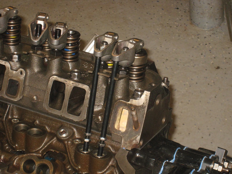
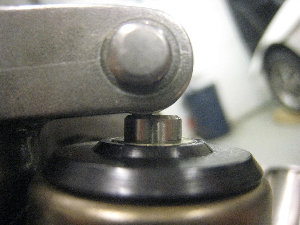
When turning over the engine by hand, the valve won't start opening until the plunger has bottomed out in the lifter. So you won't see as much valve lift as when the engine is running.

 
quote
Originally posted by viperine:

You can also disassemble a lifter and insert washers inside of it to simulate lifter height at full pumped up (running) value.

This is the method I used to determine pushrod length on my 406 sbc build. It's been a while and I am sort of fuzzy on how I pulled it off, but i do know I only needed to use one spare lifter for the whole process.


I actually started doing that with the least-worn of my old lifters; it was a bunch of fooling around though. Then, when I tried to weld the plunger to the lifter body, I was having a hard time welding the plunger without damaging/affecting the pushrod cup.

So buying a pair of $3 solid lifters seemed like a no-brainer.

Obviously, the method can be made to work.
IP: Logged
pmbrunelle
Member
Posts: 4661
From: Grand-Mère, Québec
Registered: Sep 2008


Feedback score: N/A
Leave feedback


Total ratings: 63
Rate this member

Report this Post04-30-2018 01:27 AM Click Here to See the Profile for pmbrunelleSend a Private Message to pmbrunelleEdit/Delete MessageReply w/QuoteDirect Link to This Post

pmbrunelle

4661 posts
Member since Sep 2008
 
quote
Originally posted by pmbrunelle:
Another question: is it normal that my 5/8" hex socket is rubbing (binding sometimes) on the rocker when I try to turn the adjustment nut? I'm thinking that I may have to buy a cheap socket, and grind material off the outside diameter so it fits better.


The conclusion to this part of the story is that I bought a 5/8" hex socket from Canadian Tire, and I turned down the OD on the lathe. It's much easier to turn the rocker stud nuts now without the rubbing. I probably went a bit too far with the material removal; if the socket breaks, I won't remove as much material next time.

Sockets are apparently pretty hard steel, because my HSS cutter just got chewed up. With carbide, I was able to cut into the socket.
IP: Logged

next newest topic | next oldest topic

All times are ET (US)

Post New Topic  Post A Reply
Hop to:

Contact Us | Back To Main Page

Advertizing on PFF | Fiero Parts Vendors
PFF Merchandise | Fiero Gallery
Real-Time Chat | Fiero Related Auctions on eBay


Copyright (c) 1999, C. Pennock