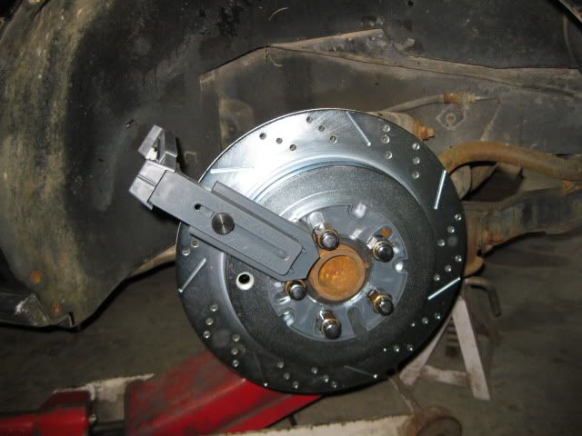
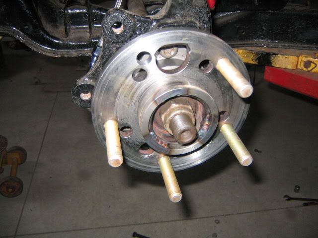
My 13" brake kit does not clear my current 16x7 wheels, so I am looking to upgrade to some 17's at the minimum. I am probably going to upgrade to the 4 3/4" pattern front/rear at the same time to improve CV joint strength and allow use of cheap oem Corvette wheels (C4, C5 or C6). So I ordered a Percy's Wheel Rite Wheel Fitment Tool (#01201) and used it to check for clearances front/rear.
Starting with the front: The majority of C4/C5 wheels are 8 1/2" wide, so I set the tool for 17" wheel, 8 1/2" wide and then adjusted the back spacing to get the inner edge of the wheel edge flush with the top of the fender (6" of backspacing or 44.5mm offset). Then checked clearances with the suspension at ride height and sitting on the bump stop (front spring/shock were removed). At this setting there is some very light contact with the inside of the rim and the rear flange of the control arm. The tool has a sharp corner and the wheel will be rounded, so it might fit with some minor flange trimming.
The only problem with the front is the C4 wheels come with a 56mm offset and the C5's are 58mm... so I need to reset the tool to this size and see if all I need to do is clearance the weld flange to make them fit.
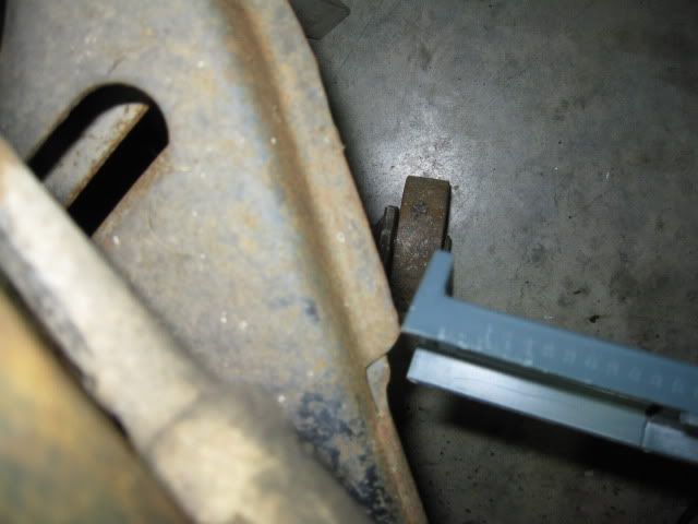
For the rears, I kept the tool setup for 17" 8 1/2" & 6" of back spacing and checked them. The tool has a slight interference with the strut mount/upright ear and the inner edge of the wheel tool is nearly flush (might stick out 1/8") with the top of the rear wheel well.
One of my main goals with this exercise is to maximize wheel width under a stock bodied fiero. From checking the 17" 8 1/2" setup, I noticed that going to 18" in the rear would give me more depth to play with. So I adjusted the tool to 18" diameter, 10" wide and 7 1/2" back spacing. This allows the tool to clear the strut/upright and the only interference is with the trailing link (which can be reworked or bushed from the upright to clear).
The 18" x 10 makes me much happier, but still wanted more... The 88 with the 3 link setup, makes it pretty simple to shorten the lateral links and pull the wheels inboard some. At ride height, there is about 1 1/2" between the back of the strut and the frame rail. At full droop this clearance is about 1 1/8"
So I "should" be able to shorten the lateral links by 1" and run an 18 x 11 wheel in the back... Assuming there is enough slot to get the wheel to zero camber with the shorter lateral links.
A quick check on ebay shows a 17 x 8.5 and 18 x 10.5 in the same C5 style wheel that can be purchased new for $601 for all 4... need to go and double check the 17 x 8.5 with the 58mm offset.
I reset to the tool for the C5 17 x 8.5 wheels at the 58mm offset and came up with these minor issues. The interference is at maximum lock and the interference is isolated to a couple of flanges on the lower a-arm. I can grind these flanges for the needed clearance and then reweld the seam. From what I have seen so far, it looks like the 17 x 8.5 C5 wheels are a go for the front. Once I get the wheels, I can verify what the actual clearance/interference issues are vs. what the tool says.
The rear with 18 x 10.5" C5 wheels should work as well... close enough I want to verify with an actual wheel.
It will probably be a few weeks till I have the $$ to purchase the C5 wheels. I am hoping I can get them used off craigslist now that I know what I am looking for.
Nice pics. I've been in the middle of figuring out what 17" front / 18" rear wheel/tire combo is going to work on my 355 kit for quite some time now, trying to avoid the need for custom wheels and deciding what's going to clear. That tool might've come in handy (though I've found my drawings to be quite useful too).
I'm not sure what overall tire diameter you're thinking of using, nor whether you're planning a suspension drop, but one additional area that I've found in need of consideration is the clearance of super wide tires with the underside of the rear upper framerails in jounce, especially with a spring drop. Those 11' wide wheels are going to need some seriously wide rubber, and unless you're planning on tires with a seriously low profile, the clearance under that framerail can become an issue. The front doesn't seem to as critical, but it can be, depending on the magnitude of the drop.
What's your plan for the 4-3/4" front and rear bolt pattern? Are you just redrilling the fronts? What about the rears... is someone making a one piece flange or are you thinking of welding up a larger ring on the stock flange and redrilling it? Which CV joint are you referring to? So many questions!
For the tires, I am thinking 245/40/17's up front (24.7" diameter - replacing the 245/45/16's that are 24.6") 295/30/18 in the rear (25.0" diameter - replacing the 245/45/16's as well). I would love to run some 315/30/18's... just don't think they would fit.
CTFieroGT87 is the one who corrupted my brain with the C5 wheels. His 87 (with 88 suspension front/rear) is running the C5 18/19 setup. I think the wheels are a bit too tall for my liking, which is why I am trying to stick with the 17/18 setup: https://www.fiero.nl/forum/Forum1/HTML/067237.html
you can always spend more money and buy a set of the HT motorsports tubular LCA to see if that helps up front. http://www.westshorefabrica...KitCarSuspension.htm As for the rear, I am running a set of the HT Motorsports hex alum rods with the hiem joint ends http://www.westshorefabrica...Suspension_Links.htm and they offer the ability to move the hub in/out about 1/4 inch or so per side to square things up. I always wanted to know if the HTM front tubular arms were a good buy or not.
Loving this thread
rob
[This message has been edited by qwikgta (edited 01-23-2012).]
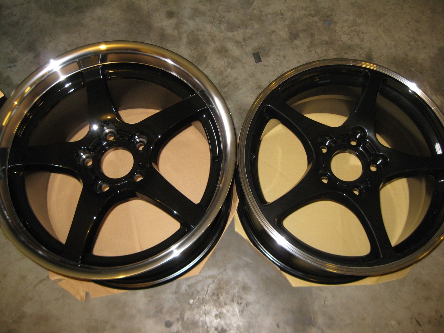
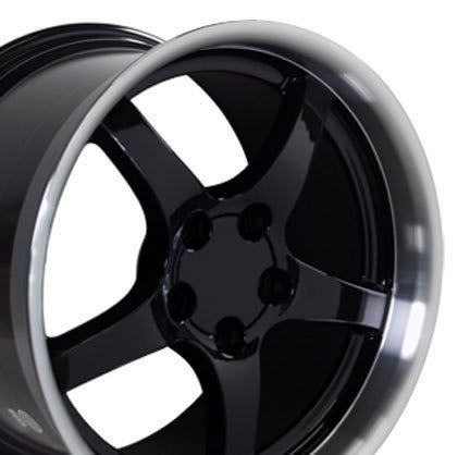
Ordered one 18 x 10.5 and one 17 x 8.5 today. I will use these wheels to confirm fit before purchasing the other side. They have a polished lip and black powder coated centers. The black should really show off the 13" rotors and my colored calipers.
This is the rear one:
[This message has been edited by fieroguru (edited 02-11-2012).]
I was more concerned with overall backspacing (7.95 for rear, 7.03 front). The rears will be within 1/8" of the strut body and the fronts will probably need to have the pinch welded flange on the lower a-arms clearanced and welded flat about 1/2" for lock to lock turning, or that is how I think they will fit...
You probably want the top view, but here's a rear view of how a generic 17 X 8.5 (ET 58) should fit. Good front spacing although it looks like they will probably stick out a couple mm further than stock wheels. Technically, they would have to have an offset of 63 mm to have the outer rim at the same location as stock. Notice how they'll drop the stock scrub radius in half from 40 mm to 20 mm.
Let me see how quickly I can conjure the top view too.
Nice work guys, I have been thinking about putting C5 wheels on mine as well. Haven't had time to go through the process, I'm following your progress with this.
Not wanting to impose, but if you happen to have the time to put a 235/40/17 tire on the front and do the back setup (wheel bearing is 2mm thicker than stock fiero) with a 305/30/18. I am hoping the curvature of the inner lip of the wheel will clear the strut body... if not, I will probably redo the rear wheel bearings and not remove the 1/8" of material that I did.
My Fiero with the LS4/F40 combo should have a weight distribution of 43/57 and this tire combo is very close to that balance... just do not know if the rear tires will clear the strut or if I will have to pull the wheels in some to keep them under the body.
[This message has been edited by fieroguru (edited 02-12-2012).]
Here are the drawings starting with the front. I raised the knuckle height 50 mm, then set the control arms to match the new locations of the ball joint holes in the knuckle, then added the new rims and tires (I used the wheel and tire sizes you specified and got the dimensions using the tire calculator at this website: www.rimsntires.com/specs.jsp ) which then gave a new ground location, ground clearance and center of gravity height. You'll notice that the ground clearance doesn't simply drop by 50 mm because the change in tires and wheels affects that measurement. You'll probably need slotted upper ball joints to make this work because if you look closely, the upper ball joint isn't in the hole on the knuckle correctly in order to keep the camber at zero. You'll also notice that the track width has changed as well due to two things: the new wheel width and the raised control arms which both move the center of the tire patch closer to the center of the car. This is beneficial for the scrub radius which is now about 14 mm instead of the stock 40. One last note, I left the rolling tire diameter the same as the overall tire diameter rather than accounting for some deformation due to the weight of the car since the very low profile tires wouldn't flex much.
Here are the rear drawings. I followed the same order of reconstruction as above except that I raised the knuckle 35 mm added 2mm thickness to the bearing flange (red bar) then rotated and added everything else to match up. I added your custom lower knuckle adapters (57 mm drop) to show how they will affect the angle of the lower lateral links and the trailing link. I used an arbitrary wheel profile but you can see how you are right to be concerned about the clearance at the strut and the trailing arm mount at the lower end of the knuckle. Obviously the spring is not a coilover so you shouldn't have an issue there since yours is a coilover. There may be a few other observations I've missed, but it's getting late. Let me know if you have questions.
(Edited to add new CofG height on front suspension drawing rear view)
[This message has been edited by Bloozberry (edited 02-13-2012).]
Thanks Blooze! The drawings look great and it looks like the wheels will just barely fit (with a few minor tweaks) as anticipated. The pictures really show how little room there is in 3 key areas in the rear.
The rear tires are probably sticking out past the body a bit as shown. I plan to shorten the lateral links some to pull the wheel back it, but this will also reduce the clearance between the tire and strut, so I can't move it much. My rear coilovers will be mounted to the weld bead of the stock spring perch on the strut. There just isn't enough room for the coil over sleeve, adjuster or spring anywhere alongside the tire.
The lateral link relocation brackets will be made once the actual wheel shows up. In the drawing, it looks like they hit the wheel, and that rear trailing link bushing is rubber and will move around a bit. Probably will need to reduce the lowering of the lateral links some.
Since moving the wheel inboard to pull the outer edge in flush will further reduce clearance to the trailing link, it will either need the rear mount shimmed inboard, or it will need remade with an offset build in for tire clearance.
The potential interference issues on the front are when the suspension is at full lock with the back side of the rim potentially hitting the flange weld seam on the a-arm. When the front wheel arrives, I will install it and verify if this is an issue, or just really, really close!
For the front suspension, I normally extend the upper a-arm attachment slots outboard on the crossmember to allow more range of adjustment for the camber setting when lowered. I am also curious as to what placing a 1" shim between the crossmember and upper a-arm mounting (and raising the rear). When lowered by springs or lowering ball joints, the upper a-arm ends up at a pretty severe upward angle. The 1" spacer would help the angle (and improve adjustment range), but need to check its impact on bump steer. The 1" bracket would also provide a handy place to install some jack screws between the body and a-arm to help make small adjustments to fine tune the front suspension alignment.
The drawings are very helpful! Thanks again Blooze!
For the front suspension, I normally extend the upper a-arm attachment slots outboard on the crossmember to allow more range of adjustment for the camber setting when lowered.
Of course! What was I thinking? There should be enough play in the upper control arm slotted mounts to accommodate zero camber since I kept the arm centered in the slots for the drawing having forgotten about the slots.
guru, looking at the rear view of the rear suspension, in regards to shortening the lateral links, it looks like there is room to move the "bolt tube" out, in the direction of the rotor maybe an inch. this might give you what you need without shortening the arms?
guru, looking at the rear view of the rear suspension, in regards to shortening the lateral links, it looks like there is room to move the "bolt tube" out, in the direction of the rotor maybe an inch. this might give you what you need without shortening the arms?
True, but I have adjustable rod end lateral links that will make this change quite simple.
I am also curious as to what placing a 1" shim between the crossmember and upper a-arm mounting (and raising the rear). When lowered by springs or lowering ball joints, the upper a-arm ends up at a pretty severe upward angle. The 1" spacer would help the angle (and improve adjustment range), but need to check its impact on bump steer. The 1" bracket would also provide a handy place to install some jack screws between the body and a-arm to help make small adjustments to fine tune the front suspension alignment.
That's an interesting idea. I've seen more than one instance where this bolted joint fails resulting in movement of the upper control arm shaft with respect to the front crossmember. I'm sure you can imagine the resulting camber and toe changes.
The original designers put serrated teeth on that shaft where it contacts the cross member much like the bolted joint between the rear upright and strut. I don't understand the theory of designing a bolted joint in that manner considering that frictional force is independent of surface area. What I have seen with with bolted joints of this nature is that over torquing the fasteners can exceed the yield strength of the material because of the reduced surface area. Exceeding yield strength is of course a sure way to lose your clamp load on your bolted joint. Considering that the only torque wrench I have ever seen in an alignment shop is bubba with a breaker bar I'm sure that these are a prime candidate for over torquing.
That's a long winded way of saying that this might be a good opportunity to look at improving the bolted joint or eliminating it. For improvements you could look at adding fasteners outside the plane of the existing fasteners (looked like there was a little room looking at the suspension I recently tore down but likely that room would not exist once assembled in the car). To eliminate the joint you could weld your spacer to the cross member and rely on your jack screws and/or ball joint for camber adjustment.
[This message has been edited by Jefrysuko (edited 02-13-2012).]
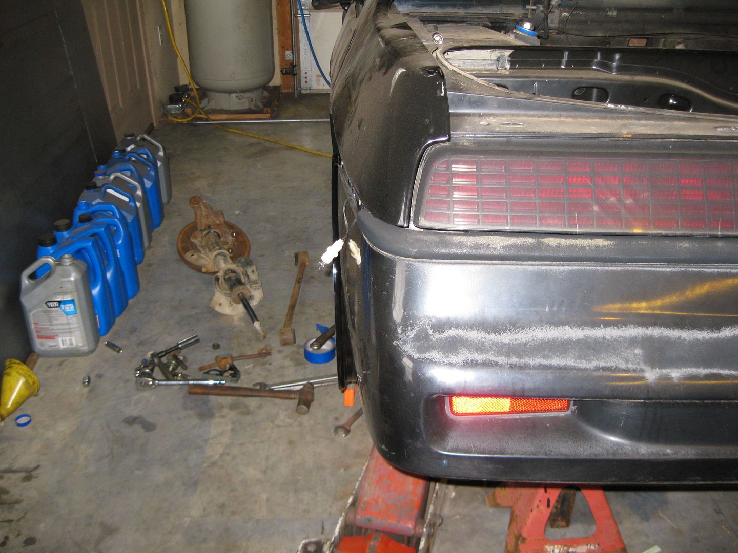
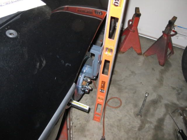
I was able to spend a few hours today test fitting my wheels.
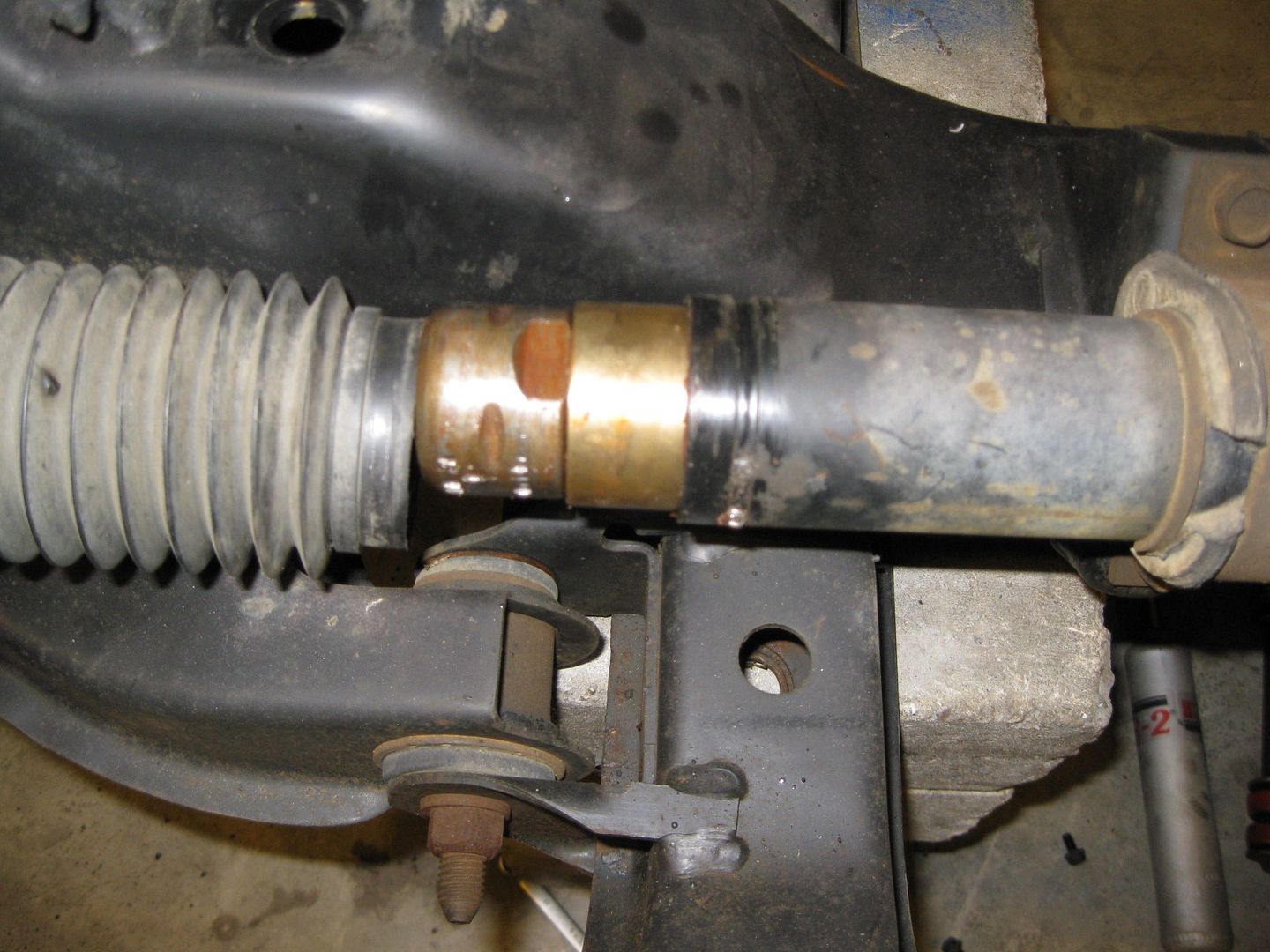
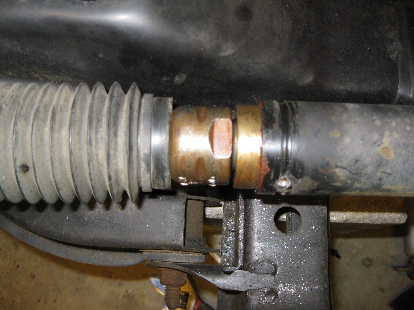
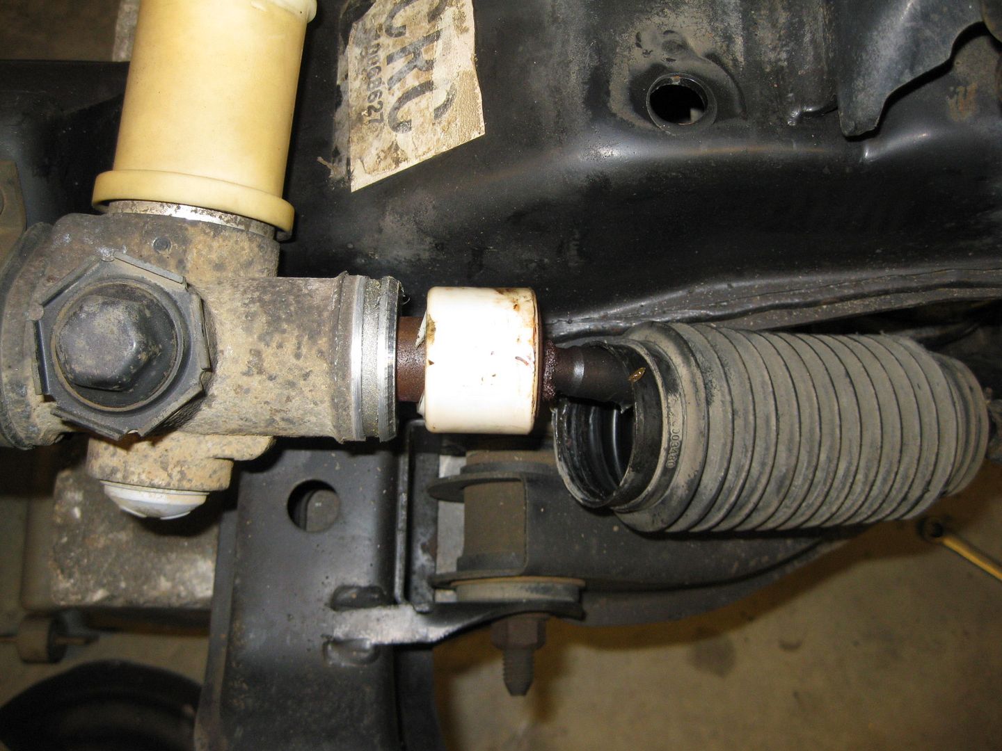
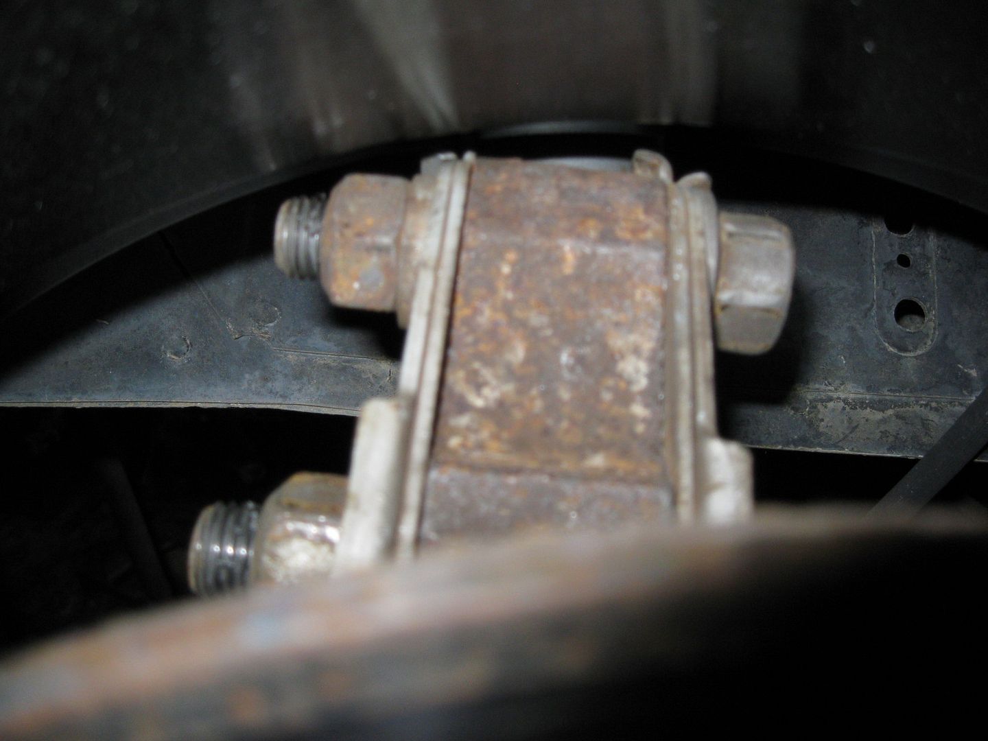
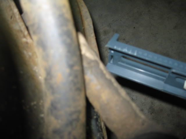
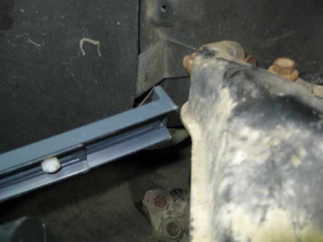
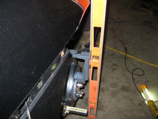
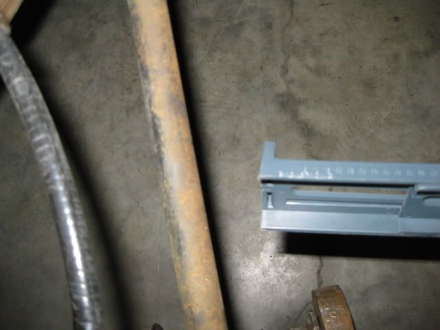
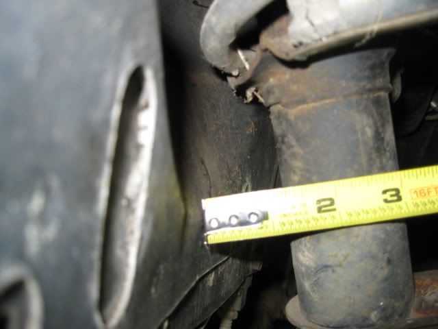
The front was pretty much as expected, but I noticed that full lock to the driver side was only 1 1/4 turns vs. 1 2/3 turn that the passenger side had. The culprit was a poor installation of Rodneys rack bushing. Here is how it was installed:
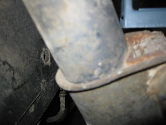
I drilled out the 2 rivets and was able to pull it in further and restore the rack to 1 2/3 turns to the driver side:
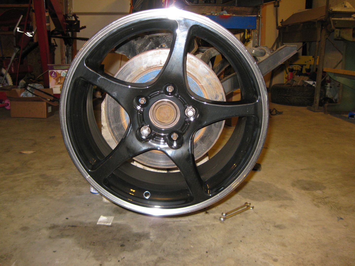
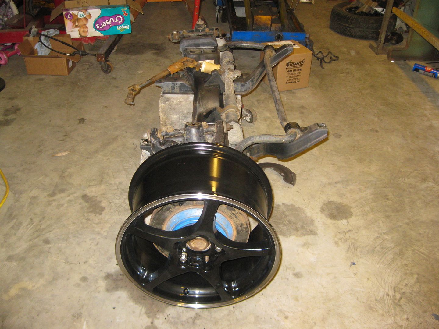
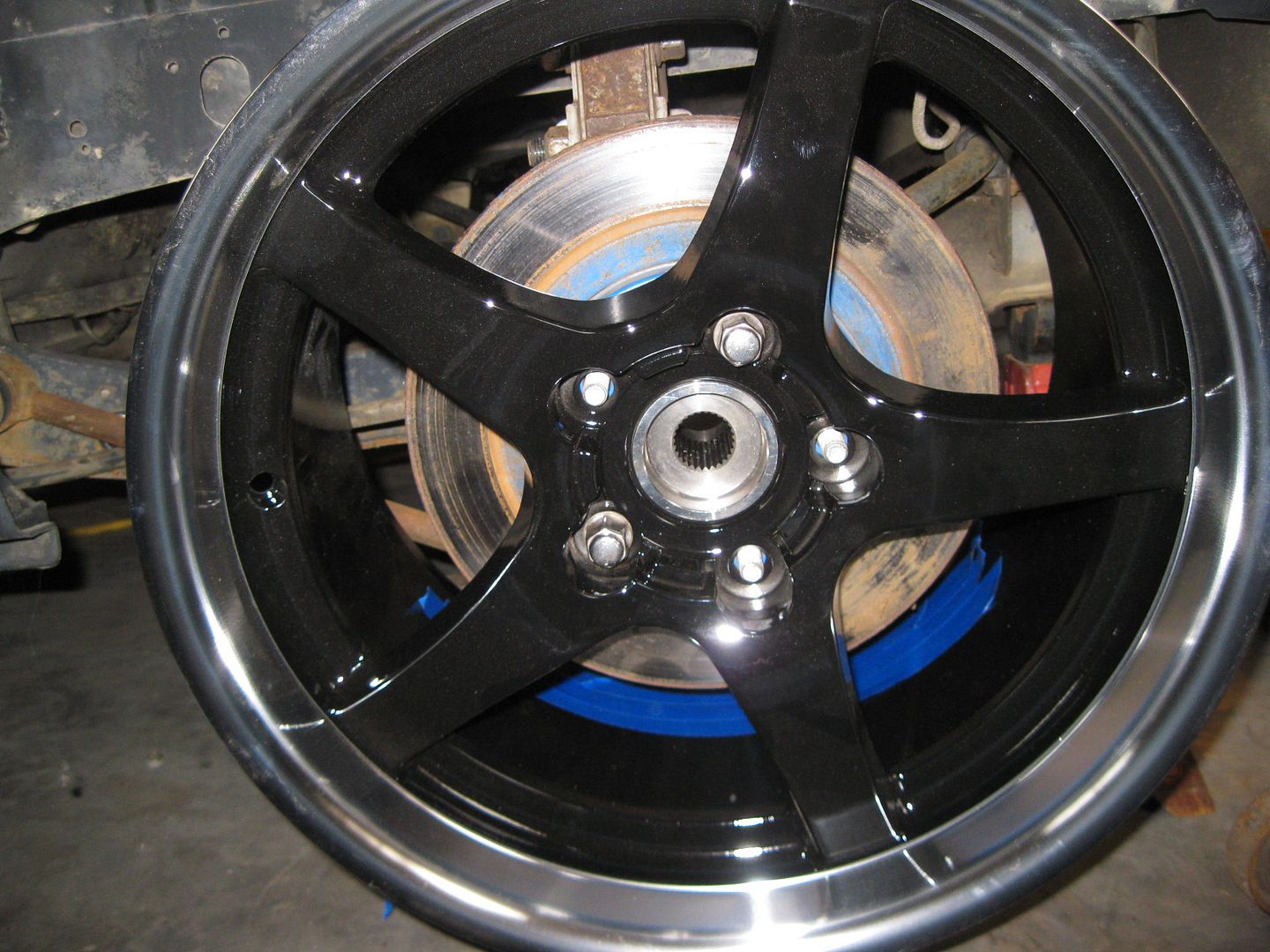
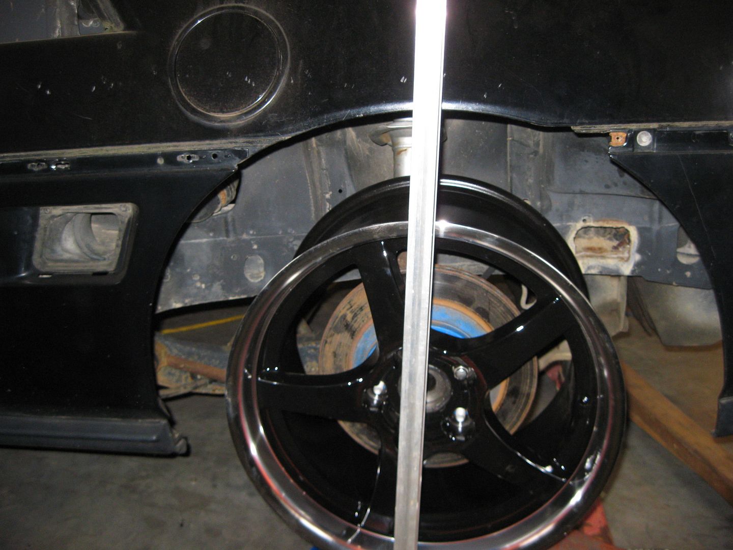
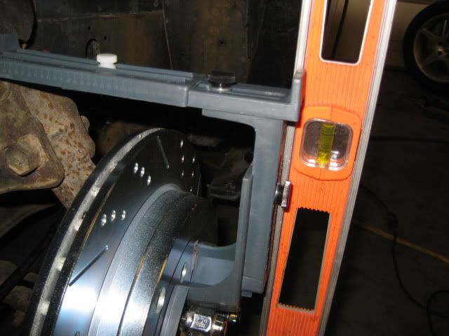
Then I started testing the wheel fitment (excuse the 12" C4 rotor, I havent drilled a set of my 13" rotors for this project yet):
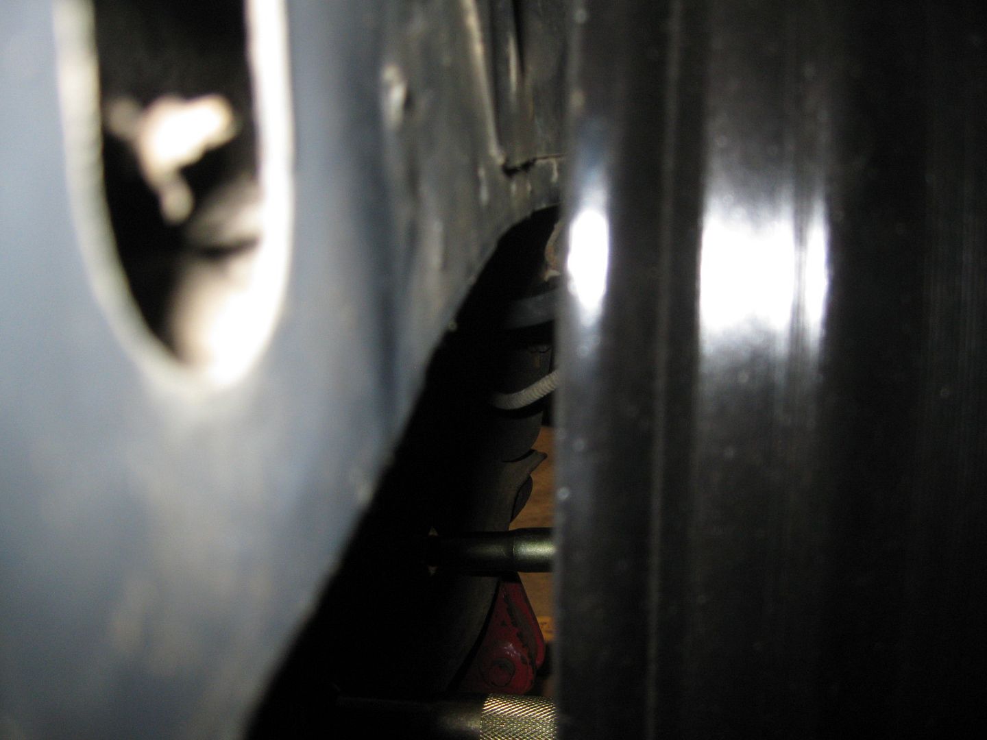
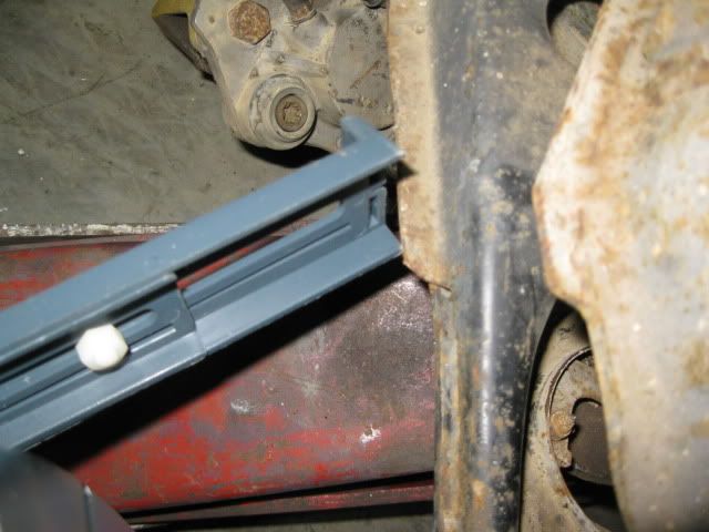
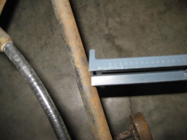
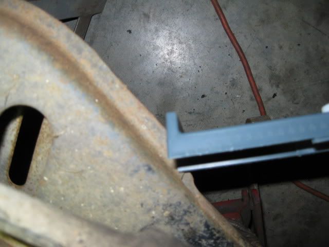
The interference with the lower a-arm is here:
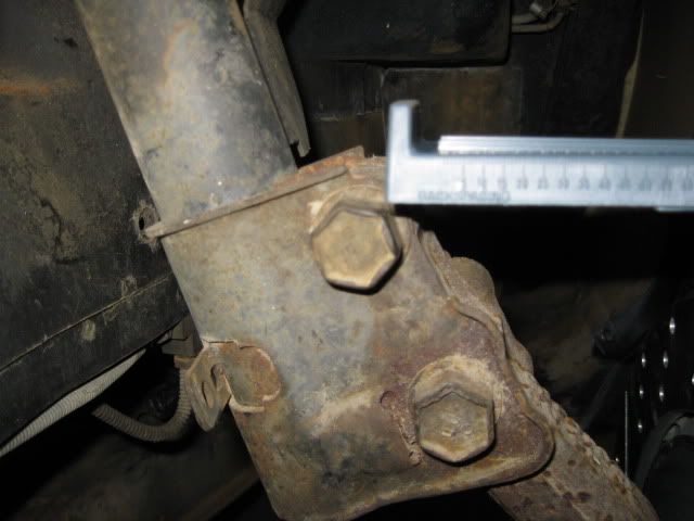
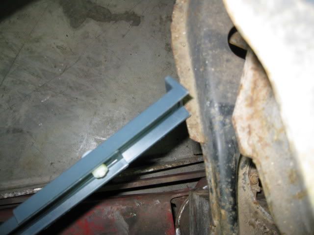
Still had a little more room to move on the rack:
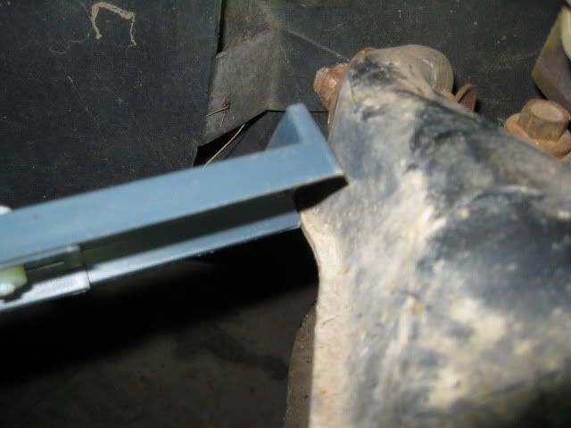
The interference with the upper a-arm happens when turning to the passenger side here:
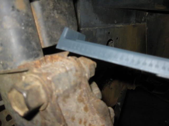
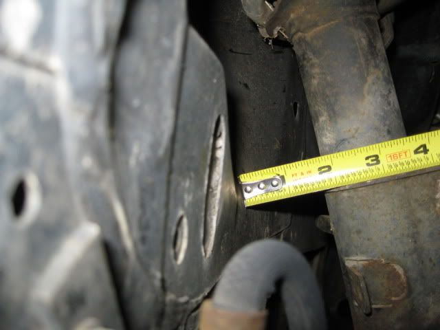
Here is how much travel is left on the rack:
Looks like I will need to do some minor clearance work while I rebuild this front end.
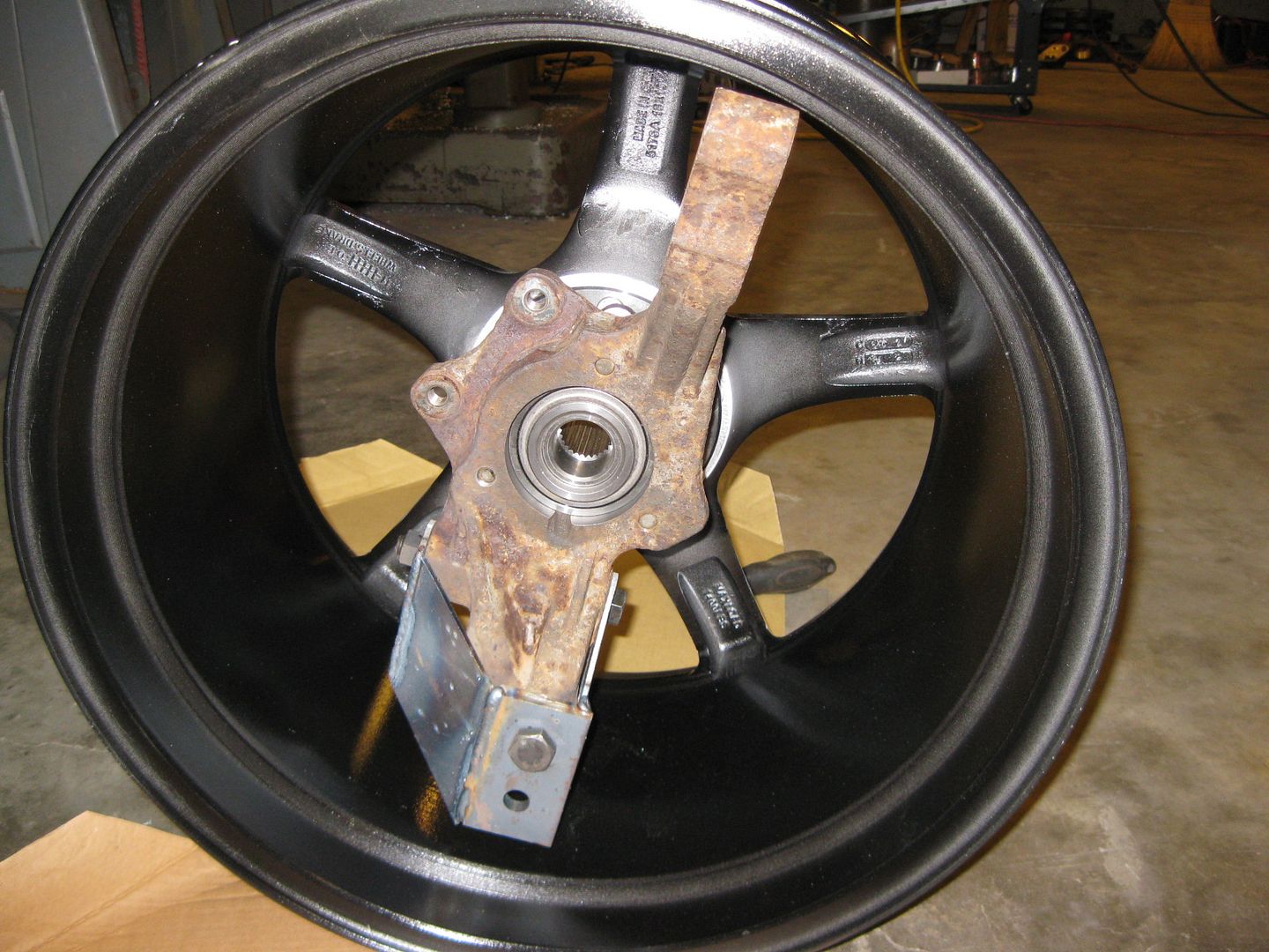
Then I moved on the rear... Wimpy 12" rotor:
Test fit of the upright with the lateral link relocation bracket:
On the car with stock lateral links:
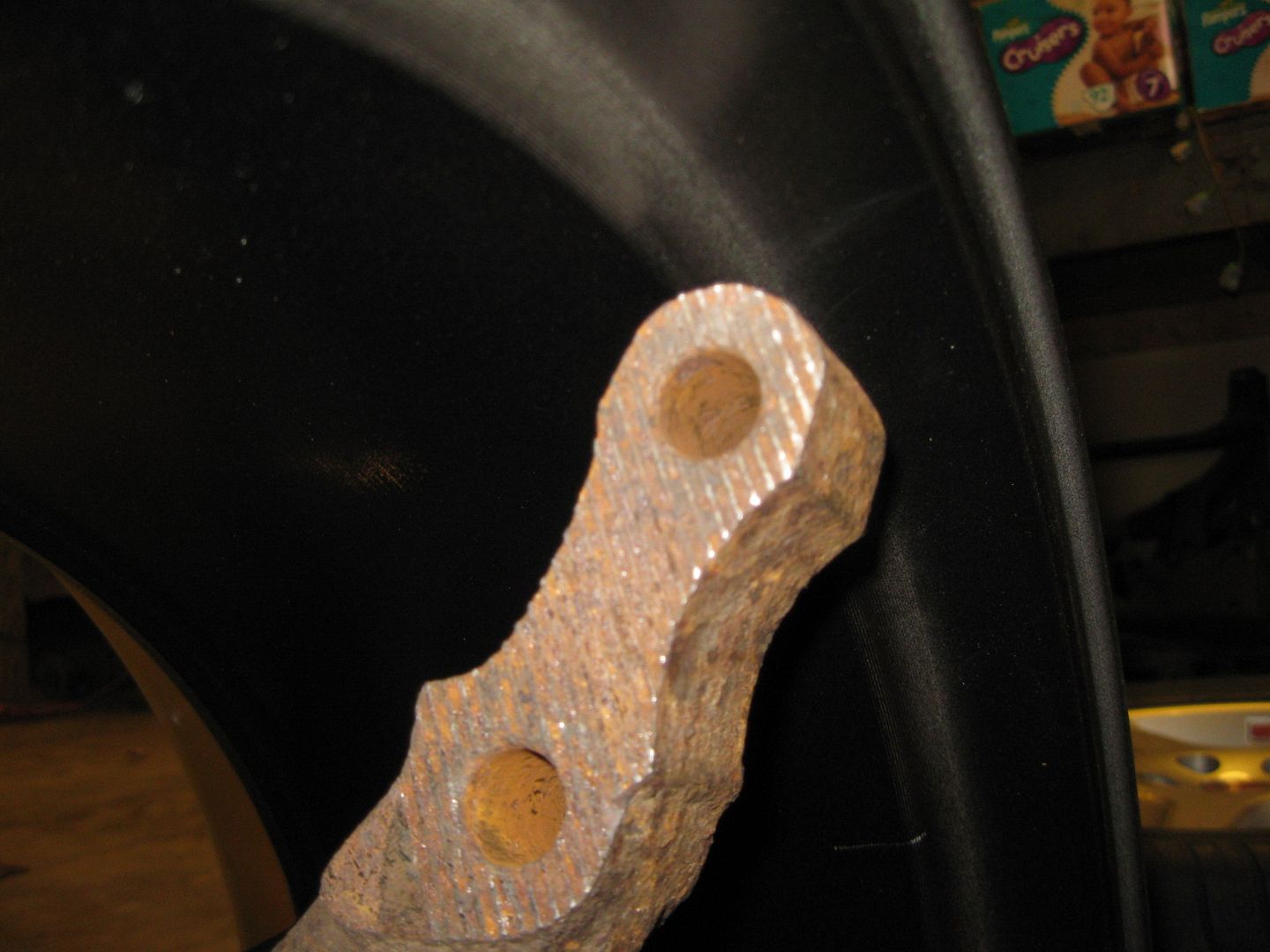
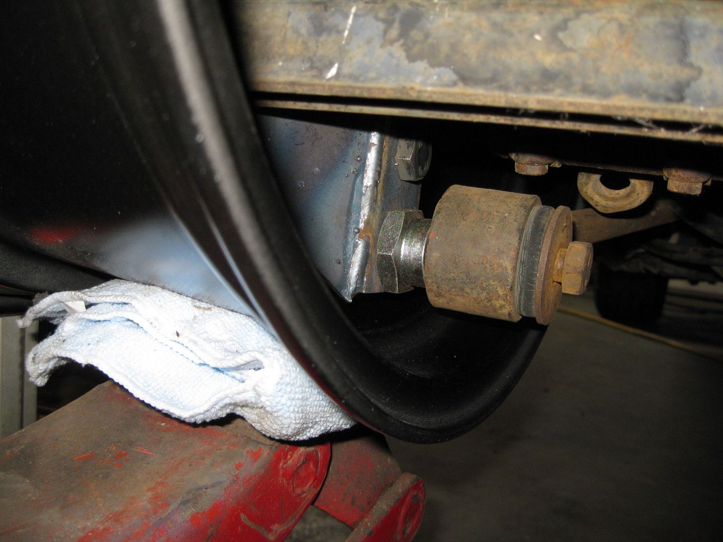
I did space out the trailing link mount about 1" to get the above clearance to the wheel:
Everything was looking good until this:
So out came the shorter adjustable lateral links (about 1 5/8" shorter). The strut doesn't have enough adjustment to get back to 0 camber, so I will probably need to relocated the top of the stut as well:
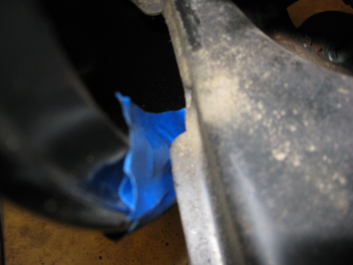
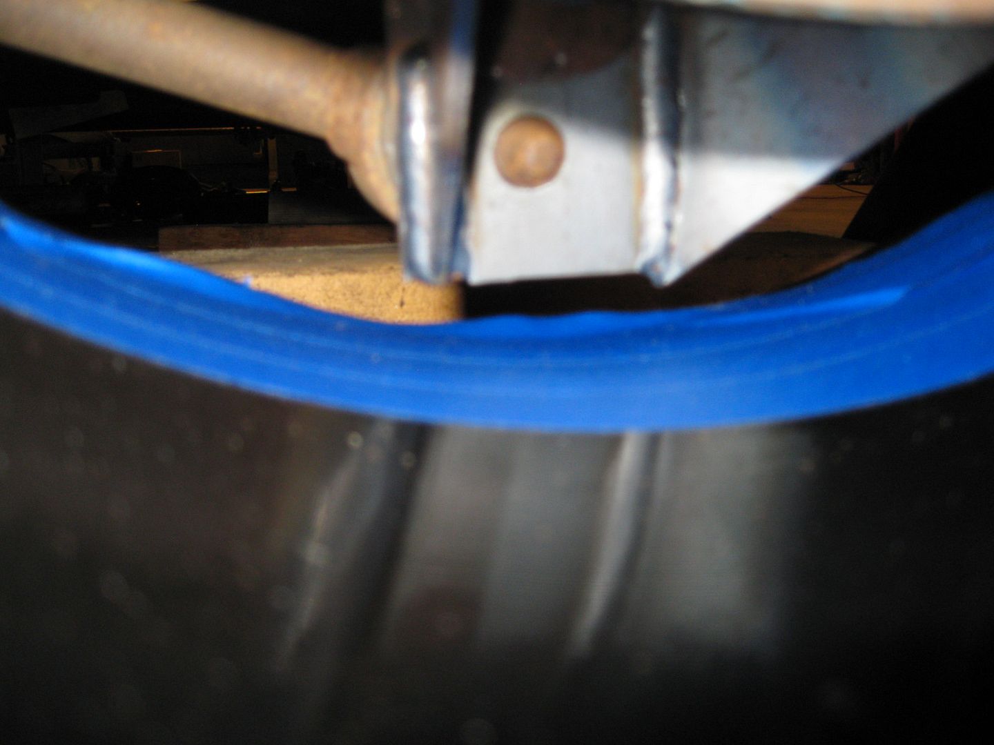
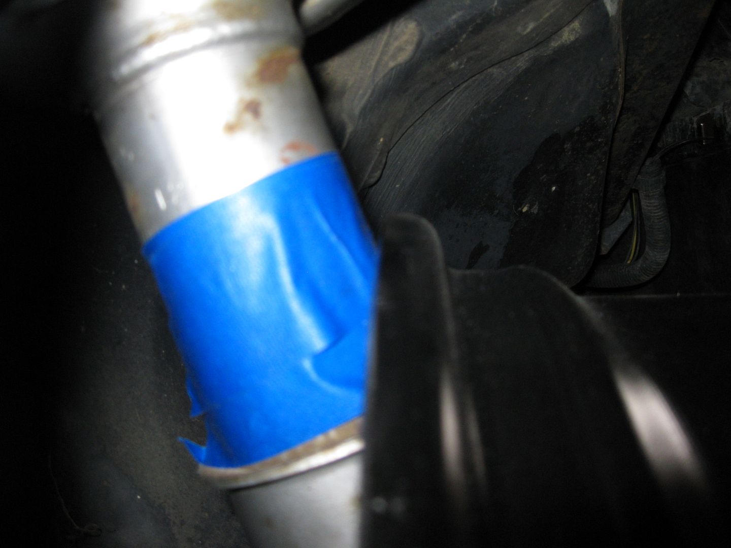
Wheel is getting close to the front frame rail:
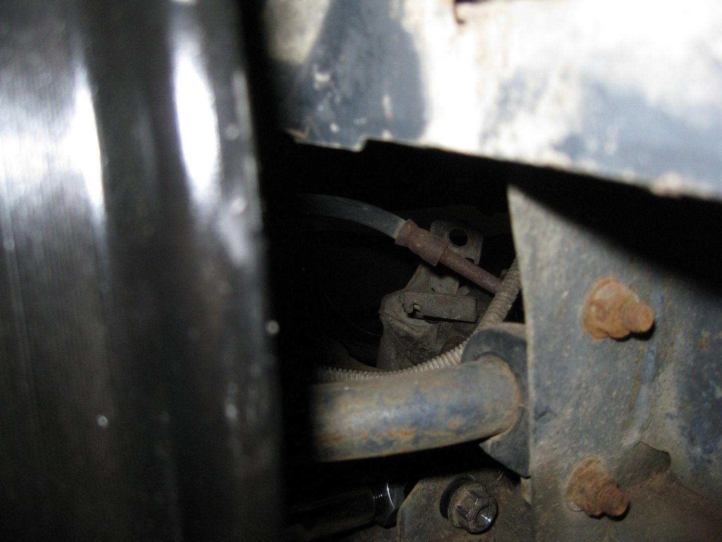
Wheel is also close to the rear frame (I will need to relocate the brake line bracket to clear the wheel):
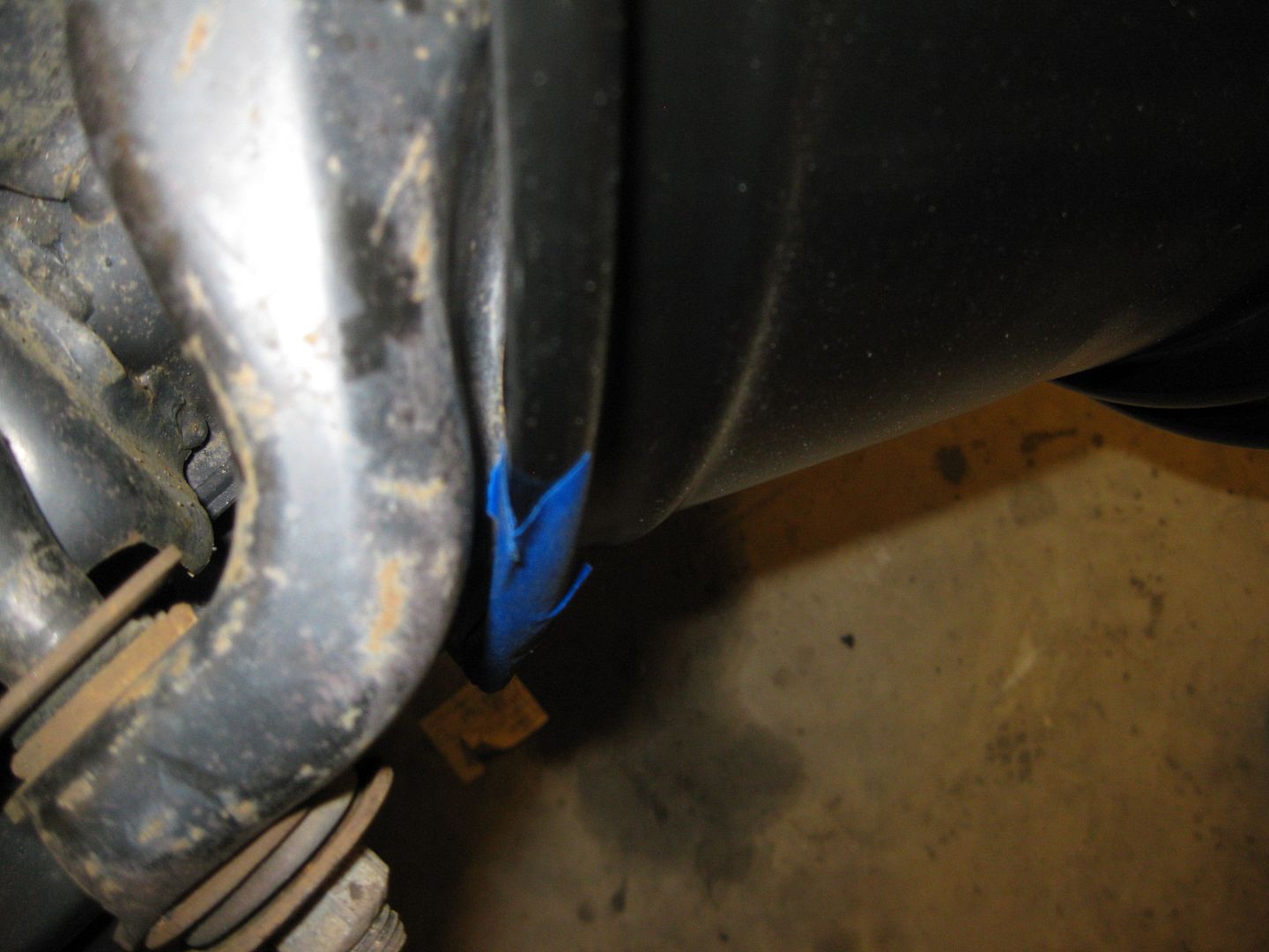
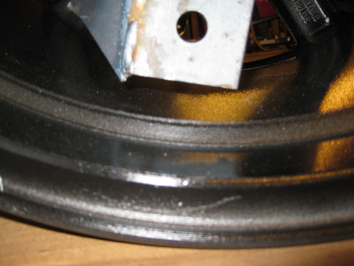
Wheel is very close to the strut (even after I added a .075" spacer - I took about .125 off the bearing... probably should not have):
But it does fit!
I removed the trailing link to get the wheel to fit so I will need to make a custom trailing link that will fit around the wheel. I will also need shorter axles, and need to relocated the top of the strut some as well. Here is a pick showing the available room with a coil over hat:
I'm paying attention to this! I'm with you...I don't want to put a wide body kit on my Formy either.
So, I have a set of Y2K C5 Rims on my Vette. 17" x 8.5" front. 18" x 9.5" rear. Do you think the 9.5" rear would have been a better setup?
I don't have coil overs in the rear of my Formula (yet) so I can't just take it off and throw it onto my Fiero for comparison, otherwise I would to help out. But to me, maybe the loss of the 1" might be worth it? Granted...I'm all for you trying to get a 10.5" wheel under there. Would look sick behind such a small car.
Also, would the WCF links help with this any? Since they look more adjustable then the stock links.
[This message has been edited by SOMFormula (edited 02-19-2012).]
The original designers put serrated teeth on that shaft where it contacts the cross member much like the bolted joint between the rear upright and strut. I don't understand the theory of designing a bolted joint in that manner considering that frictional force is independent of surface area.
That is a bit of an over-statement. Frictional force can be very much related to surface area, and surface condition, Since the coefficient of friction is only a number used to quantify the surface phenom. Considering contact mechanics is a very non-linear and complex series of differential equations.
I'm paying attention to this! I'm with you...I don't want to put a wide body kit on my Formy either.
So, I have a set of Y2K C5 Rims on my Vette. 17" x 8.5" front. 18" x 9.5" rear. Do you think the 9.5" rear would have been a better setup?
I don't have coil overs in the rear of my Formula (yet) so I can't just take it off and throw it onto my Fiero for comparison, otherwise I would to help out. But to me, maybe the loss of the 1" might be worth it? Granted...I'm all for you trying to get a 10.5" wheel under there. Would look sick behind such a small car.
Also, would the WCF links help with this any? Since they look more adjustable then the stock links.
The 18 x 9.5 stock wheels have a 65 offset, so instead of the wheels sticking out 1 5/8", they would only stick out about 7/8".
You can build your own rod end lateral links and same some $$$ - details in this thread. If you plan to pull in the wheels 7/8", then you should get all the swaged tubes 1" shorter than specified in the thread: https://www.fiero.nl/forum/Forum2/HTML/120882.html
I linked over to your thread about the links...fanTASTIC write up! Thank you for that. I'll have to go that route! That setup is HALF the price of the WCF links.
On my 88 i have 18 by 8.5 on the rear with 265, 35 rubber and 18 by 7.5 on the front with 225 45 i looked at all this so many times to try to get a 9 inch wide wheel in the rear and unless the offset is bringing the wheel out side the fender it is very difficut with out coilovers, I guess for thoes who are doing a wide body it will be OK but look kind of funny on stock body,
On my 88 i have 18 by 8.5 on the rear with 265, 35 rubber and 18 by 7.5 on the front with 225 45 i looked at all this so many times to try to get a 9 inch wide wheel in the rear and unless the offset is bringing the wheel out side the fender it is very difficut with out coilovers, I guess for thoes who are doing a wide body it will be OK but look kind of funny on stock body,
I wanted way more tire than 265 and willing to do the needed mods to get there (coil overs, shorter lateral links, new trailing link, relocated strut top). Above there is a pic of a 10.5 wheel already tucked under the stock body.
That is a bit of an over-statement. Frictional force can be very much related to surface area, and surface condition, Since the coefficient of friction is only a number used to quantify the surface phenom. Considering contact mechanics is a very non-linear and complex series of differential equations.
Perhaps it is an overstatement in this particular case and that's what I don't understand about these kind on bolted joints. Amontons Second Law is what I was referring to which is an approximation but applies quite well to non deformation conditions. The fact of the matter however is that reduced surface area (serrations) on that shaft causes deformation to the cross member which causes multiple problems. If the joint slips it wrecks one of the abutment surfaces making it harder to prevent from slipping a second time. If it doesn't slip and you need to adjust the camber it can become nearly impossible as the serrations tend to want to find their home in the existing deformations.
From what I recall contact mechanics is limited in it's application to static conditions. I'd be interested in a little education as to how it applies here but possibly in a different thread or via PM as I'd hate to sidetrack Guru's thread any more than I already have.
The serrations reduce the contact area to the point that the preload provide by the bolts creates enough contact pressure to cause the surface to yield and undergo plastic deformation.
Standard analysis of bolted joints *ONLY* applies to elastic deformation.


_Front_Wheels_vs_Stock1.JPG)
_Front_Wheels_vs_Stock_Top1.JPG)