I think the proper approach is to do what was suggested in the other thread.
Determine the desired track, ride height and tire size and that will determine the general location of the lower control arm mounting points. This assumes you want a level lower control arm at the desired ride height (which may not be the case). From there you set the desired camber and that will give you an arc for the possible upper control arm mounting points. Then use a suspension geometry program to determine the best location on that arc. You also need to consider anti-squat and bump steer.
Mounting point measurements from the original car are only relevant if the track remains the same. They can also be used as a starting point and as a sanity check.
Where could I get a program like that? Free? Online? The track is set in stone because I am using the stock Solstice sway bars and steering rack. I could then "tune" them if needed by trying diferent sizes. Ride height is also set, lower A arms will be level and in the same basic location as the stock Fiero pinnings.
Where could I get a program like that? Free? Online? The track is set in stone because I am using the stock Solstice sway bars and steering rack. I could then "tune" them if needed by trying diferent sizes. Ride height is also set, lower A arms will be level and in the same basic location as the stock Fiero pinnings.
My understanding of some of the limitations of the stock Fiero front suspension has to do with rack placement (Ackerman) and camber/caster curve. As far as I can figure out, you can have static negative camber or positive caster, but not both.
"I agree with Greg that the key issue is a rack ahead of wheel center promotes deflection understeer and rack behind wheel center will tend to have deflection oversteer. I would add that a rack behind wheel center does have two advantages 1)often allows a tighter vehicle turn radius by allowing higher maximum steer angles. 2) Allows you to design in the proper Ackermann correction without moving the rack much out of line with the outer tie-rods. If the rack is significantly forward or back of the outer tie-rod joint, steering forces will introduce an undesireable fore-aft force into rack."
Is there an engineering or design reason that drives you to those choices?
Yes, I dont realy have plans to change the stock geomitry of the KAPPA. So I would just put it all in as close to stock as I can. The ride height of the KAPPA is fine, no need to change. The steering rack determans the track, keeping it all original. The bearing cariers are MUCH taller than the Fiero allowing for a lower ride height and larger wheels.
Yes, I dont realy have plans to change the stock geomitry of the KAPPA. So I would just put it all in as close to stock as I can. The ride height of the KAPPA is fine, no need to change. The steering rack determans the track, keeping it all original. The bearing cariers are MUCH taller than the Fiero allowing for a lower ride height and larger wheels.
A point I tried to make above is that the Kappa geometry as implemented in the Kappa is probably not right for the Fiero due to the difference in engine placement and accompanying difference in centroid axis inclination.
quote
Originally posted by Will:
The Solstice suspension was designed for the Solstice, with packaging considerations totally different from those of the Fiero. Also, the Solstice is a front engine car, so roll axis inclination, etc. are not likely to be right for a mid/rear car.
[This message has been edited by Will (edited 09-01-2011).]
For an 88, I do think you are right. Other Fieros would most likely be better off with this suspension than a Chevette Citation combo. What we dont know is how negativly or posativly a KAPPA suspension will affect the 88? Then figure in the negative affects of compromized geomitry from lowering and wheel size and offsets. What is wores for the 88, stock KAPPA suspension wheels and ride height or compromized 88 suspension? We could make it even more compicated if we try to figure in engine, trans, and body swaps.
Maybe I am not like most on this forum? I would do this swap just to say I have it. Thats it. It looks SSSOOO much better than the stock Fiero stuff and the elimination of shock towers is super trick.
[This message has been edited by Rickady88GT (edited 09-01-2011).]
What we don't know is how negatively or positively a KAPPA suspension will affect the 88? Then figure in the negative affects of compromized geometry from lowering and wheel size and offsets. What is worse for the 88, stock KAPPA suspension wheels and ride height or compromized 88 suspension?
One of the main reasons I'm drawing out the stock '88 Fiero suspension, is so that these questions may be easier to answer, at least theoretically. The effect of things like lowered ride height and tires on a stock Fiero suspension should be easily analyzed once the main drawings are done. It would be considerably more work though to compare the impact of the Kappa suspension installation since a whole-scale effort to draw out its geometry would be needed. Without going through that effort, I think it would be difficult to know in advance if the net result would be positive or negative, so I can understand why you might be tempted to just go ahead an do it. It's a lot of work and time to analyze suspension geometry.
Here in the Canadian Maritimes, we don't have the luxury of just swapping in something else. We will soon only be able to install OEM approved modifications (fat chance of that with a Fiero!), or failing that, have to prove to a provincially certified mechanical engineer that suspension changes result in equal or improved handling over an OEM design. Without this special one-time approval, the normal garages that perform yearly mandatory mechanical fitness inspections won't even touch your car. (Hence the real reason I'm going through this exercise of drawing out the suspension.)
For an 88, I do think you are right. Other Fieros would most likely be better off with this suspension than a Chevette Citation combo. What we dont know is how negativly or posativly a KAPPA suspension will affect the 88? Then figure in the negative affects of compromized geomitry from lowering and wheel size and offsets. What is wores for the 88, stock KAPPA suspension wheels and ride height or compromized 88 suspension? We could make it even more compicated if we try to figure in engine, trans, and body swaps.
Maybe I am not like most on this forum? I would do this swap just to say I have it. Thats it. It looks SSSOOO much better than the stock Fiero stuff and the elimination of shock towers is super trick.
IOW, there are no design or engineering choices driving you to install the suspension exactly as it is in the Kappa.
In terms of camber performance, the early Fiero rear suspension is "good enough". IE, I can achieve enough static camber that the tire wears evenly when I explore the car's cornering limits. The early rear's deficiencies lie in bump steer and pro-squat. With lower control arms level, the early rear's roll center is likely too low.
The Kappa rear end may have camber performance that allows the Fiero to use less static camber to achieve the same dynamic camber. When installed with the lower control arms level, the Kappa setup will likely have a low rear roll center. This will NOT be superior to the stock Fiero hardware. I don't know how much anti-squat the Kappa platform has built-in, but it's probably NOT pro-squat like the Fiero, so that would be an improvement.
HOWEVER... If you change the elevation of the inner pivots of upper and lower control arms relative to the Kappa mounting, you can raise the rear roll center relative to what it would be in the Kappa and make it more appropriate to the Fiero. You can also configure the side view of the control arm pivots for anti-squat. This would involve raising the forward pivot of the LCA and lowering the rear pivot of the UCA. This is likely to run into problems with clearance to the transmission on the left side and the crank pulley on the right side. However, if you swap the control arms left for right, you can avoid that. Keep the knuckles on their original sides. The LCA would be "staggered" to the rear and the UCA to the front, opposite of the configuration in the Kappa. This would give you more flexibility in mounting the LCA pivots and setting up the suspension correctly for the Fiero.
I dont think the upper and lower arm are level. They do have anti-sqat built into the system. I just dont know how much. Not only that but I also think that the left and right A arm mounts upper and lower are closer at the front than the rear mounts, measured from side to side. BUT I could be wrong?
LOL, I know how that sounds, but it is an option. Just as the front "cradle" or K mmber drops out of the Fiero I would graft in or weld in that same KAPPA structure. Sounds crazy, but I have seen a sell booklet that show cased some after market suspension stuff for the KAPPA and they had a front clip/frame section from a Solstice to display the entire suspension system just like the Fiero system once removed. The plan would be to permenently weld it in place of the Fiero K member. The rear is a little more work. The KAPPA's are in the wecking yards ready for me to walk up with a Honda i2000 and a sawzal
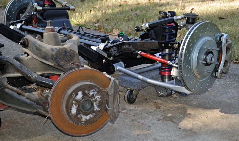
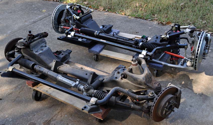
Rick could you post more side-by-side pictures? Also the rear suspension side by side?
While a stock Solstice suspension may or may not work, at least we're discussing it. That's a step in the right direction. There is obviously not just one solution to the suspension problem. Let's see which versions we can come up with.
Now we could do a solidworks/pro-engineer mockup of a solstice suspension and see how it reacts. Then add the data we know about the Fiero (CG, weight distribution, etc.)
btw.: Thanks to Borders going out of business :sheds tear: books on chassis engineering and Solidworks and other software can be had for cheap. (not to say that there isn't a learning curve, but no time to start like the present. Dassault Systems (the guys behind Solidworks) Parametric Technology (Creo, which is the new name for Pro/Engineer also do student versions of the software, which are much nearer affordable. Another solution is looking up a near college that has an engineering program. Who knows, maybe there is a student in search of a semester project. Another avenue are regional distributors of 3D design/CAD software: They often hold free seminars, Q and A sessions, etc. where they try to peddle their products.
[This message has been edited by Austrian Import (edited 09-02-2011).]
LOL, I know how that sounds, but it is an option. Just as the front "cradle" or K mmber drops out of the Fiero I would graft in or weld in that same KAPPA structure.
The "Clip" is the front frame and body forward of the firewall. It is *NOT* the same as the suspension crossmember.
[This message has been edited by Will (edited 09-02-2011).]
The "Clip" is the front frame and body forward of the firewall. It is *NOT* the same as the suspension crossmember.
I understand. In short I would think about cutting out the suspension pinnings from the KAPPA and weld them into the Fiero. This would also make a more presice frame/suspension system. The stock Fiero only has one pin to locate the front K member. This pin does not lokate the K member all that close to ideal. The +/- is to much. Welding in a suspension mount system will help.
On the early cars, the crossmember is effectively located by the rear LCA pivots which are welded to the body.
The '88's different, but with 8 mounting bolts instead of 4, the hole tolerances in random directions are likely to locate the subframe pretty precisely.
And on the '88's the relative relationships or the pivots are all determined by the subframe anyway, so if the subframe's out a tiny bit relative to the chassis, it doesn't matter. The toe adjustment makes up for it.
[This message has been edited by Will (edited 09-03-2011).]
Now we could do a solidworks/pro-engineer mockup of a solstice suspension and see how it reacts. Then add the data we know about the Fiero (CG, weight distribution, etc.)
Another solution is looking up a near college that has an engineering program. Who knows, maybe there is a student in search of a semester project. Another avenue are regional distributors of 3D design/CAD software: They often hold free seminars, Q and A sessions, etc. where they try to peddle their products.
Austrian, I thought you were doing the CAD design??? I am a mechanical designer for a major teir one supplier to the automotive industry. On my work PC I have UG NX4, UG NX7.5, Catia V5 R16, R18, R19, ProE WF4, and SolidWorks 2010. I am proficient in these softwares and use them every day.
But I am not going to volunteer to do this. I highly doubt anyone could provide the data needed to create such a model with any accuracy. Every pivot point of the suspension is an axis, which in order to model correctly, has to have accurate X, Y, Z coordinates. To model up something like this with very simple solids would take a lot of manhours. If you wanted it to look like some of the videos you've posted; where the suspension components have near production geometry, that would require a LOT of manhours at the tube. Then to create a motion simulation, forget it. This would not be a short project, and would require someone with a fair amount of CAD proficiency.
[This message has been edited by lateFormula (edited 09-03-2011).]
Where could I get a program like that? Free? Online? The track is set in stone because I am using the stock Solstice sway bars and steering rack. I could then "tune" them if needed by trying diferent sizes. Ride height is also set, lower A arms will be level and in the same basic location as the stock Fiero pinnings.
When I was actively racing my Fiero in the 90's I use A-ARM Suspension Geometry PRO from Autoware. It was very easy to enter in the 3D coordinates of all the pivot points and it spit out all the curves. It was crude and only did one end of the car but it was cheap and simple to use. It was great for doing what-if changes and looking at the results.
I would be surprised if there isn't much better open source software available today.
Totally off topic, but here is the story, of which the suspension design chapter was taken.
"Larry Ellison, CEO of Oracle, commissioned Kirkham Motorsports build the ultimate, cost is no object, roadster. Spanning the 2 1/2 years between idea and completion, this book reveals the secrets of the ultimate car."
Lotus Suspension Analyzer is a pretty decent software for analyzing the kinematics. If you scour the internet you might be able to find a copy. I was only able to use the shark module so I could only play around with the kinematics. If you can get the the raven module working you can specify bushing and tire stiffness and it will do a compliant analysis and can simulate performance characteristics of particular maneuvers.
Austrian, I thought you were doing the CAD design??? I am a mechanical designer for a major teir one supplier to the automotive industry. On my work PC I have UG NX4, UG NX7.5, Catia V5 R16, R18, R19, ProE WF4, and SolidWorks 2010. I am proficient in these softwares and use them every day.
But I am not going to volunteer to do this. I highly doubt anyone could provide the data needed to create such a model with any accuracy. Every pivot point of the suspension is an axis, which in order to model correctly, has to have accurate X, Y, Z coordinates. To model up something like this with very simple solids would take a lot of manhours. If you wanted it to look like some of the videos you've posted; where the suspension components have near production geometry, that would require a LOT of manhours at the tube. Then to create a motion simulation, forget it. This would not be a short project, and would require someone with a fair amount of CAD proficiency.
I never considered it to be a short project. I'm not that naiive. It's part of the reason why I wanted this to be a collaborative open source project. (I've worked a bunch of projects where people donated their time towards a common good. How do you think other big projects get done i.e.: Firefox anyone? ) So it's not just one person investing a lot of manhours into this. A lot of the structural measurements are already in this thread, the rest can be taken from a Factory service manual, and/or a bodyshop manual.
Lotus Suspension Analyzer is a pretty decent software for analyzing the kinematics. If you scour the internet you might be able to find a copy. I was only able to use the shark module so I could only play around with the kinematics. If you can get the the raven module working you can specify bushing and tire stiffness and it will do a compliant analysis and can simulate performance characteristics of particular maneuvers.
Originally posted by Austrian Import: A lot of the structural measurements are already in this thread, the rest can be taken from a Factory service manual, and/or a bodyshop manual.
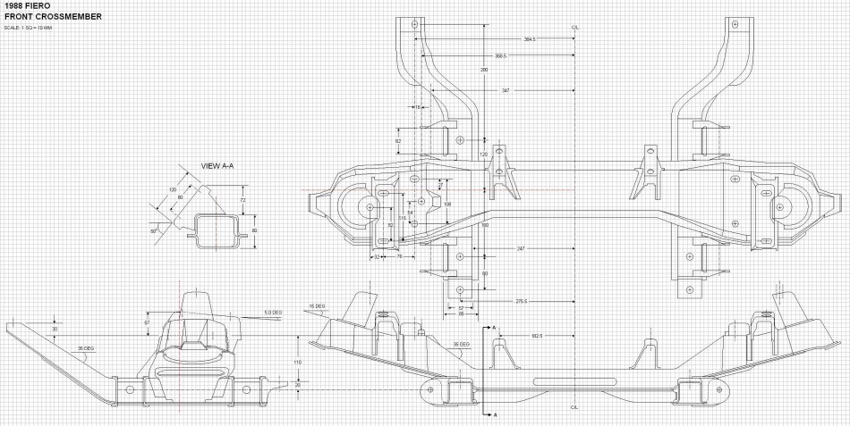
Not so. Only the structural measurements for the rear end can be found in this thread so far. I can guarantee you that the rest (ie the front end dimensions) can't be found in the service manual or bodyshop manuals. They only give the measurements for where the front cross member attaches to the rest of the frame, nothing about the cross member, the control arms, knuckles or steering rack though.
Within two or three days I'll have completed the three-view of the bare front cross member though, and will post it here. The rest of the pieces will follow in the coming weeks... it takes time. That'll be my contribution.
The SCCA autocross rules for the Prepared Class lists the Fiero with an alternate rear suspension-- double A-arm. Apparently at some time someone was modifying the cars enough it made it into the rules as an allowable suspension modification.
This is an exception to the rule that generally requires cars to retain the "original basic type of rear suspension" from the manufacturer.
I suppose I should chime in here since I’m working on the same thing in my back burner mode (since I’m working on many projects at once). But here’s where I’m at working on my 88: - Fundamentally, I feel if you are going to the trouble to change the suspension geometry you might as well change the bearing too as they are outdated as well. - At first I was going to keep the rear knuckle and just change the bearing out for something that can handle a few races before it self destructs. The variety of 5-100 rims available with acceptable offsets and rim widths is rather poor, so I decided to go with something that has basically what I need and readily available…Corvette C5 (not Z06 – rims wider than needed). Long story short, S10 4x4 front bearing pulled apart, hub pressed onto a common bearing for Ford, Mazda and Jaguar. Knuckle re-machined to accept said bearing. Make a retaining cup. Change to coil-overs. Rear end done! Right? Nope, like we know from this thread and others, the rear end still does not gain enough negative camber. But for those that don’t care about that it’s a nice upgrade for the rear. - Note: above is what I have done so far, below is what I’m now working on - My current thought to gain more negative camber on the rear while being abele to have close to zero static camber is to pocket the frame rail and add mounting points for an upper A arm inside that pocket. Make an adapter for the strut mount that allows pivot. - This is about as far as I’m willing to go with the re-design of the rear end. Once I have something in CAD I’ll make a decision whether it’s worth the change or not. - For the front, I have Corvette C5 front knuckles that will be installed stock with custom A arms, and adapters to go from vette(or whatever) to Fiero(or whatever). To keep service costs down, ball joints will not be Vette and the bearing will have an alternative but retain the wheel with stock spacing. My cost on a C5 front bearing is $330 Canadian. I’m not sure it’s worth it. It’s not the cost so much, I just don’t trust that it’s really that much better. I’d rather tell GM to shove it and find something else that will work. Sorry about the little rant but Corporations piss me off.
For those that are going to ask me a bunch of questions, please be advised. I’m not putting a lot daily hours into this, I don’t come here often and I post very rarely. I will be reading from time to time as I’m interested and can contribute.
Let me also say that I have not included many details as it would take a lot of time to convey and would add little to the design phase (from my standpoint). For example: When I say things like "pocket the frame rail", it should be assumed that the frame rail will be reinforced to allow for the new loading. Until such time that I have a working CAD model and can asses for stresses and shock loading, add reinforcement until I have at least a 2.5 safety factor and determine if it's reasonable to add such reinforcement, or if an alternative solution should be examined.
- My current thought to gain more negative camber on the rear while being abele to have close to zero static camber is to pocket the frame rail and add mounting points for an upper A arm inside that pocket. Make an adapter for the strut mount that allows pivot. .
This is exactly what I have in mind for the solo project - assuming I ever get back on it (depends on finances & if I find a good engine cheap - looking for a 3.4 short block). But do you really need to pocket the frame rails? I was thinking that with a pretty stiff suspension you could just add mounts to the outside of the frame rails. I'll admit I have not done any measuring in this regard.... but with little travel & a static of near zero neg camber you could achieve the right neg camber for the little body roll you'd have. ~ Paul aka "Tha Driver"
I would not feel safe machining out the rear knuckles for a larger bearing. They are VERY THIN to start with. This is, if you implied that?
I did. The Fiero knuckle has a 71.1mm ID and the replacement bearing has an 80mm OD. I need a lip to catch the bearing on the back of the knuckle so it doesn't slide out the inside. The knuckles are grey cast not aluminum. "very thin" mans what anyway? What thickness do I require to maintain a reasonable safety factor?
If the knuckle fails I can use a smaller bearing or make a billet knuckle, or weld up a steel one.
Originally posted by Tha Driver: But do you really need to pocket the frame rails? I was thinking that with a pretty stiff suspension you could just add mounts to the outside of the frame rails. I'll admit I have not done any measuring in this regard.... but with little travel & a static of near zero neg camber you could achieve the right neg camber for the little body roll you'd have. ~ Paul
You kind of answered your own question. How much travel do you want? Once I have a CAD model it will answer the question better. Your mounting distance and angle will be dependent on your spring rate. You basically have to work it backwards because every time you change your spring rate or your ride height you will need to modify your mounting position on the inside.
Everything has to be worked backwards to what most people are thinking. It goes more like this: 1) How many lateral G's do I reasonably want to make. 2) How much do I want to spend on tires? 3) Assuming that you have worked out a ratio between 1 and 2, you can now determine the width of tire you need to maintain your required patch of tire to road contact based on the weight of the individual loads 3b) Is the tire I calculated available? If no then go back to 1 and start over with a fresh frame of mind. 4) Will my existing suspension geometry and characteristics allow me to maintain that contact patch? 5) If no to 4, then we find ourselves here at this thread. And things get rather complicated because there are an infinite number of ways to achieve the desired results which will very from person to person, and car to car. 6) How much suspension travel do you want? (assuming the minimum that will suit your needs) Every different length of travel requires a different length of upper arm or mounting point. (for me it's 3" (for now) in compression to the stop). Also note: this answer along with your suspension geometry will set your spring rate. 7) What ride height are you targeting? (assuming the minimum that will suit your needs) Every different height requires a different mounting point. (for me it's 5") 8) Set a target time and budget to obtain your results. Please note that within this constraint you may not achieve 4) even after modification 9) Here's where all hell brakes loose because there are too many different paths to continue a list. Honestly I should have stopped after number 1)
Finally a bit of progress to report. Here's the three-view drawing of the '88 front cross member. By itself, the cross member drawing is rather useless so I won't post any higher resolution pictures of the drawings here, suffice to say that progress is being made though. One notable exception is that the upper front control arm mount is angled 5 degrees. If you want a better view of the dimensions you can pull up individual views in my build thread here: www.fiero.nl/forum/Forum3/HTML/000116-11.html . Next up, the control arms.


 books on chassis engineering and Solidworks and other software can be had for cheap. (not to say that there isn't a learning curve, but no time to start like the present.